background image

38 – 

English

Repair Instructions

A

B

C

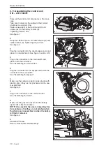
9.17 Assembling the chain brake

1

Lubricate as instructed in "Service Data".

2

Place the spring and shaft (B) with the heel in its 

groove on the crankcase followed by the catch (C).

See figure 1.

3

Compress the large spring (A) and place it in its 

groove.

See figure 2.

4

Refit the cover and screws (3x).

Tightening torque 1 Nm.

See figure 3.

5

Plug in the connectors, replace the cables and 

fasten the connector for the chain brake sensor to 

its attachment.

6

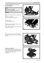
Fit the motor 

See "Assembling the motor"

7

Assemble the saw.

Refer to "Basic dismantle/assembly"

WARNING!
Exercise care to ensure the springs 
do not fly out and causes personal 
injury. Wear protective goggles!

Fig 3

Fig 1

Fig 2

Содержание T536 Li XP

Страница 1: ...Workshop Manual English T536 Li XP ...

Страница 2: ......

Страница 3: ...nt and therefore reserves the right to modify the design and appearance of products without prior notice Table of contents Index 4 Introduction and safety regulations 6 Technical data 10 Service tools 11 Service data 12 Diagnosis and troubleshooting 14 Basic dismantle assembly 16 Safety equipment 18 Repair instructions 22 ...

Страница 4: ...d guard 19 I Impeller Assembling the impeller 25 Cleaning and inspection 25 Dismantling the impeller 25 Introduction and safety instructions Changes 7 General 7 General Instructions 8 Numbering 7 Security 7 Special Instructions 8 Structure 7 Symbols in the Workshop Manual 9 Symbols on the saw 9 Target group 7 Tools 7 K Keypad Replacing the keypad 30 M Main switch Assembling the piston main switch ...

Страница 5: ......

Страница 6: ... and safety regulations Table of contents 2 1 General 7 2 2 Safety 7 2 3 Target group 7 2 4 Changes 7 2 5 Tools 7 2 6 Structure 7 2 7 Numbering 7 2 8 General instructions 8 2 9 Special instructions 8 2 10 Symbols on the saw 9 2 11 Symbols in the Workshop Manual 9 ...

Страница 7: ...l become out of date In order to prevent this the Manual should be read together with all service information concerning the chain saw in question 2 5 Tools Special tools are required for some stages All service tools are listed in the Workshop Manual Usage is made apparent in each section Always use original Husqvarna Spare parts Service tools Accessories 2 6 Structure This Workshop Manual can be...

Страница 8: ...o the blood circulation which means mortal danger Use hearing protection when test running The bar chain and drive wheel cover chain brake must be fitted before the saw is started otherwise the clutch can work itself loose and cause personal injury Insufficient chain lubrication can result in chain breakage which can cause serious or even fatal injury Check that the brake is applied when removing ...

Страница 9: ...the chain saw Filling with chain oil Indication of chain direction Chain brake Starting Stopping savE Battery saver mode Warning lamp Fault indicator 2 11 Symbols in the Workshop Manual This symbol warns of personal injury when the instructions are not followed Use protective gloves Use protective goggles ...

Страница 10: ...h mm inches 9 52 3 8 Drive link mm inches 1 1 0 043 Chain speed at saveE m s 15 Automatic oil pump Yes Chain speed at normal operation m s 20 Volume oil tank Liters US pint 0 20 0 42 Usable cutting length cm inch 23 33 9 13 Weight without battery oil bar and chain kg lbs 2 4 5 3 kg L OIL ...

Страница 11: ...uch as run times temperature number of starts and speed It is also possible to enter service notes linked to the product ID These records can then be read for example at the next service There is also a troubleshooting guide in the form of a diagnostic tool and a list of saved error codes The software in battery powered products can also be updated with the Common Service Tool COMMON SERVICE TOOL ...

Страница 12: ...y The numbers by bolted components represent the tightening torque in Nm Lubricate chain saw oil Lubricate with grease x4 3 5 Nm 4 mm x2 1 Nm x2 1 Nm x2 1 Nm 1 Nm x2 1 2 Nm 1 2 Nm x2 1 Nm x2 1 Nm x4 3 5 Nm 4 mm S N 20150100001 S N 20150100001 ...

Страница 13: ...English 13 Service data 2 5 3 Nm 4 mm 4 mm x9 1 7 2 Nm 4 mm x2 2 5 3 Nm 2 5 3 5 Nm T27 1 2 Nm 4 mm x3 1 Nm ...

Страница 14: ...4 English 6 Diagnosis and troubleshooting Diagnosis and troubleshooting Table of contents 6 1 Remove the battery 15 6 2 Connect the diagnostic tool 15 6 3 No signal to diagnostic tool 15 6 4 Overhaul 15 ...

Страница 15: ...diagnostic tool for trouble shooting the battery NOTE Refer to the manual for the Diagnostic Tool Battery for detailed instructionsl See figure 2 2 Diagnose troubleshoot according to the diagnostic tool instructions and make any necessary repairs as instructed in the relevant chapter in this manual 6 3 No signal to diagnostic tool 1 Check that the contact on the battery and the bat tery contact on...

Страница 16: ...16 English 7 Basic dismantle assembly Basic dismantle assembly Table of contents 7 1 Battery 17 7 2 Drive wheel cover and bar 17 7 3 Front hand guard 17 7 4 Separate the saw 17 ...

Страница 17: ...See figure 1 Replace the battery once assembly has been completed 7 2 Drive wheel cover and bar Release the brake by moving the hand guard back wards Remove the bar nut and the drive wheel cover saw chain and bar See figure 2 Assemble in the reverse order 7 3 Front hand guard Refer to dismantling front hand guard in the Safety equipment chapter 7 4 Separate the saw Remove the screws 9x and lift of...

Страница 18: ...the hand guard 19 8 2 Assembling the hand guard 20 8 3 Dismantling the throttle lockout throttle and spring 20 8 4 Assembling the throttle lockout throttle and spring 21 8 5 Replacing the chain catcher 21 8 6 Replacing the spike bumper 21 8 7 Replacing the belt hook and rope eye 21 ...

Страница 19: ...drive wheel cover saw chain and bar Refer to Basic dismantle assembly 3 Release the brake by moving the hand guard back wards Note It is essential this procedure is carried out as it facilitates the assembly of the hand guard Loosen screws A and B for the hand guard See figure 1 4 Turn the hand guard horizontal so screw hole B on the left hand side passes its fastening on the saw See figure 2 5 Co...

Страница 20: ...protective goggles 1 Make sure the brake pin is in the correct position See Figure 5a 2 Place and tension the spring as shown in Figure 5b 3 Secure the saw with assembly fixture 502 51 02 01 Align the hand guard heels as shown in Figure 5c At the same time pull the hand guard over on the opposite side See Figure 5d B A A B Fig 5c Fig 5b Fig 5a Fig 5d ...

Страница 21: ...astening in the throttle See figure 7 Cleaning and inspection Clean and check all parts thoroughly Parts must be replaced if cracked or showing signs of other defects Always use original spare parts Check that the recoil spring is intact and retains all its tension See figure 8 Fig 7 Fig 8 Safety equipment 4 The hand guard is correctly fitted when the spring comes into the slot on the hand guard a...

Страница 22: ...ith a new one 1 Dismantle the drive wheel cover saw chain and bar Refer to Basic dismantle assembly 2 Remove the screw and replace the chain catcher Tightening torque 2 5 3 Nm See figure 10 8 6 Replacing the spike bumper Always replace a worn spike bumper with a new one 1 Dismantle the drive wheel cover saw chain and bar Refer to Basic dismantle assembly 2 Remove the screws 2x and replace the spik...

Страница 23: ... N 2015100001 30 9 11 Assembling the control unit S N 2015100001 31 9 12 Dismantling the control unit S N 2015100001 32 9 13 Assembling the control unit S N 2015100001 33 9 14 Replacing the keypad 34 9 15 Replacing the keypad and wiring 35 9 16 Dismantling the chain brake 36 9 17 Assembling the chain brake 37 9 18 Dismantling the chain brake sensor 38 9 19 Assembling the chain brake sensor 38 9 20...

Страница 24: ...embly 2 Remove the screws 4x See figure 1 3 Press in catch A and unplug the connector B Insert a screwdriver C above the connector D and carefully press down to release and unplug the connector Remove the motor NOTE Connector B must not be forced Use a screwdriver to carefully unplug the connector See figure 2 Fig 2 Fig 3 Fig 4 Cleaning and inspection Clean and check the motor The motor must alway...

Страница 25: ... the clutch drive shaft See figure 1 Motor with temperature sensor and Gen 2 control unit Note If you have a chain saw with a motor that has the extra wiring for the temperature sensor insert the loose connector in the holder No connection is needed See figure 2 Motor without temperature sensor and Gen 1 control unit No connection is needed See figure 3 2 Rotate the motor shaft back and forth unti...

Страница 26: ... the motor See figure 1 9 5 Assembling the impeller 1 Press the impeller onto the motor Make sure the motor shaft A protrudes 1 85 mm See figure 1 2 Assemble the chain saw Refer to Basic dismantle assembly Fig 1 Fig 2 Fig 1 Cleaning and inspection Clean and check the impeller The impeller must always be replaced with a new one if cracked or showing signs of other defects Always use original spare ...

Страница 27: ...nd bar Separate the crankcase Refer to Basic dismantle assembly 2 Unplug the connector from the keypad carefully loosen the connector from the self adhesive tape and put the connector and cable to one side See figure 1 3 Remove the trigger switch and unplug connector A Take loose the connector B using a small screw driver to carefully free the heels D on each end of the connector and main switch f...

Страница 28: ... the sensor in the crankcase 2 Apply grease 588 17 64 01 inside the connector before assembly See A figure 2 Connect the cables See figure 3 Apply grease on both sides of the connector as shown in figure 2 B 3 Make sure the cables are held in place inside with plastic clips so they are not pinched when the saw is assembled See figure 4 4 Assemble the chain saw Refer to Basic dismantle assembly A B...

Страница 29: ... move the connector and cable to the side See figure 1 3 Remove the trigger switch Detach connector B using a small screwdriver to carefully free the heels C on each end of the con nector and tigger switch NOTE Do not pull the wires See figure 2 Cleaning and inspection Clean and check the trigger switch The trigger switch must always be replaced with a new one if cracked or showing signs of other ...

Страница 30: ...e pins before assembly See figure 1 2 Connect the wires to the trigger switch 3 Place two dots of grease as close as possible to the connector on the yellow wires See figure 2 4 Place the trigger switch in the crankcase See figure 3 5 Attach the keypad connector to the trigger switch See figure 4 6 Assemble the chain saw Refer to Basic dismantle assembly Fig 1 Fig 2 Fig 4 Fig 3 ...

Страница 31: ...assembly 2 Dismantle the motor See Dismantling the motor 3 Disconnect the contact from the keypad See Dismantling the keypad 4 Remove the main switch and unplug the connectors See Dismantling the main switch 5 Unplug the connector for the chain brake sensor A See figure 1 6 Remove cable retainer B and unscrew cable re tainer C See figur e 2 7 Remove the screws E and D Remove the control unit and b...

Страница 32: ... section 9 10 4 Plug in the connectors to the main switch and place it into the crankcase See Assembling the main switch 5 Plug the connector into the keypad and fasten the connector to the main switch See Assembling the keypad 6 Make sure the cables are held in place inside with plastic clips so they are not pinched when the saw is assembled See figure 3 7 Plug in the connectors to the motor and ...

Страница 33: ...before dismantling Make sure to position them correctly to avoid pinching when the chain saw is reas sembled 1 Dismantle the drive wheel cover saw chain and bar Separate the crankcase Refer to Basic dismantle assembly 2 Remove the motor See Dismantling the motor 3 Remove the screws holding the control unit and battery terminal See figure 1 4 Detach the wire bracket from the contol unit in the orde...

Страница 34: ... the cable stays as far to the left as possible to avoid pinching See figure 3 Repair Instructions 9 13 Assembling the control unit S N 2015100001 1 2 Fig 4 B A Fig 2 Fig 1 Fig 3 4 Make sure the gray area A around the battery ejector B is free from cables NOTE It is essential the area is completely free from cables so that they are not pinched when the chain saw is assembled or when the battery is...

Страница 35: ...e 2 4 Make sure the temperature is at least 15 C and the surface where the keypad is mounted differs no more than 3 C from the ambient temperature See figure 3 5 Remove the protective tape from the new keypad and press it onto the surface Press on the panel with 10 N cm for at least 10 seconds NOTE Do not bend the keypad when assem bling See figure 4 6 Apply grease inside the connetor See figure 5...

Страница 36: ...igger switch Refer to Dismantling the trigger switch 1 2 Fig 2 7 Connect the wiring to the control unit and make sure the sealing and bracket is attached properly See figure 2 for the correct order of attachment 8 Place the stripe in the brake lever bracket B as shown in figure 3 9 Place the wiring as shown in figure 3 Observe the position of the tape C 10 Connect the brake lever connector D See f...

Страница 37: ... lift out the cover See figure 1 5 Catch the large spring A with a screwdriver and remove it See figure 2 6 Lift out the spring and shaft B followed by the catch C See figure 3 Cleaning and inspection Clean and inspect all parts of the chain brake Components must always be replaced with new ones if cracked or showing signs of other defects Always use original spare parts See figure 4 WARNING Exerc...

Страница 38: ...ing A and place it in its groove See figure 2 4 Refit the cover and screws 3x Tightening torque 1 Nm See figure 3 5 Plug in the connectors replace the cables and fasten the connector for the chain brake sensor to its attachment 6 Fit the motor See Assembling the motor 7 Assemble the saw Refer to Basic dismantle assembly WARNING Exercise care to ensure the springs do not fly out and causes personal...

Страница 39: ...d bar Separate the crankcase Refer to Basic dismantle assembly 2 Unplug the connector A See figure 1 3 Dismantle the chain brake See Dismantling the chain brake 4 Remove the sensor See figure 2 9 19 Assembling the chain brake sensor 1 Place the sensor in the crankcase See figure 1 2 Assemble the chain brake See Assembling the chain brake 3 Plug in connector A and place it in its attachment on the ...

Страница 40: ... chain brake 6 Empty the chain oil tank 7 Remove the screws 2x and lift straight out the cover lubricating shaft and cylinder See figure 1 8 Lift out the lubricating shaft and cylinder and re move them from the rubber hose See figure 2 9 Poke loose the rubber hose from outside and insert it through the hole while removing it See figure 3 Cleaning and inspection Clean and inspect all parts of the o...

Страница 41: ...the cylinder and lubricating shaft into the hole in the hose and press the components into the crankcase See figure 2 5 Attach the oil pump with the screws 2x Tightening torque 1 Nm 6 Assemble the chain brake See Assembling the chain brake 7 Assemble the control unit See Assembling the control unit 8 Fit the motor See Assembling the motor 9 Assemble the saw Refer to Basic dismantle assembly 10 Fil...

Страница 42: ...htening torque 1 2 Nm See figure 1 2 Assemble the drive wheel cover saw chain and bar Refer to Basic dismantle assembly Fig 1 Fig 1 Fig 2 Cleaning and inspection Clean and inspect all parts of the chain tensioner Components must always be replaced with new ones if cracked or showing signs of other defects Always use original spare parts See figure 2 9 24 Replacing the chip guard Always replace a w...

Страница 43: ...es loose from the crankcase as well 4 Remove the bar bolt and its reinforcement from the chain oil tank 5 Place the bar bolt reinforcement A onto the bar bolt B insert them into the oil tank with round nose pliers and through the hole in the crankcase See figure 1 6 Pull out the bar bolt with a nut Insert a spacer between the nut and the crankcase See figure 2 NOTE Make sure the bar bolt reinforce...

Страница 44: ...e chain oil cap If the chain oil cap is damaged it can be opened using the tool spanner Place the spanner in the groove in the cap and turn anti clockwise Always replace a damaged cap with a new one Always use original spare parts See figure 1 Fig 1 ...

Страница 45: ...1 Make sure the trigger switch signal connector is properly as sembled dry not damaged and free from corrosion See pic 3 in appendix Motor connector not correctly assem bled 2 Make sure the motor connector s are correctly assem bled See pic 4 in appendix Internal damage to trigger switch 3 Replace trigger switch Short circuit in control unit 4 Replace control unit Electric motor jerks shortly when...

Страница 46: ...nal connector reassemble See pic 3 in appendix Short circuit in keypad 3 Replace keypad Short circuit in trigger switch 4 Replace trigger switch Warning triangle on keypad blinks shortly after activation where after the product hangs up with the green led on Bad communication signal between battery and product 1 Make sure power connectors between battery and product are not damaged and free from d...

Страница 47: ... signal connector is properly as sembled not damaged and free from corrosion See picture 3 in appendix Motor connector not correctly assem bled 2 Make sure the motor connector s are correctly assem bled See pic 5 in appendix Internal damage to trigger switch 3 Replace trigger switch Short circuit in control unit 4 Replace control unit Electric motor jerks shortly when applying the trigger then sto...

Страница 48: ...d 3 Replace keypad Short circuit in trigger switch 4 Replace trigger switch Warning triangle on keypad blinks shortly after activation where after the product hangs up with the green led on Bad communication signal between battery and product 1 Make sure power connectors between battery and product are not damaged and free from dirt See pic 1 in appendix 2 Make sure the small cables bet ween power...

Страница 49: ... the fan and the green LED co mes on for 3sec If not replace charger Flashing red warning triangle on char ger when battery is inserted Bad connection between char ger and battery 1 Make sure power connectors between charger and battery are not damaged and free from dirt See pic 1 in appendix Over temperature on battery 2 Leave battery in the charger to cool off 1 5minutes Too low ambient temperat...

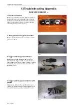
Страница 50: ...ery and charger Only colors may vary 2 Keypad connector Make sure the two connector parts are fully at tached Look for broken or loose cables 3 Trigger switch signal connector Make sure the white female connector is fully attached to the trigger switch Look for broken or loose cables Also look for signs of water corrosion or shortcirquit on connector and pins when disas sembled 12 Troubleshooting ...

Страница 51: ... the motor connector are assembled with a tight fit Pic 4 and that the connecting pins are not damaged 5 Communication cables Make sure the three small communication cables are not loose or damaged Troubleshooting Appendix Pic 6 Pic 5 Pic 4 ...

Страница 52: ...n keypad connector Make sure the that there are no broken or dama ged wires Pic 2 3 Trigger switch signal connector Make sure the white female connector is fully attached to the trigger switch Look for broken or loose cables Also look for signs of water corrosion or shortcirquit on connector and pins when disas sembled Pic 3 Pic 1 Pic 4 Pic 3 Pic 2 4 Trigger switch signal connector with grease App...

Страница 53: ...ector Make sure the motor connector are assembled with a tight fit Pic 8 and that the connecting pins Pic 9 are not damaged 5 Communication cables Make sure the three small communication cables are not loose or damaged Pic 6 7 Pic 6 Pic 5 Pic 7 Pic 8 ...

Страница 54: ...54 English Troubleshooting Appendix 7 26 pin wiring cable chain saw Make sure the 26 pin wiring cable is properly as sembled dry and not damaged Pic 10 Pic 9 Pic 10 ...

Страница 55: ......

Страница 56: ... 115 53 98 26 2015W36 ...

Отзывы: