
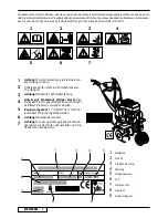

ENGLISH -
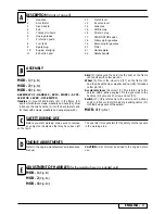
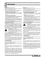
OPERATION
MOD.2
(Fig.F
VI
-F
VII-
F
VIII
-F
IX
-F
X
)
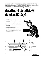
Once the machine has been set up properly, start the
engine as follows:
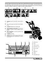
Before starting work, it is necessary to carry out the
following:
- set the trasport wheels (5) upwards.
a)
Engines with choke system:
if the model is equipped with an accelerator, when
the engine is cold, position the accelerator lever (2)
on START
Engines with primer system:
Press the fuel-enrichment pump located on the car-
burettor 3 or 4 times.if the model is equipped with an
accelerator, position the accelerator lever (2) on MAX.
b)
Grip the engine start grip (10) and pull the starter
rope gently until you feel the resistance caused by
compression. Release the handle; then give the starter
rope a sharp tug.
For further information and explanations, read careful-
ly the user instruction manual of the engine
WARNING! Never keep the two handles (12-13)
activated at the same time. It may cause damage
to the belts and pulleys
WHEN THE TILLER IS ON
:
in order to make the tiller
blades (6) run, handle (12) must be depressed. When
working with the tiller, keep the handle depressed.
If the handle is released, the tiller blades will come to
a stop.
Depress the skid in order to work in depth and decrease
the pressure to move forwards.
REVERSE-GEAR
:
for engaging the reverse-gear, only
handle (13) must be actuated.
How to stop the engine:
for this purpose, shift the accele
-
rated lever into STOP position.
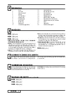
The four cutter stars (6) can be pulled off, and the combina
-
tion of cutters allows working widths from 5 to 55 cms.
For assembly, introduce the blade star (6) to the rotary
shaft (N) and make the two holes (P) match: then introduce
pin (R) by fastening it with the respective spring. Make sure
that the hoeing blades are assembled in the right direction,
i.e. the cutting angle showing forward.
MOD.1
(Fig.F
I
-F
II-
F
III
-F
IV
-F
V
)
Once the machine has been set up properly, start the
engine as follows:
Before starting work, it is necessary to carry out the
following:
- set the trasport wheels (5) upwards.
a)
Engines with choke system:
if the model is equipped with an accelerator, when the
engine is cold, position the accelerator lever (2) on
START
Engines with primer system:
Press the fuel-enrichment pump located on the car-
burettor 3 or 4 times.if the model is equipped with an
accelerator, position the accelerator lever (2) on MAX.
b) Grip the engine start grip (10) and pull the starter
rope gently until you feel the resistance caused by
compression. Release the handle; then give the starter
rope a sharp tug.
For further information and explanations, read careful-
ly the user instruction manual of the engine.
Initially position the hook (15) of the forward drive cable
and the hook (16) of the reverse clutch cable in the holes
(II°) of the respective handles (1-13).
Should the handle action not follow the cutter clutch,
position the hook into hole (I°) of the handle, while on the
contrary insert it into hole (III°) should the cutters remain
engaged even on release of the handle itself.
WARNING!
Never keep the two handles (12-13)
activated at the same time. It may cause damage
to the belts and pulleys.
WHEN THE TILLER IS ON:
in order to make the tiller bla-
des (6) run, handle (12) must be depressed. When working
with the tiller, keep the handle depressed. If the handle is
released, the tiller blades will come to a stop.
Depress the skid in order to work in depth and decrease
the pressure to move forwards.
REVERSE-GEAR
: for engaging the reverse-gear, only
handle (13) must be actuated.
How to stop the engine: for this purpose, shift the accele
-
rated lever into STOP position.
The four cutter stars (6) can be pulled off, and the combina
-
tion of cutters allows working widths from 5 to 55 cms.
For assembly, introduce the blade star (6) to the rotary
shaft (N) and make the two holes (P) match: then introduce
pin (R) by fastening it with the respective spring. Make sure
that the hoeing blades are assembled in the right direction,
i.e. the cutting angle showing forward.
4
Содержание MEPPY
Страница 87: ...ELLHNIKA 1 2 3 4 5 6 7 1 1 2 3 4 5 6 7 1 2 3 4 5 6 7 8 9 ...
Страница 88: ...ELLHNIKA g H apovstash asfaleiva dosmevnh apo to cerouvli prevpei 2 ...
Страница 89: ...ELLHNIKA n MOD 1 Fig EI MOD 2 Fig EII MOD 4 Fig EIII 3 ...
Страница 90: ...ELLHNIKA 4 ...
Страница 91: ...ELLHNIKA 5 ...
Страница 92: ...ELLHNIKA 6 ...
Страница 93: ...ELLHNIKA 7 TεΧvikóζ ΔΙευθυvTήζ Husqvarna Outdoor Products Italia spa Via Como 72 23868 Valmadrera LC ...
Страница 144: ...144 12 13 ...
Страница 145: ...145 30 2 1 25 24 4 26 17 21 23 31 28 29 27 5 4T 15 10 HONDA GCV135 20 ...
Страница 146: ...146 ...
Страница 147: ...147 ...
Страница 148: ...148 12 15 I II III 13 16 I II III 12 13 13 12 35 25 55 P P N R 6 5 2 10 MOD 1 ...
Страница 149: ...149 12 13 12 13 35 25 55 P P N R 6 2 10 5 5 MOD 2 ...
Страница 150: ...150 38 22 12 12 22 2 39 4 10 35 55 12 6 35 36 37 5 32 4 33 34 6 MOD 3 17 10 START MAX 2 10 MIN 2T 4T ...
Страница 151: ...151 12 47 48 18 19 11 S T Q S 13 45 46 S S T Z 12 43 44 S T Q S Y 13 42 S S T Z 12 41 X ...
Страница 152: ...152 53 56 52 55 54 Q 53 56 5149 50 48 51 19 11 18 12 48 ...
Страница 154: ......
Страница 155: ......