


7
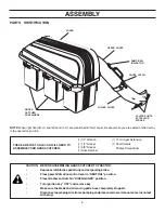
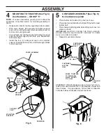
SUPPORT POST (See Fig. 4)
Use Hardware - - GROUP "B"
CAUTION: Container support is spring
loaded and locked to the cover. Handle
cover assembly carefully so as not to
unlatch the cover from the container
support.
•
Rotate cover assembly onto its side as shown.
•
Secure support tubes to cover assembly using short hex
bolts, long hex bolts, and locknuts as shown. Tighten
all hardware securely.
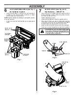
1
REAR MOUNTING BRACKET and
SUPPORT PLATE (See Figs. 1 & 2)
Use Hardware - - GROUP "A"
•
Install support plate to inside of drawbar as shown, using
two (2) 7/16-14 x 3/4 hex bolts and the two threaded
upper holes in the plate. Do not tighten at this time.
NOTE:
Be sure to align the four (4) lower threaded holes of
the support plate with the holes in the drawbar.
•
Assemble the mounting bracket as shown to the outside
of the drawbar using four (4) 7/16-14 x 3/4 hex bolts and
the four (4) lower threaded holes of the support plate.
Tighten all hardware securely.
Fig. 2
COVER SEAL (See Fig. 3)
No hardware required
•
Align mark on seal with mark at cover opening.
•
Work seal into opening so cover sits between flanges of
seal.
2
3
ALIGNMENT
MARKS
COVER SEAL
Fig. 3
DRAWBAR
HEX BOLTS
THREADED
UPPER HOLES
SUPPORT
PLATE
Fig. 1
HEX
BOLTS
SUPPORT
PLATE
DRAWBAR
THREADED
LOWER HOLES
MOUNTING
BRACKET
LOCKNUTS
LOCKNUTS
S U P P O R T
POSTS
LONG
HEX BOLTS
SHORT
HEX BOLTS
COVER
ASSEMBLY
Fig. 4
ASSEMBLY
Содержание CG46A
Страница 13: ...13 SERVICE NOTES ...


