


10
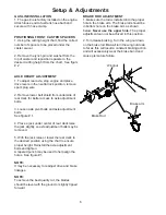
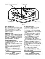
AUXILIARY BLADE DRIVE BELT
(48" MODELS ONLY)
To adjust tension of the auxiliary belt rotate nut
on linkage that is attached to deck strap located
on the right side of cutter deck. See Figure 6.
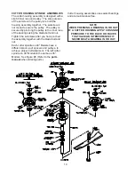
TRANSMISSION DRIVE BELT
To increase the tension of the transmission belt,
loosen the nut on the underside of the transmis-
sion idler pulley located under the rear deck,
slide the idler assembly inward to increase
tension and tighten the nut to secure. See
figures 4 & 5.
BELT GUIDES
Belt guides under rear deck are adjusted as
shown in figures 4 and 5
NOTE: The blades should come to a stop
from maximum speed within 7 seconds after
disengaging.
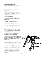
BLADE ENGAGEMENT LEVER
The blade engagement lever needs to be
adjusted so the lever does not come in contact
with control panel when the lever is in the off
position.
To adjust, remove the clevis pin from the yoke
and adjust by turning the yoke. The clevis pin
connects the blade engagement lever to the
yoke, and the yoke is connected to the blade
engagement rod that runs to the bellcrank on
the rear deck.
TRANSMISSION IDLER PULLEY
36" MODEL
48" MODEL
Figure 4
Figure 5
TRANSMISSION IDLER PULLEY
TRANSMISSION BELT
1/4" CLEARANCE
1/2"
ENGINE PULLEY
1/8" CLEARANCE
1/8" CLEARANCE
TRANSMISSION BELT
1/8" CLEARANCE
1/2"
ENGINE PULLEY
102036
103463
103462
102036
103462
103462
Содержание 968999117
Страница 17: ...17 Model Number Serial Number Date of Purchase Dealer Information Notes ...
Страница 18: ......


