background image

TROUBLESHOOTING CHART

26

1741506

Trouble

Cause

Correction

Difficulty starting

Defective spark plug.

Replace spark plug.

Water or dirt in fuel system.

Use carburetor bowl drain to flush and
refill with fresh fuel.

Engine runs erratic

Blocked fuel line, empty gas tank,
or stale gasoline/petrol.

Clean fuel line; check fuel supply; add
fresh fuel.

Engine stalls

Unit running on CHOKE.

Set choke lever to RUN position.

Engine runs erratic; loss of
power

Water or dirt in fuel system.

Use carburetor bowl drain to flush and
refill with fresh fuel.

Excessive vibration

Loose parts; damaged impeller.

Stop engine immediately and disconnect
spark plug wire. Tighten all bolts and
make all necessary repairs. If vibration
continues, have the unit serviced by a
competent repairman.

Unit fails to propel itself

Drive belt loose or damaged.

Replace drive belt.

Unit fails to discharge snow

Auger drive belt loose or damaged.

Adjust auger drive belt; replaced if dam-
aged.

Auger control cable not adjusted
correctly.

Adjust auger control cable.

Discharge chute clogged.

Stop engine immediately and disconnect
spark plug. Clean discharge chute and
inside of auger housing.

Foreign object lodged in auger.

Stop engine immediately and disconnect
spark plug wire. Remove object from
auger.

Содержание 5021 E

Страница 1: ...s important information on Safety Assembly Operation and Maintenance Product Imformation The owner must be certain that all the product information is included with the unit This information includes the INSTRUCTION BOOKS REPLACEMENT PARTS and WARRANTIES This information must be included to make sure state laws and other laws are followed 2007 07 ...

Страница 2: ...ssembled and are sold in cartons It is the responsibility of the owner to make sure the as sembly instructions in this manual are exactly followed Other units are purchased in an assembled condition On assembled units it is the responsibility of the owner to make sure the unit is correctly assembled The owner must carefully check the unit according to the instructions in this manual before it is f...

Страница 3: ...ment Hazard Symbols and the meanings These symbols are used on your equipment and defined in your operating manual Review and understand the meanings The use of one of these symbols combined with a signal word will alert you to potential hazards and how to avoid them Explosion Toxic fumes Shock Hot Surface Fire Operator s Manual Read and understand before performing any activity or running equipme...

Страница 4: ... nozzle in contact with the rim of the fuel tank or container opening at all times until refueling is com plete Do not use a nozzle lock open device g Replace gasoline cap securely and wipe up spilled fuel h If fuel is spilled on clothing change clothing immediate ly 5 Use extension cords and receptacles as specified by the manufacturer for all units with electric drive motors or electric starting...

Страница 5: ...t tool not your hands Service Maintenance And Storage 1 Check shear bolts and other bolts at frequent intervals for proper tightness to be sure the equipment is in safe work ing condition 2 Never store the machine with fuel in the tank inside a building where ignition sources are present such as hot water and space heaters or clothes dryers Allow the en gine to cool before storing in any enclosure...

Страница 6: ... 15 HOW TO MOVE FORWARD 15 BEFORE STARTING THE ENGINE 16 HOW TO STOP THE ENGINE 16 HOW TO START THE ENGINE 16 HOW TO START A COLD ENGINE 16 HOW TO START A WARM ENGINE 17 HOW TO START A WARM ENGINE WITH A FROZEN STARTER 17 HOW TO CLEAR A CLOGGED DISCHARGE CHUTE 17 SNOW THROWING TIPS 17 MAINTENANCE 19 EMISSIONS CONTROL 19 GENERAL RECOMMENDATIONS 19 ENGINE POWER RATING INFORMATION 19 AFTER EACH USE 2...

Страница 7: ...perating your unit All WARNING CAUTION and instructional mes sages on your unit should be carefully read and obeyed Personal bodily injury can result when these instructions are not followed The information is for your safety and it is important The safety decals below are on your unit If any of these decals are lost or damaged replace them at once See your local dealer for replacements These labe...

Страница 8: ... DASH PANEL Used on Model 6210530x37NA 5021R Only 3 1741524MA DECAL DASH PANEL Used on Model 6210540x37NA 5021E Only 3 1741525MA DECAL HUSQVARNA 4 1740048MA DECAL HUSQVARNA 5021R Used on Model 6210530x37NA 5021R Only 5 1740372MA DECAL HUSQVARNA 5021E Used on Model 6210540x37NA 5021E Only 5 1740366MA DECAL WARNING HOT MUFFLER 6 69880MA DECAL AUGER CONTROL 7 761150MA DECAL DANGER CHUTE 8 48X5642MA D...

Страница 9: ...cts for noncommercial nonprofessional noninstitutional or nonincome producing use except as herein stated All consumer product use must have been limited to the owner s residence 2 Year or 2 000 Hour 1 Year or 1 000 Hour Warranty Husqvarna Utility Vehicles 1 Year Warranty Power cutters stump grinder pole pruners and pole saws for noncommercial nonprofessional noninstitutional or nonincome producin...

Страница 10: ...NT PROHIBITED BY APPLICABLE LAW ANY IMPLIED WARRANTY OF MERCHANTABILITY OR FITNESS FOR A PARTICULAR PURPOSE ON THESE PRODUCTS IS LIMITED IN DURATION TO THE WARRANTY PERIOD AS DEFINED IN THE LIMITED WARRANTY STATEMENT HUSQVARNA RESERVES THE RIGHT TO CHANGE OR IMPROVE THE DESIGN OF THE PRODUCT WITHOUT NOTICE AND DOES NOT ASSUME OBLIGATION TO UPDATE PREVIOUSLY MANUFACTURED PRODUCTS Some states do not...

Страница 11: ...g posi tion Hold the upper handle 2 apart to prevent scratching the lower handle NOTE Make sure the cables are not caught between the upper and lower handle 4 Tighten the knobs 1 1 2 4 Cut down all four corners of the carton and lay the side panels flat 5 Cut off the plastic bag that covers the snowthrower 6 Hold onto the lower handle and pull the snowthrower off the carton CAUTION DO NOT back ove...

Страница 12: ...nd other ignition sources I IXHO VSLOOV ZDLW XQWLO LW HYDSRUDWHV EHIRUH VWDUWLQJ engine 1 Stop the engine Before you remove fuel cap let the engine cool at least 2 minutes 2 Remove the fuel cap Fill the fuel tank to DSSUR LPDWHO LQFKHV PP EHORZ top of neck to allow for fuel expansion Be careful not to overfill 3 Replace the fuel cap before starting the engine ADD FUEL TO THE ENGINE This engine is ...

Страница 13: ... VXUH WKH HQJLQH RLO LV DW WKH SURSHU OHYHO RU WKH W SH HQJLQH RLO WR XVH VHH WKH QJLQH 0DQXIDFWXUHU V PDQXDO 0DNH VXUH WKH IXHO WDQN LV ILOOHG ZLWK FOHDQ IUHVK XQOHDGHG JDVROLQH RU SHWURO ZLWK D PLQLPXP RI RFWDQH KNOW YOUR SNOWTHROWER 5HDG WKLV QVWUXFWLRQ RRN DQG VDIHW UXOHV EHIRUH RSHUDWLQJ WKH VQRZ WKURZHU RPSDUH WKH LOOXVWUDWLRQ ZLWK RXU VQRZ WKURZHU WR IDPLOLDUL H RXUVHOI ZLWK WKH ORFDWLRQ RI...

Страница 14: ... snow Engine Features Figure 3 Stop Switch 6 If equipped move to the ON position to start the engine Ignition Key 6 If equipped insert and turn to the ON position to start the engine Primer Button 7 Injects fuel directly into the carburetor for fast starts in cold weather Engine Start Button 8 On electric start models used to start the engine Switch Box 9 On electric start models used to attach el...

Страница 15: ...recommend standard safety glasses or use a wide vision safety mask over your glasses HOW TO STOP DISCHARGING SNOW 1 Figure 3 To stop discharging snow release the auger drive lever 4 2 To stop the engine turn the ignition key 5 to the OFF position HOW TO THROW SNOW 1 Figure 3 Engage the auger drive lever 4 2 To stop throwing snow release the auger drive lever HOW TO MOVE FORWARD 1 Figure 3 Hold the...

Страница 16: ...el See Add Fuel To The Engine in the Assembly section 2 Move the choke control to FULL position 3 Figure 3 Make sure the auger drive lever 4 is in the disengaged released position 4 Insert the ignition key 6 and turn to the ON position 5 Move the choke control 11 to the full choke position 6 Electric Start Connect the power cord to the switch box 9 located on the engine 7 Electric Start Plug the o...

Страница 17: ...tion and do not push the primer button 7 If the engine fails to start follow the instructions How To Start A Cold Engine NOTE Do not use the primer button 7 to start a warm engine HOW TO START A WARM ENGINE WITH A FROZEN STARTER If the electric starter is frozen and will not turn the engine follow the instructions below 1 Figure 3 Pull out the recoil starter handle 10 as far as possible 2 Quickly ...

Страница 18: ...throwing job allow the engine to run for a few minutes The snow and accumulated ice will melt off the engine 11 Clean the snowthrower after each use 12 Remove ice snow and debris from the entire snow thrower Flush with water to remove all salt or other chemicals Wipe snow thrower dry Dry and Average Snow 1 Snow up to eight inches deep can be removed rapidly and easily by walking at a moderate rate...

Страница 19: ...ed to operator abuse or negligence To receive full value from the warranty the operator must maintain the snow thrower as instructed in this manual ENGINE POWER RATING INFORMATION The gross power rating for individual gas engine models is labeled in accordance with SAE Society of Automotive Engineers code J1940 Small Engine Power Torque Rating Procedure and rating performance has been obtained and...

Страница 20: ...VER Figure 5 5HPRYH WKH GLVFKDUJH FKXWH 5HPRYH WKH IXHO FDS 5HPRYH WKH WZR QXWV DQG EROWV IURP WKH IURQW RI WKH WRS FRYHU 5HPRYH WKH WZR EROWV IURP WKH OHIW DQG ULJKW RI WKH WRS FRYHU 5HPRYH WKH HLJKW VFUHZV RQ WKH OHIW DQG ULJKW VLGH RI WKH WRS FRYHU 5HPRYH WKH WKUHH VFUHZV IURP WKH WRS SRUWLRQ RI WKH FRQWURO SDQHO LUBRICATION BEFORE STORAGE Figure 5 Lubricate the chute control flange 7 Apply a c...

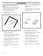
Страница 21: ...t adjustment hole 5 Pull the auger control cable 3 up through the cable adjustment bracket 2 6 Put the cable boot 1 over the cable adjustment bracket 2 2 1 7 Figure 6 Install the Z hook 1 to the auger drive lever 2 8 To check the adjustment start the snowthrower Make sure the auger does not rotate when the auger drive is released 1 2 2 3 4 HOW TO REMOVE THE BELT COVER 1 Figure 8 If equipped remove...

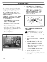
Страница 22: ...y from the drive belt 1 4 To reduce pressure on the drive belt 1 move the idler pulley 2 away from the drive belt 1 Remove the drive belt 1 from between the brake pad 3 and the roller 5 5 Remove the old drive belt 1 6 To install the new drive belt 1 reverse the above steps 7 Make sure the drive belt 1 is seated properly on the pulleys 8 Figure 10 Set the belt guide 1 to 3 32 clearance NOTE When th...

Страница 23: ... thrower 7 Tip the auger 2 enough to allow the auger 2 to slide out of the auger housing 6 8 To install auger 2 reverse the above steps 1 5 4 3 2 6 HOW TO ADJUST THE BRAKE PAD IMPORTANT An adjustment is only necessary if the brake pad has become loose or has been re moved to adjust proceed as follows 1 Remove the top cover See How To Remove The Top Cover 2 Remove the belt cover See How To Remove T...

Страница 24: ...re 4 Clean the area around the spark plug base to prevent dirt from entering the engine when the spark plug is removed 5 Remove the spark plug 1 6 Check the spark plug If the spark plug is cracked fouled or dirty it must be replaced 7 Figure 14 Set the gap between the elec trodes of the new spark plug at 030 inch Next install the spark plug in the cylinder head and firmly tighten Recommended torqu...

Страница 25: ...ne must be stored outdoors block up the snow thrower to be sure the entire machine is off the ground 10 Cover the snow thrower with a suitable protective cover that does not retain moisture Do not use plastic HOW TO ORDER REPLACEMENT PARTS Use only manufacturer s authorized or approved replacement parts Do not use attachments or accessories not specifically recommended for this unit In order to ob...

Страница 26: ...resh fuel Excessive vibration Loose parts damaged impeller Stop engine immediately and disconnect spark plug wire Tighten all bolts and make all necessary repairs If vibration continues have the unit serviced by a competent repairman Unit fails to propel itself Drive belt loose or damaged Replace drive belt Unit fails to discharge snow Auger drive belt loose or damaged Adjust auger drive belt repl...

Страница 27: ... torque specification chart 0003 The above parts group applies to the following Mfg Nos 4 2007 Copyright by Briggs and Stratton Corporation Briggs and Stratton Yard Power Products Group Milwaukee WI USA All rights reserved 6210530x37NA 5021R 6210540x37NA 5021E TP 400 4686 02 ST Q ...

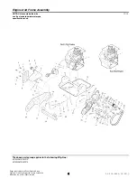
Страница 28: ...601 40 00 65 PLATE SUPPORT 23 601 50 51 41 FRAME RIGHT HAND 24 601 50 51 42 CHANNEL FRAME SUPPORT 25 601 50 51 43 FRAME LEFT HAND 26 601 50 51 44 ARM IDLER BLACK 27 601 00 13 31 BRAKE PAD 28 601 00 16 94 ROD CLUTCH LINKAGE 29 601 00 13 37 NUT 3 8 16 JAM CONTROL LOCK 30 601 40 00 75 WIRE BRAKE 31 601 50 51 45 PULLEY IDLER 32 601 00 13 33 PINCH ROLLER 33 601 50 51 46 SCREW 3 8 16 X 1 50 34 601 00 13...

Страница 29: ... torque specification chart 0003 The above parts group applies to the following Mfg Nos 6 2007 Copyright by Briggs and Stratton Corporation Briggs and Stratton Yard Power Products Group Milwaukee WI USA All rights reserved 6210530x37NA 5021R 6210540x37NA 5021E TP 400 4686 02 ST Q ...

Страница 30: ...CER DRIVE PULLEY 50 601 50 51 61 BOLT ENGINE PULLEY 1 4 28 X 1 28 51 601 50 51 62 BOLT 5 16 18 X 0 865 52 601 50 51 63 SCREW 25 20 X 062 WASHER HEX HEAD TAPTITE 53 601 00 14 45 The above parts group applies to the following Mfg Nos 7 2007 Copyright by Briggs and Stratton Corporation Briggs and Stratton Yard Power Products Group Milwaukee WI USA All rights reserved 6210530x37NA 5021R 6210540x37NA 5...

Страница 31: ...e torque specification chart 0005 The above parts group applies to the following Mfg Nos 8 2007 Copyright by Briggs and Stratton Corporation Briggs and Stratton Yard Power Products Group Milwaukee WI USA All rights reserved 6210530x37NA 5021R 6210540x37NA 5021E TP 400 4686 02 ST Q ...

Страница 32: ...13 81 NUT 1 4 20 HEX CONTROL LOCK 17 601 40 00 86 SPACER SLEEVE 18 601 00 20 87 PULLEY 19 601 00 20 95 COVER BELT 20 601 50 51 59 COVER BOTTOM 21 601 50 51 60 KEY SET 22 601 40 00 76 NUT 5 8 32 23 601 00 01 11 WASHER 640 X 1 1 X 05 24 601 40 00 44 PRIMER CARBURETOR 25 601 50 51 89 NUT 1 20 HEX KEPS 26 601 00 01 02 SWITCH IGNITION 45 DEGREE 27 601 00 13 58 HOSE PRIMER 9 5 28 601 50 51 65 PANEL CONT...

Страница 33: ...ue specification chart 0007 The above parts group applies to the following Mfg Nos 10 2007 Copyright by Briggs and Stratton Corporation Briggs and Stratton Yard Power Products Group Milwaukee WI USA All rights reserved 6210530x37NA 5021R 6210540x37NA 5021E TP 400 4686 02 ST Q ...

Страница 34: ...601 50 51 94 WIRE FORM HINGE 5 75 601 601 00 13 89 BOLT 5 16 18 X 1 25 CARRIAGE 602 601 00 13 90 WASHER FLAT 349 X 69 X 066 603 601 40 00 81 KNOB WING 604 601 40 00 69 NUT 5 16 18 605 601 50 51 29 SCREW 5 16 18 X 75 606 601 00 20 38 NUT 5 16 18 HEX CONTROL LOCK 608 601 40 00 85 The above parts group applies to the following Mfg Nos 11 2007 Copyright by Briggs and Stratton Corporation Briggs and St...

Страница 35: ...ue specification chart 0011 The above parts group applies to the following Mfg Nos 12 2007 Copyright by Briggs and Stratton Corporation Briggs and Stratton Yard Power Products Group Milwaukee WI USA All rights reserved 6210530x37NA 5021R 6210540x37NA 5021E TP 400 4686 02 ST Q ...

Страница 36: ... X 63 X 065 9 601 40 00 80 NUT 25 20 HEX CONTROL LOCK 10 601 40 00 86 BOOT CLUTCH SPRING 11 601 00 13 95 CABLE UPPER CONTROL 12 601 00 13 92 BRACKET CABLE ADJUST 13 601 00 13 93 CABLE LOWER CONTROL 14 601 00 13 94 SPRING EXTENSION 75 O D X 069 X 2 00 15 601 00 13 96 The above parts group applies to the following Mfg Nos 13 2007 Copyright by Briggs and Stratton Corporation Briggs and Stratton Yard ...

Страница 37: ...que specification chart 0009 The above parts group applies to the following Mfg Nos 14 2007 Copyright by Briggs and Stratton Corporation Briggs and Stratton Yard Power Products Group Milwaukee WI USA All rights reserved 6210530x37NA 5021R 6210540x37NA 5021E TP 400 4686 02 ST Q ...

Страница 38: ... WASHER FLAT 349 X 69 X 065 859 601 40 00 81 WASHER SPLIT LOCK 31 X 58 X 08 860 601 40 00 79 NUT 1 4 20 HEX 861 601 50 51 35 BRKT CHUTE ROTATE 870 601 50 51 85 BOLT 5 16 18 X 75 CARRIAGE 871 601 00 14 11 WASHER FLAT 349 X 69 X 065 872 601 40 00 81 WASHER SPLIT LOCK 31 X 58 X 08 873 601 40 00 79 NUT 5 16 18 HEX 874 601 50 51 29 The above parts group applies to the following Mfg Nos 15 2007 Copyrigh...

Страница 39: ...ecification chart 0015 The above parts group applies to the following Mfg Nos 16 2007 Copyright by Briggs and Stratton Corporation Briggs and Stratton Yard Power Products Group Milwaukee WI USA All rights reserved 6210530x37NA 5021R 6210540x37NA 5021E TP 400 4686 02 ST Q ...

Страница 40: ...0 00 11 DECAL HUSQVARNA 5021R Used on Model 6210530x37NA 5021R Only 5 601 40 00 16 DECAL HUSQVARNA 5021E Used on Model 6210540x37NA 5021E Only 5 601 40 00 15 DECAL WARNING HOT MUFFLER 6 601 40 00 77 DECAL AUGER CONTROL 7 601 50 51 79 DECAL DANGER CHUTE 8 601 40 00 67 DECAL DANGER AUGER FOOT 9 601 00 23 29 Note Not a serviceable part The above parts group applies to the following Mfg Nos 17 2007 Co...

Страница 41: ...ecification chart 0013 The above parts group applies to the following Mfg Nos 18 2007 Copyright by Briggs and Stratton Corporation Briggs and Stratton Yard Power Products Group Milwaukee WI USA All rights reserved 6210530x37NA 5021R 6210540x37NA 5021E TP 400 4686 02 ST Q ...

Страница 42: ...50 660 601 50 51 72 WASHER FLAT 391 X 1 00 X 125 661 601 50 51 71 RING RETAINER E 662 601 40 00 72 The above parts group applies to the following Mfg Nos 19 2007 Copyright by Briggs and Stratton Corporation Briggs and Stratton Yard Power Products Group Milwaukee WI USA All rights reserved 6210530x37NA 5021R 6210540x37NA 5021E TP 400 4686 02 ST Q ...

Отзывы: