background image

8

Operator's Manual

26750TSC Compact Tiller

For additional information email 

[email protected]

 or call 800-345-6007 M-F 8-5

 ImPORTaNT

THE RIGHT aND lEFT SIDES OF YOUR RO-

TOTIllER aRE DETERmINED FROm THE 

OPERaTING POSITION aS YOU FaCE THE 

DIRECTION OF FORWaRD TRaVEl.
ENGINE IS SHIPPED FROm FaCTORY WITH-

OUT OIl. YOU mUST aDD ENGINE OIl BE-

FORE STaRTING ENGINE.

 CaUTION

DO NOT TRY TO lIFT THE ROTOTIllER FROm THE  

CaRTON.

 FIGURE 1 

 FIGURE 2 

 FIGURE 3 

Highest Position

Lowest Position

Middle Position

M8 x 25 bolts

lower handlebar loop

M8 nuts

washers

upper handlebar

handlebar strap

lower 

handlebar loop

M8 hand 

knobs

M8 x 25 bolts

L

R

M8 x 20 bolts

UNPaCKING aND aSSEmBlY 

UNPaCKING aND aSSEmBlING YOUR TIllER

1.  Open top of carton and remove handlebar assembly.
2.  Parts bag for compact tiller contains:
  2- Bolts M8 x 1.25 x 20 Hex Head
  6- Bolts M8 x 1.25 x 25 Hex Head  
  6- Washers M8 8.4mm x 24mm x 2.2mm
  6- Nuts M8 x 1.25
  2- Middle Handlebar Straps
  2- Hand Knobs
  6- Bolts M6 x 1.0 x 12
  6- Nylock Nuts M6 x 1.0
3.  Remove machine from carton
4.  Assemble the upper handlebar onto the lower handlebar 

loop. Use the two (2) middle handlebar straps to connect the 

upper handlebar to the lower handlebar loop. Put the M8 x 

25 bolts through the six lower bolt holes from the outside in.  

Put on six (6) washers and tighten with six (6) M8 nuts on the 

six (6) bolts.  Tighten the two (2) M8 hand knobs on the two 

(2) M8 x 20 bolts in the upper most hole on each side of the 

handlebar. (

SEE FIGURES 1 aND 2) 

 The two (2) upper bolts 

and hand knobs can be used in one of three hole positions 

for handlebar height adjustability. 

SEE FIGURE 3

Содержание 26750TSC

Страница 1: ...Manual Original Operating Instructions 26750TSC Compact Tiller GAS OIL RATIO 50 1 P N 13461 ECN 9580 Rev 10 11 12 2012 Ardisam Inc All Rights Reserved Email for more information info ardisam com Produ...

Страница 2: ...ection Agency EPA This manual may contain information for several models Read and keep this manual for future reference This manual contains important information on SAFETY ASSEMBLY OPERATION AND MAIN...

Страница 3: ...operate this equipment Before Operating Engine Please read this section carefully Read entire operating and maintenance instructions AND the instructions in the engine manual that accompanies this pr...

Страница 4: ...light Do not operate product when fatigued or under the influence of alcohol drugs or other medication which can cause drowsiness or affect your ability to operate this machine safely Never operate m...

Страница 5: ...on monoxide can reach dangerous levels very quickly Never run engine outdoors where exhaust fumes may be pulled into a building Neverrunengineoutdoorsinapoorlyventilatedareawhere the exhaust fumes may...

Страница 6: ...idents can occur if the operator is not alert to the presence of children and or bystanders Never assume that others will remain where you last saw them Keep the area of operation clear of all persons...

Страница 7: ...er to you and others who may use the equipment Follow the safety instructions necessary for safe effective operation of your rototiller Part No 18091 WARNING Tine Shield Decal Part No LBL3100D CLUTCH...

Страница 8: ...r Tiller 1 Open top of carton and remove handlebar assembly 2 Parts bag for compact tiller contains 2 Bolts M8 x 1 25 x 20 Hex Head 6 Bolts M8 x 1 25 x 25 Hex Head 6 Washers M8 8 4mm x 24mm x 2 2mm 6...

Страница 9: ...RE 5 7 Installthedragstakeassemblyfromthetopdownthroughthe drag stake holder tube on the tiller frame between the wheels Lock the drag stake in place using the lock pin that is already affixed to the...

Страница 10: ...res drive safety control lever tines adjustable forward cable adjustable handlebar height adjustable depth regulator transport wheels ENGINE DISPLACEMENT 99cc tilling width 11 in 16 in 21 in tilling D...

Страница 11: ...ore adjustment can be made belt may need to be replaced Drag Stake Tillingdepthiscontrolledbytheheightofthedepthregulatorlever See Figure 8 To adjust tilling depth 1 Remove lock pin 2 Raise the depth...

Страница 12: ...e to return normally Repeat until engine starts 6 When engine starts gradually move choke lever to run position and increase throttle speed to the FAST position for tilling Important Engineisshippedfr...

Страница 13: ...ice tasks that are more difficult or require special tools are best handled by professionals and are normally performed by a technician or other qualified mechanic Maintenance replacementorrepairofthe...

Страница 14: ...r SEE FIGURE 9 Change Drive Belt 1 Turn off engine Engine must be cool 2 Remove spark plug wire from spark plug and secure 3 Remove top and lower belt guards 18129 and 18123 see figure 10 remove the b...

Страница 15: ...near by areas may exceed 150 F Avoid these areas Caution Do not operate tiller before reading the engine manual provided in the parts packet Important Engineisshippedfromfactorywithoutoil You must ad...

Страница 16: ...to neutral to start the engine Engine misses or lacks power Raise the tines for shallower tilling by raising the depth regulator lever Clean or replace air cleaner Improper carburetor adjustment take...

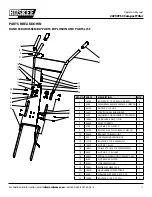
Страница 17: ...BAR MIDDLE 2 5 3359 WELDMENT HANDLEBAR FT PRO SERIES 1 6 13833 Handlebar Grip 1 in ID 2 7 53650 LEVER CONTROL 1 8 3248 Nut M5 x 0 8 HFNYLK 1 9 13159 Bolt 60D x 32 Shldr M5 x 7mm hh 1 10 53629 BRACKET...

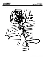
Страница 18: ...0TSC CompactTiller For additional information email info ardisam com or call 800 345 6007 M F 8 5 Engine assembly Parts explosion 26 27 25 27 26 21 22 9 30 17 18 19 20 15 5 6 7 4 1 11 11 24 8 2 23 13...

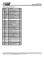
Страница 19: ...12 53596B YOKE ZINC PLATED CLEVIS 1 13 1416 PIN CLEVIS 1 14 1418 PIN COTTER 1 15 18015 WELDMENT CABLE GUIDE PLATE 1 16 1407 SPRING FORWARD ARM 1 17 18043 SHIM 25 IN ENGINE MOUNT 2 18 3245 WASHER M8 8...

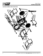
Страница 20: ...al 26750TSC CompactTiller For additional information email info ardisam com or call 800 345 6007 M F 8 5 5 9 8 11 16 12 15 3 8 11 14 22 23 17 7 6 2 13 13 11 1 10 7 4 8 20 21 8 18 21 19 Chassis assembl...

Страница 21: ...OLT M8 X 1 25 X 45 HHFCS GR8 8 ZN 2 10 400024 WASHER FLAT M8 8 4 X 16 X 1 6 THK GR8 8 ZN 2 11 W1200117 WASHER M6 X 13 X 1 75 FLAT ZN 6 12 18123 WELDMENT GUARD PULLEY LOWER 1 13 18103 BOLT M6 X 1 0 X 4...

Страница 22: ...LAT 16GA 1 11 1916965 WASHER 1 4 SPRING LOCK ZINC 1 12 13600 Bolt M6 x 1 0 x 25 HHF 9 13 W1265V0904 Bolt M8 x 1 25 x 20 HHCS ZN 1 14 13902 Bearing Ball 25mm Id 2 15 3220 Bearing Tapered Rolling 30204...

Страница 23: ...ted to negligent use misuse alteration ac cident unauthorized parts failure to use proper fuel and oil or if repairs have been performed at non authorized servicecenters Thesewarrantiessupersedealloth...

Страница 24: ...imate and are subject to change without notice Due to continuous product improvements product images may not be exact Items used for props not included Some assembly may be required For additional inf...

Отзывы: