


FORM NO. 41068-01 8/95
- 3 -
©1995 HUNTER FAN CO.
Step 6: Final Wiring
A.
Connect electrical supply leads to the leads from the motor,
using approved connectors.
1. Connect black electrical supply lead to the black motor lead
and the black with white stripe motor lead (see note).
2. Connect the white electrical supply lead to the white mo-
tor lead.
3. Connect the ground wire to the green leads.
NOTE: If a separate wall switch will be used to control a lighting
accessory, connect the black wire with a white stripe to the wall
switch lead, following wiring instructions included with the ac-
cessory. The wall switch must be acceptable for use as a general-
use switch.
CAUTION: No bare wire or wire strands should be visible after
making connections.
B.
After making the wire connections, all wires must be pushed
back up into the outlet box. The splices should be turned upward.
The wires should be spread apart with the white and the green
wires on one side of the outlet box, and the black and black/white
wires on the other side of the box.
NOTE: If the wires are not pushed up into the outlet box they
could strike the motor when it operates.
Step 7: Finish Fan Assembly
A.
Using two 8-32 by approximately 5/8" long screws, from sack
parts, thread the plastic hanger locking screws into the back of the
hanger bracket. See Figure 6. The screws should be driven all the
way into the bracket and tightened. The screws are located just
above the plastic hanger and prevent the motor from twisting when
the blades are assembled.
FIGURE 6
FIGURE 6A
Check and make sure all wiring is tucked up into the outlet box.
LOCKING
SCREWS
B.
Place the fan housing over the motor assembly and fasten the
housing to the ceiling plate using the four screws provided (two
each side). See Figure 6A.
ASSEMBLY
SCREWS
FAN
HOUSING
Check and make sure the motor clears the opening in the bottom
of the housing.
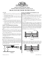
Step 8: Fan Blade Assembly, Installation,
and Balancing
A.
Attach wood blades to blade brackets using three screws for
each blade. See Figure 7. If your blades have large holes you must
first insert the rubber grommets into the holes. See Figure 7A.
NOTE: Grommets are usually assembled by hand. If you use a
tool, make certain you do not damage the grommet or blade when
inserting the grommets.
Next assemble the blade to the blade bracket. Make sure all screws
are tight to prevent vibration or wobbling. A cavity in the styrofoam
packaging has been provided to nest the parts in during assembly
to assure correct alignment of parts.
Even when the screws are tight, the blades may seem to be loose.
This is normal when using grommets and will not be a problem.
FIGURE 7
FIGURE 7A
BLADE
GROMMET
B.
If there are screws in the motor hub, remove them and use the
screws to attach the blades to the motor. If the motor does not have
screws, you will find them in sack parts.
Insert a mounting screw in hole in blade bracket. Use a screw-
driver to hold in place. Align blade holes with mounting holes in
hub by turning screw and readjusting blade bracket until screw
mates with threaded hole in hub. Do not tighten until both screws
have been put in blade bracket. Repeat for all blades. See Figure 8.


