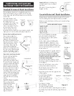
Standard Motorized Shade Installation
The installation brackets are supplied in pairs. One
bracket with locking ring is used for the motor-side
of the shade and one ball joint bracket is used for the
rotator side.
The roller shade can be
mounted inside or outside
the window frame, or
mounted to the ceiling. The
installation brackets are
always mounted so that the
inner surfaces face each
other as shown. It is very
important that the brackets are mounted correctly, with
clip in place, to insure safety and proper operation.
Rotator-Side Installation Brackets
Place shade spindle foot
into bracket with ball joint
(opposite of motor). Hold
the shade and bracket in the
desired position at window
and mark location on the
mounting surface. Set the
shade aside and drill the
bracket mounting holes. Use
the two screws provided (and
anchors if needed) to attach
bracket to mounting surface.
Motor-Side Installation Bracket
Remove locking ring from
brachet and set aside.
Fit spindle of shade into
previously mounted bracket,
fi t motor bracket snugly onto
motorized shade and hold in
desired location at window.
Before marking the bracket
location, make sure shade is
level. Mark position on the
mounting surface and set aside
shade to drill mounting holes.
Use the two screws provided
(and anchors if needed) to
attach bracket to mounting
surface.
Install the Shade Assembly
Place spring loaded
spindle (end opposite
motor) into ball
joint and compress
spring. Slide motor
end of shade into
opposite bracket.
PROFESSIONAL INSTALLER AND
ELECTRICIAN HIGHLY RECOMMENDED
Locking Ring
Bracket
Ball Joint Bracket
ROTATOR
PIN
CEILING MOUNT
INSIDE/OUTSIDE
MOUNT
MOTOR
INSIDE/OUTSIDE
MOUNT
CEILING MOUNT
• For Cassette Wall Mount Shades,
place the shade in the desired
mounting position, and mark the
top of the cassette.
• Set the shade side and utilizing the
enclosed template, measure 1” to 2”
in from the left and right edge of the
window. Mark that position at the same
level as the fi rst mark. Be sure the two
marks intersect.
• Using the template as a guide, measure
and mark the placement of the screws
for all necessary brackets.
THESE
BRACKETS MUST BE LEVEL AND
ALIGNED OR THE SHADE WILL NOT
FUNCTION PROPERLY.
(To use the template, fi nd the correct
shade type and mounting style areas on
the template.)
• Place the “Start Point” arrow at the
previously marked intersection.
• Mark the placements of the screw
indicated by the template.
• Repeat this process for the opposite side
of the window.
• For Wall Mount Shades,
the tab of the clip-in
bracket should be facing
down. (See diagrams A
and B)
• For Inside / Ceiling
Mount Shades, the tab of
the clip-in bracket should
face towards the window. (See diagrams A and C)
• Install the clip-in bracket with the proper fasteners
(screws).
Cassette Motorized Shade Installation
Remembrance motorized window shades with Cassette
mount utilizing the small clip-in brackets provided.
Shades may be installed as wall mount or inside/ceiling
mount shades.
CLIP-IN BRACKET CHART
Up to 36” shade
Up to 36” shade
3 brackets
36-1/8” to 60”
36-1/8” to 60”
5 brackets
60-1/8” to 72”
60-1/8” to 72”
6 brackets
72-1/8” to 84”
72-1/8” to 84”
7 brackets
84-1/8” to 108”
84-1/8” to 108”
9 brackets
108-1/8” to 120”
108-1/8” to 120”
10 brackets
Wall Mount
Tab
Lip
Clip-In
Bracket
Diagram A
Diagram B
Inside/Ceiling Mount
Inside/Ceiling Mount
Inside/Ceiling Mount
Inside/Ceiling Mount
Inside/Ceiling Mount
Inside/Ceiling Mount
Inside/Ceiling Mount
Inside/Ceiling Mount
Inside/Ceiling Mount
Inside/Ceiling Mount
Inside/Ceiling Mount
Inside/Ceiling Mount
Inside/Ceiling Mount
Inside/Ceiling Mount
Inside/Ceiling Mount
Inside/Ceiling Mount
Inside/Ceiling Mount
Inside/Ceiling Mount
Inside/Ceiling Mount
Inside/Ceiling Mount
Diagram C
Diagram D
Diagram D
Inside/Ceiling Mount
Wall Mount
Important!
Replace locking ring
around bracket to insure proper
operation.
Proceed to “Connecting Power
Supply” section.


