3
532821-2_A
ICE HELIX® SERIES
Installation Guide
2
|
Installing the Front Battery Cover and Gimbal Bracket
1. Align the gimbal bracket standoffs to the front openings in the handle. The bracket tab should
be facing down and toward the back of the shuttle.
NOTE:
Some models come with multiple gimbal brackets. Make sure to select the gimbal
bracket that corresponds with your control head.
2. Secure the gimbal bracket to the shuttle handle using two included #10 - 32 x 1/2" screws.
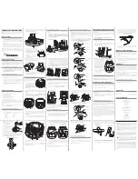
Hand-tighten only. See the illustration
Installing the Gimbal Bracket
.
3. Align the front battery cover with the grooves in the front of the shuttle base.
4. Thread the two tie-down straps on the bottom of the front battery cover through the slots in
the base. You will attach these to the back battery cover tie-down straps in a later step.
5. Slide the front battery cover snuggly into the grooves of the shuttle base.
6. Secure the front battery cover to the handle using the four included #8 – 32 x 3/8" screws and
#8 flat washers. See the illustration
Attaching the Front Battery Cover
.
7. From the back of the shuttle, secure the front battery cover to the bracket by inserting a #8 –
32 x 3/8" screw and #8 flat washer through the bracket tab and into the battery cover. See the
illustration
Attaching the Front Battery Cover
.
3
|
Installing the Battery and Connecting Power
1. Turn the shuttle on its side. Thread the two included battery tie-down straps from the bottom
of the base up through each side of the battery well, using the strap holes. Make sure the soft
side of the strap faces down.
NOTE:
There are two battery size options. Use the wider strap holes for the 20 volt battery
and the narrower strap holes for the 15 volt battery.
2. Turn the base right side up and pull up gently on the battery tie-down straps to remove the slack.
3. Move the tie-down straps out of the way so that the battery well is fully accessible.
4. Place the battery on the foam pad and push the battery into the battery well. Make sure that
the spade terminals are on the right side of the battery well and that the foam pad fits evenly
around the battery well edges. See the illustration
Installing the Battery
.
5. Slide the positive (red) spade connector from the power backbone onto the positive (red)
connector adapter on the charging cable (connected to the battery). Slide the negative (black)
spade connector from the power switch onto the negative (black) connector adapter on the
charging cable (connected to the battery).
WARNING!
Do not charge the battery and power the control head or other electronics at the
same time.
CAUTION!
Ensure that you connect the correct spade connector to the correct battery
terminal. Damage to the battery or device, or bodily harm may occur if the device is
improperly connected to the battery.
6. Pull the two battery tie-down straps over the top of the battery and connect both ends of each
strap over the top. Make sure that the straps are pulled tight around the battery, and that the
straps are not covering the battery LCD viewing window. Manage the power cables by routing
them under the straps.
7. Route the control head power cable from the power backbone through the cable pass-through window.
NOTE:
The power switch includes three SAE cables for auxilliary use. If used, the cables
connected to the SAE cable can be routed through the side grommets on the back battery
cover.
Attaching the Front Battery Cover
Installing the Gimbal Bracket
Installing the Battery
foam pad
spade
terminals

