

STEP 9: ROUTE CABLES
a
b
Note:
Cable Openings can
be used if wires need to
exit Track at certain
location
along the Track.
Cables
a. Route cables through the central channel of the Track which runs from
the Top Cap, through the Mounts and any Accessory Mount(s).
b. Route through the Bottom Cap, which allows room for most common
electrical plugs to pass through.
c. The M8 includes a cable management system to keep monitor cables organized and protected. Start by inserting cables into Cable Clip.
d. Route cables across the bottom of the Upper Arm and around to the top of the Lower Arm. Insert cables into groove on top of the Lower Arm. Place Arm Cover onto the
Lower Arm so that the grooves interlock. Slide Arm Cover up until it snaps in place.
Keyboard and Mouse Cables
Monitor Cables
e. The Keyboard includes a cable management system (underneath the Keyboard) to keep Keyboard cables organized and protected. Start by inserting cables into the top of
the Upper Arm.
f. Route cables across the bottom of the Upper Arm and around to the top of the Lower Arm. Insert cables into groove on top of the Lower Arm. Place Arm Cover onto the
Lower Arm so that the grooves interlock. Slide Arm Cover up until it snaps into place.
c
f
e
d
The following instructions are based upon the fact that Covers are designed to be installed in a specific orientation in order to minimize openings between Covers. Covers have
arrows on the back of them to indicate the top. A Cover should always go on top of the Cover below it. For this reason, it is recommended to install Covers starting at the
bottom and working up to the top.
Cutting Cable Covers to Size to Accommodate Accessory Mounts and Cable Openings
a. Snap the Cover at the desired location to break the plastic.
b. Using scissors or a blade, cut through the overmold layer between the crack that was created.
STEP 10: ATTACH CABLE COVERS
a
b
Attach Cable Covers
c. Align one side of the Cover inside of the Track channel.
d. Pushing at the top corner at the opposite side, feed the side into the channel, running the fingers down the side until the Cover is in place.
c
d
STEP 8: ATTACH ACCESSORY MOUNT TO TRACK (Optional)
a
b
c
d
e
f
g
in/lbs.
Attach Accessory Mount to Track
a. Vertically insert Accessory Mount into the Track cavity. Push down.
b. Rotate the Mount until it is horizontal.
c. The Spring Feet will engage, allowing the user to slide the Mount up or down to the desired position.
d. Using Hex Key C, you must tighten down the Friction Feet in order to complete installation of the
Accessory Mount to the Track. The Accessory Mount will not be able to support any weight if it is not
tightened down first. Feet must be tightened down to a torque of 30 in-lbs. [3.4 Nm] to ensure safe operation.
Note:
It is recommended to position the Mounts in a detent to allow for the best possible Cover fit in step 9.
Attach the Accessory Mount Cover to the Accessory Mount
e. Note the up arrow on the back of the Cover to determine which end is up.
f. Align one side of the Cover inside of the Track channel. Push in the Crush Rib on that side.
g. By pushing at the top corner at the opposite side, feed the side into the channel, running
fingers down the side and pushing in the Crush Rib at the bottom.
Note:
You must install the Accessory Mount Cover before attaching accessories otherwise the Cover
cannot be put onto the Track.
To remove the Accessory Mount, loosen the Feet (if necessary), push Accessory Mount into Track and
rotate to pull out.
Attach Monitor Arm
a. Remove Set Screws
on Arm Mounts.
b. Drop pin of Monitor Arm
and Keyboard Arm, or Solo
Arm into hole of upper Arm
Mount. Screw in the Set
Screw with Hex Key B.
c. After arms are in place screw
Set Screw back into place.
STEP 3: ATTACH MONITOR AND KEYBOARD ARMS OR SOLO ARM
a
x2
Example of Standard Arms
Example of Solo Arm
STEP 4: ATTACH KEYBOARD TRAY TO KEYBOARD ARM
a. Place Keyboard Tray on top of
Keyboard Arm and align holes.
b. Fasten Keyboard Tray to
Keyboard Arm using (4)
Keyboard Tray Installation
Screws.
c. Attach Palm Rest to Keyboard Tray.
STEP 5: ATTACH KEYBOARD TO KEYBOARD TRAY
a. Place (4) 3M Dual Lock Coins
on the underside of Keyboard.
b. Once attached, remove the film from
the exposed sides of Dual Lock Coins
and attach Keyboard Tray.
a
b
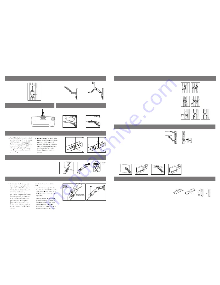
STEP 6: ATTACH VISA BRACKET TO MONITOR
STEP 7: ATTACH MONITOR TO MONITOR ARM
a. Slide VESA Bracket into Ball Joint until it clicks.
b. To remove, depress Quick-Release Tab and slide monitor up and away from Arm.
c. If security is required, tighten Security Screw using Hex Key A.
a
c
b
MONITOR WEIGHT ADJUSTMENT


