

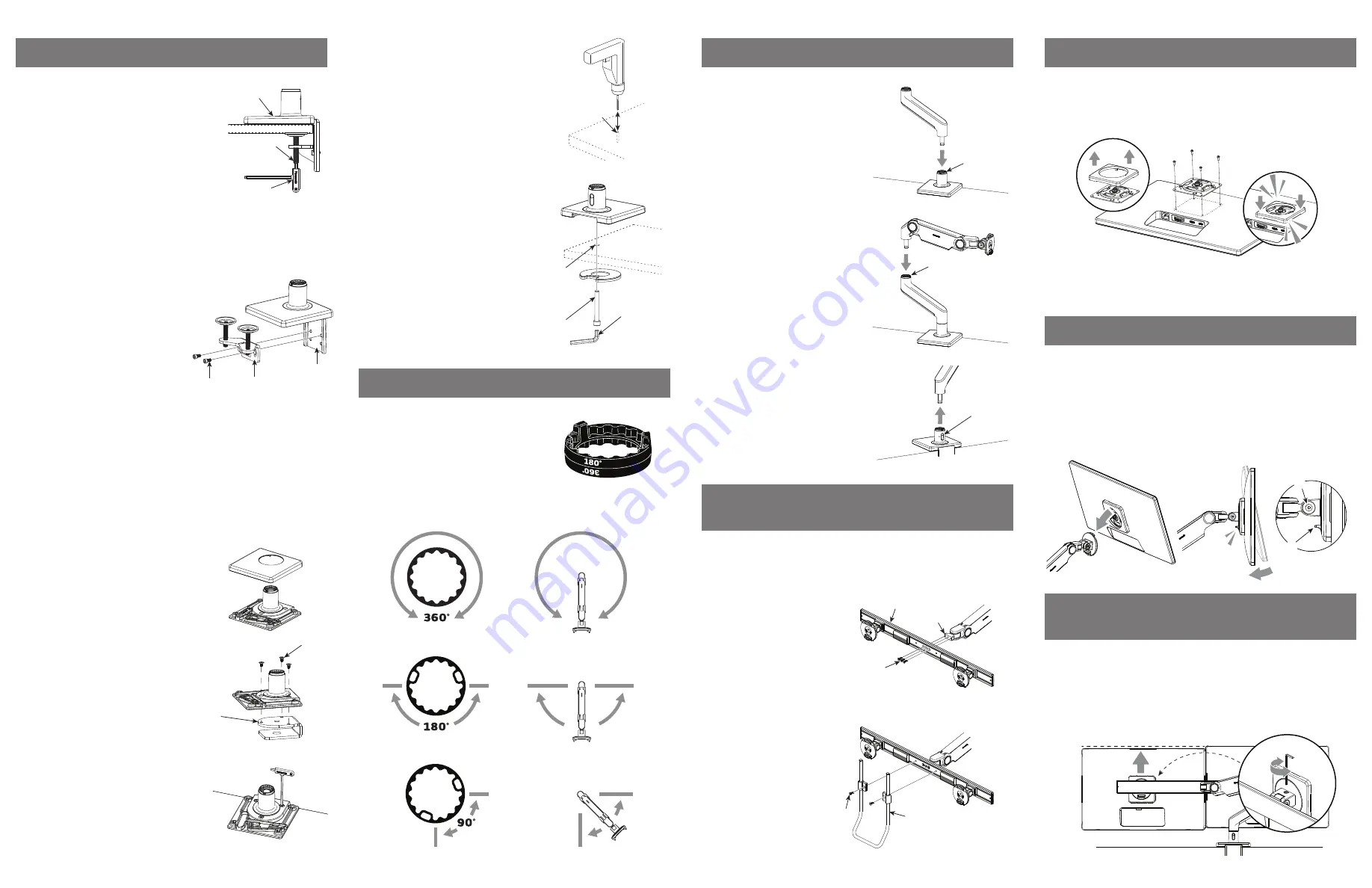
STEP 5: ATTACH VESA BRACKET TO MONITOR
STEP 7: LEVELING THE MONITORS
(DUAL-MONITOR APPLICATION ONLY)
STEP 6: ATTACH MONITOR TO ARM
A
B
1. Hold the monitor angled back and lower it onto the arm. Fit the hook at the top
of the arm into the corresponding cutout in the VESA Bracket.
2. Tilt the monitor back upright until the Quick Release Tab (B) on the arm
snaps into position.
3. To remove the monitor, lift the Quick Release Tab and pull the bottom of the
monitor away from the arm, then lift free of the hook.
NOTE
: If needed, adjust the tension screw (A) to hold the monitor in position.
After the monitors are installed on the crossbar, there may be a small height difference
between them. To align the monitors, use the adjustment screw located on top of the
monitor tilt.
1. To raise a monitor, turn the screw clockwise. To lower, turn counter clockwise.
2. If the adjustment bottoms out before reaching alignment, move the second
monitor in the opposite direction.
1. Separate the VESA cover from the VESA bracket.
2. Position the VESA Bracket over the mounting holes on the back of monitor with the
D-shaped cutouts in a vertical orientation. Attach using the 4 VESA screws provided.
3. Snap the VESA cover back in place.
The VESA Bracket features 75mm and 100mm hole patterns.
If you need to offset the Bracket from the monitor use the provided Extended VESA
screws and Plastic Spacers. You may also use the screws that came with your monitor.
STEP 3: ATTACH ARM TO BASE STEM
If using dual monitors, attach the crossbar according to the following steps. If using
triple monitors, use the instructions included with the triple crossbar. If using a single
monitor, continue to Step 5.
STEP 4: ATTACH CROSSBAR TO ARM
(DUAL-MONITOR APPLICATION ONLY)
2. (Optional) Attach handle (D) to
crossbar by using included
screws (E). Adjust the handle to
desired height. Tighten with
4mm hex key until secure.
1. Attach crossbar (A) to crossbar
link (B) using crossbar link
screws (C). Tighten with 4mm
hex key until secure.
NOTE
: Before adding each link, adjust the
smart stop (A) according to step 2. If using a
3 link configuration, one of the links must be
a 4” link. The link installation order may need
to be swapped so as to comply with step 2.
1. Insert the angled link into the mount
until release button locks in place.
2. Insert the dynamic link into the
angled link until the release button
locks in place.
3. To remove links, press the release
button (B) and lift upward near the joint.
A
B
C
E
D
A
A
B
J
K
L
BOLT-THROUGH MOUNT
1D. For installation on work surface with no
access for clamp system:
i. Drill 1/2" hole through work surface in
desired location.
NOTE:
Bolt-Through Mount can accommodate
a hole up to 4” (102mm) in diameter. If hole
is 2” (51mm) or more, cables can be routed
through the hole. For some 2”grommet
holes, cables should be routed before
installation of mount to accommodate cable
plugs (cable access is approximately 1.5” x
0.25” with 2” grommets).
ii. Position the M10 Base over the work
surface hole (J).
iii. Align Bolt-Through Plate, foam side up,
under the work surface. Pass the Bolt (K)
through the hole in the plate and screw
into M10 base by using 8mm hex key (L).
J
STEP 2: SMART STOP ADJUSTMENT
In each arm connection, there is an adjustable Smart
Stop Ring which can be positioned to limit the arm’s
range of motion. Depending on the orientation of the
ring the arms can be set to rotate either 90°, 180°,
or 360°. The marked angle will be in the center of
the range of motion. The stop rings must be
configured in such a way that the dynamic link head
does not pass behind the rear edge of the unit.
Arm can rotate
without stopping
Arm can rotate 180˚
Arm can rotate 90˚
STEP 1: ATTACH MOUNT TO WORK SURFACE
CLAMP MOUNT
NOTE:
There are two sets of Bracket Screw
holes to accommodate the thickness of every
work surface. Use the upper holes for surfaces
up to 1.8” (48mm) thick and lower holes for
surfaces up to 2.7” (68mm) thick.
1A. For installation on open edge of
work surface:
i.
Slide Mount (A) against work surface
edge and fully tighten Clamp screws(B)
with 5mm hex key (C).
1B. For installation on work surface
positioned against a wall or panel:
NOTE:
This method can also be used to
mount through grommet holes wider than 3”
i. Detach the Bottom Clamp (D) from the Top
Bracket (E) by loosening Bracket Screws
(F) with 5mm hex key.
ii. Position the Top Bracket against work
surface edge.
iii. Underneath the work surface, reattach
the Bottom Clamp to the Top Bracket
using the Bracket screws.
iv. Fully tighten the Clamp Screws (G) with
5mm hex key.
NOTE:
Clamp Mounts cannot be used to
mount the M10 to any vertical surface.
SLIDING DESK MOUNT
1C. For installation on a desk with minimal
clamp clearance:
i. Remove Base Cover.
ii. Loosely attach Clamp Bracket (H) to base
with three included screws (I). The screws
should not be tightened all the way.
iii. Slide the base and clamp over the back
edge of the work surface until the clamp
rests on the edge.
iv. Fully tighten the three clamp screws to
secure the base to the work surface.
A
B
C
F
D
E
H
I


