background image

12

Controls and Features (cont.)

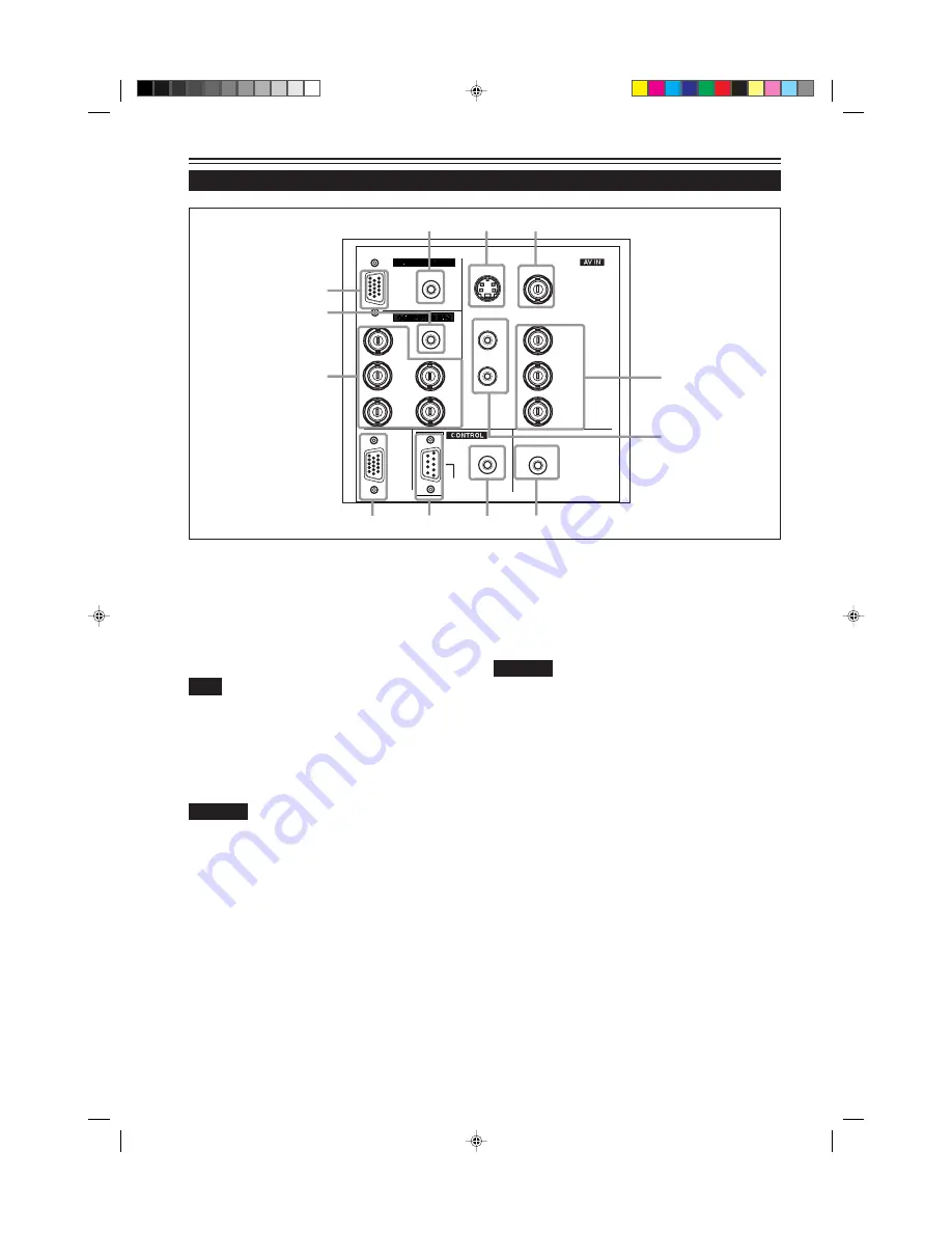
Connector Panel (Cont.)

9

COMPUTER IN (computer input) -2 terminal (BNC)
These are input terminals for analog RGB signals, vertical
sync (V) signals, and horizontal sync (H) signals /
composite signals(Cs). Devices which have analog RGB
signal output terminals can be connected.
 * Input of external sync signals is automatically

detected.

Detection of H/V signals or Cs signals causes automatic

switch to external sync. The priority order is H/V > Cs.

Note

• DTV-format (480i, 480p, 720p, 1080i) signals can be input.

When the source is set to “AUTO”, signals of 480i and 1080i can
automatically be detected, but 480p and 720p signals can not be
detected.
To be able to input 480p or 720p signal, the source should be set
to a dedicated source mode “SDTV(480p)” or “HDTV(720p)”. For
setting the source, refer to “Changing (setting) the source” on

page 47.

CAUTION

• When computer-related signals are input, the uppermost

edge of the screen may appear bowing if the sync signal
input is composite sync (Cs) or G on sync signal. In that
case, use separate sync signals for vertical sync (V) and
horizontal sync (H).

p

AUDIO input terminal (stereo mini jack)
This is an audio input terminal for COMPUTER IN
(computer input) -2 terminal. Connect the audio output
signal of a device connected to COMPUTER IN (computer
input) -2 terminal.
* When input to COMPUTER -2 is selected, the audio signal

input is reproduced by  the projector’s speakers. Also,
signals can be output from the AUDIO OUT (audio output)
terminal.
(However, if a cable is connected to AUDIO OUT (audio
output) terminal, audio sound does not come out from
the projector’s speakers.)

q

COMPUTER IN (computer input) -1 terminal (D-sub 3-
row 15 pin)
This is an input terminal (PC) dedicated for computer
signals (RGB video signals and sync signals).
Connect the display output terminal of the computer to this
terminal. When a Macintosh computer is to be connected,
use the Conversion adapter for Mac supplied.

CAUTION

• When computer-related signals are input, the uppermost

edge of the screen may appear bowing if the sync signal
input is composite sync (Cs) or G on sync signal. In that
case, use separate sync signals for vertical sync (V) and
horizontal sync (H).

w

AUDIO (audio) input terminal (stereo mini jack)
This is an audio input terminal for COMPUTER IN
(computer input) -1 terminal. Connect the audio output
signal of a device connected to COMPUTER IN (computer
input) -1 terminal.
* When input to COMPUTER -1 is selected, the audio signal

input is reproduced by  the projector’s speakers. Also,
signals can be output from the AUDIO OUT (audio output)
terminal.
(However, if a cable is connected to AUDIO OUT (audio
output) terminal, audio sound does not come out from
the projector’s speakers.)

Y

PC

AUDIO

AUDIO

AUDIO

AUDIO OUT

REMOTE

Y/C

VIDEO

Y

P

B

/B-Y

P

R

/R-Y

L

R

H/C

S

V

R

G

B

COMPUTER

OUT

RS-232C

w

1

2

q

p

9

8

7

6

5

3

4

G2000  p.05-14

99.11.20, 3:28 AM

12

Содержание G2000

Страница 1: ...rmation for future reference Pour l utilisateur Inscrivez ci dessous le No de série situé sur le panneau latéral du coffret de l appareil Conservez cette information à titre d information OPERATE VOL PAGE BACK PRESET ZOOM FOCUS COMPUTER VIDEO QUICK ALIGN AV MUTING W T MENU ENTER RM M100 REMOTE CONTROL UNIT Model No No de modèle G2000 Serial No No de série ENGLISH FRANÇAIS G2000 Cover A4 99 11 19 1...

Страница 2: ...G2000 Cover A4 99 11 19 10 42 PM 4 ...

Страница 3: ...1 ENGLISH DIGITAL GRAPHICS PROJECTOR G2000 INSTRUCTIONS G2000 SubcoverEN 99 11 20 3 27 AM 1 ...

Страница 4: ...wall outlet before cleaning Do not use liquid cleaners or aerosol cleaners Use a damp cloth for cleaning Do not use attachments not recommended by the product manufacturer as they may be hazardous Do not use this product near water Do not use immediately after moving from a low temperature to high temperature as this causes condensation which may result in fire electric shock or other hazards Do n...

Страница 5: ...service When replacement parts are required be sure the service technician has used replacement parts specified by the manufacturer or with same characteristics as the original part Unauthorized substitutions may result in fire electric shock or other hazards Upon completion of any service or repairs to this product ask the service technician to perform safety checks to determine that the product ...

Страница 6: ...ected to the Projector 25 Basic Operations 26 1 Turning on the Power 26 2 Select the video input to be projected 27 3 Adjust the screen size 27 4 Adjust focus 28 5 Adjust sound volume 28 For Operating Other Functions 29 Operating the Setting Menu 32 Making Basic Settings 32 Operating the Main Menu 33 Configuration of the Main Menu 33 Operating the Main Menu Basic Operation of the Main Menu 35 Chan...

Страница 7: ...x 2 m 6 56 ft D sub 3 row 15 pin Conversion adapter for Mac for Macintosh Audio cable approx 3 m 9 84 ft 3 5 mm dia stereo mini plug AV connection cable approx 1 5 m 4 92 ft BNC RCA conversion plug Accessories The following accessories are included with this projector Check for them if any item is missing please contact your dealer G2000 p 05 14 99 11 20 3 28 AM 5 ...

Страница 8: ...operating with the remote control aim it toward this sensor You can also operate the remote control by pointing it to a screen and allowing the remote sensor to receive the reflected light 3 AC IN power input terminal This is the power input terminal where the supplied power cord is connected For details refer to page 24 4 Fuse holder A fuse rated 15A 250V is installed Power source protection To r...

Страница 9: ...t position when shipped from the factory Turn the foot to make the projector level Adjustment can be made in the range of 1 5 and 1 5 from the horizontal position S TA N D B Y LA M P TE M P E M E R G E N C Y V ID E O C O M P U TE R S E TT IN G Q U IC K A LI G N 2 3 e r w 1 5 1 5 Shorten How to extend the adjustable foot on the rear While raising the projector turn the adjustable foot to the right ...

Страница 10: ...fect causing heat to build up inside which could cause a fire or malfunction t y u i y Opening for replacing the light source lamp For replacing the light source lamp refer to Replacing the Light Source Lamp on page 61 u Fixing foot i Position selecting screw for ceiling mounting When using the projector in an upside down ceiling mounted position inverted top to bottom and right to left the positi...

Страница 11: ...lace the lamp Refer to Replacing the Light Source Lamp on page 61 5 TEMP indicator ON The temperature inside the projector has abnormally risen Note While the TEMP indicator is on during abnormal temperature the power is automatically cut off and an emergency mode is shown with the EMERGENCY indicator blinking 6 EMERGENCY indicator Blinking Something abnormal has occurred with the projector Memo A...

Страница 12: ...ustment is finished the display goes off automatically Memo The quick alignment function Works for computer input COMPUTER 1 and 2 input terminals signals Does not work for video input AV IN input terminal signals CAUTION Automatic adjustment with the quick alignment function should be done on a bright still picture screen This function may not work correctly on a dark screen or motion picture scr...

Страница 13: ...Memo To select the proper audio input for video input The video input terminals AV IN input terminals can be switched with the projector s or remote control s VIDEO button However since this projector has only single audio input terminal reconnect audio input in accordance with the AV device to be used Controls and Features cont Connector Panel 5 AUDIO OUT audio output terminal stereo mini jack Of...

Страница 14: ...UTER 2 is selected the audio signal input is reproduced by the projector s speakers Also signals can be output from theAUDIO OUT audio output terminal However if a cable is connected to AUDIO OUT audio output terminal audio sound does not come out from the projector s speakers q COMPUTER IN computer input 1 terminal D sub 3 row 15 pin This is an input terminal PC dedicated for computer signals RGB...

Страница 15: ...al settings and does not work for switching ON to OFF q PAGE BACK button While a details setting is displayed use this button to go back to the previous page w VOL Volume button Use these buttons to adjust the sound volume Increase the volume level Decrease the volume level e OPERATE button To turn on the power press this button for one second or more About 30 seconds after the power has turned on...

Страница 16: ...mix new and old batteries Do not mix different types of batteries as they differ in characteristics Place batteries so they match the polarities indicated to and to Be sure to put the minus end in first to avoid short circuiting Use only designated batteries Remove the batteries if not used for a prolonged period of time When the batteries are exhausted replace them immediately Otherwise liquid co...

Страница 17: ...tor When the projector is enclosed in a space of the following dimensions use an air conditioner so the temperature inside becomes equal to the outside temperature Allowable minimum space required CAUTION Do not install the projector in the following places There is much water humidity or dust The projector may be subjected to oil smoke or cigarette smoke On a soft surface such as a carpet or cush...

Страница 18: ...r edge of the projected picture aligns with the extended center line of the projector s lens That way the lower edge of the picture projected on a 4 3 aspect ratio screen aligns with the extended center line of the lens Also the screen must be at right angles with the extended center line of the lens so that projection occurs at right angles with the screen When installing the screen use a 4 3 asp...

Страница 19: ...m Projection distance Projection screen size diagonal length Minimum projection screen size Tele end Maximum projection screen size Wide end For 16 9 aspect ratio screens 8 2 ft 2 5 m 39 approx 100 cm 57 approx 144 cm 9 84 ft 3 0 m 47 approx 120 cm 69 approx 175 cm 13 12 ft 4 0 m 63 approx 161 cm 93 approx 236 cm 16 4 ft 5 0 m 79 approx 201 cm 117 approx 297 cm 19 68 ft 6 0 m 95 approx 242 cm 140 ...

Страница 20: ...g must be turned to switch to ceiling mounting This will correct variance in color images shading which otherwise would occur in ceiling mounting To revert to normal desltop setting turn the position selecting screw for ceiling mounting back to the initial position factory shipped When using the projector in an upside down ceiling mounting position inverted top to bottom and right to left Turn the...

Страница 21: ...PAL 3 High vision signal Y PB B Y PR R Y G B R H CS V Screen resolution standard name Horizontal frequency Vertical frequency Scanning method 640 400 PC 9801 24 8kHz 56 4Hz Non interlace 640 350 VGA1 31 5kHz 70 1Hz Non interlace 640 480 VGA3 31 5kHz 59 9Hz Non interlace 640 480 Macintosh 13 35 0kHz 66 7Hz Non interlace 640 480 VGA VESA 37 5kHz 75 0Hz Non interlace 800 600 SVGA1 37 9kHz 60 3Hz Non ...

Страница 22: ... device thoroughly Use separately available BNC cables and audio cables to connect Hi Vision devices Y AUDIO AUDIO OUT REMOTE Y C VIDEO Y PB B Y PR R Y L R V RS 232C To AUDIO R To AUDIO L Audio cable separately available To VIDEO To Y To PB B Y To PR R Y BNC cable separately available To select the proper audio input for video input The video input terminal AV IN input terminal can be switched wit...

Страница 23: ...lt in amplifier Audio cable supplied or stereo mini plug Game device etc PC AUDIO AUDIO AUDIO REMOTE Y C L R H CS V R G B COMPUTER OUT RS 232C Desktop type Note type To RS 232C connector To RS 232C connector RS 232C reverse connection cable separately available To REMOTE terminal Infrared remote sensor extension unit Needs to be made To RS 232C connector To VIDEO To AUDIO L To AUDIO R To AUDIO OUT...

Страница 24: ... LCD to work if an external display is connected With such a note type the LCD display and external display output need to be switched To monitor connector RGB output devices Laser video disc player etc When connecting an audio output terminal such as a computer sound source to the projector connect to theAUDIO terminal using the supplied audio cable Computer cable supplied To COMPUTER IN 2 Separa...

Страница 25: ...op type Connecting to Various Devices Cont PC AUDIO AUDIO AUDIO REMOTE Y C L R H CS V R G B COMPUTER OUT RS 232C When connecting an audio output terminal such as a computer sound source to the projector connect to the AUDIO terminal using the supplied audio cable Other connections are the same as in the connection example for IBM PC or IBM compatible PCs Conversion adapter for Mac supplied Persona...

Страница 26: ...damage or work on the power cords Also do not put a heavy object on heat or pull the power cords otherwise they may be damaged Do not insert or pull out the plugs with a wet hand 1 Insert the supplied power cord into the power input terminal AC IN of the projector 2 Insert the plug of the supplied power cord into a wall outlet 1 2 AC IN Connecting the Power Cord Supplied CAUTION Since the power re...

Страница 27: ...nning During this time do not turn off the main power switch After the cooling of the light source lamp is finished the fans stop and the STAND BY indicator comes on then turn off the main power switch If you press the OPERATE button immediately after the light source lamp lights it takes about 40 seconds for the lamp to go off To turn the lamp on again wait 10 seconds or more before pressing the ...

Страница 28: ...ATE button for one second or more The STAND BY indicator changes to blinking and the projector goes into cool down mode 2 Turn off the MAIN POWER switch after the STAND BY indicator changes to steady on OFF The MAIN POWER switch turns off and the STAND BY indicator goes off 2 1 1 2 Remote control unit Projector or Example of the projector s button Projector Projector 2 1 1 Turning on the Power STA...

Страница 29: ...ns To enlarge the screen size Press the ZOOM W button To reduce the screen size Press the ZOOM T button Remote control unit Note The adjustment of the screen size zoom adjustment can also be made on the setting menu For operating the setting menu refer to Making Basic Settings on page 32 Press the VIDEO button or the COMPUTER button to switch the input Each time you press either button the selecte...

Страница 30: ...you press the VOL button The sound volume becomes higher 0 50 When you press the VOL button The sound volume becomes lower 50 0 When you press either button the corresponding AUDIO VOL level is displayed on the screen the display will disappear in about five seconds Remote control unit Note Sound volume can be adjusted on the setting menu For operating the setting menu refer to Making Basic Settin...

Страница 31: ...ctor s QUICK ALIGN 3 and 2 buttons at the same time During the automatic adjustment QUICK ALIGNMENT appears on the screen and disappears automatically after the adjustment is completed Note This function works only for computer system inputs It does not work for AV inputs CAUTION When performing automatic adjustment using the quick alignment function Use a bright still picture screen It may not fu...

Страница 32: ...SE H POS V POS FOCUS ZOOM and AUDIO VOL of the video picture being projected after installation connection or after inputs are switched For operating the setting menu refer to Making Basic Settings on page 32 Press the projector s SETTING button The setting menu is displayed on the screen MENU ENTER Note To change the menu language displayed English is set when the projector is shipped from the fa...

Страница 33: ...sed on the upper right corner of the screen Also the channel can be switched to another channel For details refer to Changing Channels page 54 When no menu is shown press PAGE BACK button on the remote control The channel is displayed on the upper right corner of the screen Remote control unit Note Before you can operate the projector channels must be set up beforehand For details refer to Setting...

Страница 34: ... See pages 29 38 and 39 1 Press the SETTING button of the projector The setting menu is displayed on the screen 2 Press the SETTING button to select the desired item The selected item is shown in magenta color Each time you press the button the selected item changes as follows TRACKING PHASE H POS V POS Menu clearing AUDIO VOL ZOOM FOCUS Memo To select items using the remote control unit Items can...

Страница 35: ...lor can be selected from BLUE CYAN BLACK GREEN MAGENTA RED and YELLOW COLOR TEMP Adjusts the color temperature of the image being projected Make adjustment when the image becomes reddish or bluish Color temperature can be set to LOW MIDDLE or HIGH ASPECT CHANGE Selects the vertical to horizontal ratio of the image projected The factory set ratio is 4 3 When projecting high vision video image a rat...

Страница 36: ...be selected from BLUE CYAN BLACK GREEN MAGENTA RED and YELLOW COLOR TEMP Adjusts the color temperature of the video image being projected Make adjustment when the video image becomes reddish or bluish Color temperature can be set to LOW MIDDLE or HIGH ASPECT CHANGE Selects the vertical to horizontal ratio of the video image projected The factory set ratio is 4 3 When projecting high vision image a...

Страница 37: ...ignal name to display can be selected from a submenu Source Setup AUTO mode dedicated mode forced mode or USER mode can be selected Channel display The channel selected by the user is dis played Channels have lines sources and switcher numbers registered By specifying a registered source the user can switch to the source and line which he has set up If you are using a switcher you can also specify...

Страница 38: ...ut is automatically identified NTSC 480i Dedicated to NTSC 480i NTSC4 43 Dedicated to NTSC4 43 PAL Dedicated to PAL SECAM Dedicated to SECAM Memo About automatic signal identification AUTO is selected when shipped from the factory In AUTO the color system DECODER of the signal being input is automatically identified and indicated in Display example AUTO NTSC 480i If operation in AUTO is unstable s...

Страница 39: ...anguage changes as follows 3 Forward 2 Backward Japanese English German Spanish Italian French Memo About language display English is selected when the projector is shipped from the factory The languages in the menu display are the following six Japanese ENGLISH DEUTSCH German ESPAÑOL Spanish and FRANÇAIS French However some displays such as Channel User Source Setup Display Size and Quick Alignme...

Страница 40: ...k for correct tracking adjustment To reset to the factory set adjustment values press the remote control s PRESET button Tracking and phase are reset to the factory set adjustment values To return to the main menu press the PAGE BACK button To finish the main menu press PAGE BACK again To finish the menu display from the submenu display PIXEL CLOCK menu press PAGE BACK twice The screen shrinks lat...

Страница 41: ...t adjustment values press the remote control s PRESET button H POS and V POS are reset to the factory set adjustment values To return to the main menu press the PAGE BACK button To finish the main menu press PAGE BACK again To finish the menu display from the submenu display POSITION menu press PAGE BACK twice The screen moves to the left 255 0 255 The screen moves to the right 255 0 255 The scree...

Страница 42: ...t PICTURE menu PICTURE menu When computer related signals are input 4 Select the item to adjust with the cursor button 5 or The items to adjust shown in text is displayed in magenta color Remote control unit Main menu Notes The selected item is shown in magenta color Items shown in gray color cannot be operated or set in the current mode Adjustment items on the PICTURE menu are different when AV s...

Страница 43: ...eat steps 4 and 5 To reset all items to factory set adjustment values 0 select ALL RESET with the cursor buttons and press the MENU ENTER button To reset only the selected items ALL RESET excluded to the factory set adjustment value press the remote control s PRESET button The selected item is reset to the factory set adjustment value Gets darker 30 0 30 Gets brighter 30 0 30 Gets lower 30 0 30 Ge...

Страница 44: ...RAST 0 changing CONTRAST to 1 changes the adjustment values as follows R GAIN 1 G GAIN 6 and B GAIN 1 Also when the adjustment value of any of R GAIN G GAIN and B GAIN has reached 30 minimum or 30 maximum CONTRAST cannot be adjusted to any higher value For example when R GAIN is 0 G GAIN is 5 B GAIN is 0 and CONTRAST is 0 increasing CONTRAST allows the other adjustment values to increase until R G...

Страница 45: ... press the remote control s PRESET button The treble and bass are reset to the factory set adjustment values To return to the main menu press the PAGE BACK button To finish the main menu press PAGE BACK again To finish the menu display from the submenu display SOUND menu press PAGE BACK twice Gets weaker 5 0 5 Gets stronger 5 0 5 Gets stronger 5 0 5 Gets weaker 5 0 5 Adjustment item Button Adjustm...

Страница 46: ...em displayed in text is shown in magenta color on the screen 3 Press the MENU ENTER button The submenu items of the OPTIONS menu are displayed OPTIONS menu Remote control unit Main menu Note The selected item is shown in magenta color Items shown in gray color cannot be operated or set in the current mode Items to be set adjusted are different when AV signals are input and when computer system sig...

Страница 47: ... Inverses video image upside down Factory setting OFF OFF For normal set up ON For upside hanging from the ceiling OFF ON Sets the clamp pulse s position at the back porch BP or on the sink tip ST Normally the clamp is used at BP If with some PCs or workstations the screen becomes unstable such as being too dark or too bright try to switch to ST factory setting BP BP The clamp pulse is positioned ...

Страница 48: ... PAL SECAM 16 9 The aspect ratio of the screen becomes 16 9 Set it to 16 9 for Hi Vision devices W VHS VCR etc 4 3 16 9 Sets the length of sleep time which automatically brings the projector into stand by state You can select one of the following sleep times You can select one of the sleep times 10 20 30 60 and 0 minutes Factory setting 30 minutes 10 20 30 60 0 If you select 0 minutes this functio...

Страница 49: ...may work possibly causing the screen to be intermitted or disturbed In that case set to a dedicated source forced mode When special effect playback fast forward twice speed triple speed is performed on a video deck etc the picture may be disturbed or intermitted depending on the device When inputting 480p or 720p DTV format signal in COMP 2 input mode use the dedicated source mode SDTV 480p or HDT...

Страница 50: ...PAL SECAM PC 98 VGA1 VGA3 MAC13 VGA VESA SVGA1 SVGA2 MAC16 XGA1 XGA2 MAC19 MAC21 SXGA1 SXGA2 SXGA3 USER C H 1 C O M P 2 S X G A 1 SOURCE SXGA1 AUTO NTSC 480i SDTV 480p HDTV 720p HDTV 1080i PAL SECAM PC 98 VGA1 VGA3 MAC13 VGA VESA SVGA1 SVGA2 MAC16 XGA1 XGA2 MAC19 MAC21 SXGA1 SXGA2 SXGA3 USER Source When USER is selected The USER SOURCE SETUP menu is displayed This menu is used when registering and...

Страница 51: ...when a channel is selected incoming signal is automatically checked and switched to one of the sources registered on the channel If a matching source is not found among the registered sources all other available sources are searched to find a matching source 1Press the MENU ENTER button The main menu appears on the screen 2Select the CHANNEL with the cursor button 5 or The selected item displayed ...

Страница 52: ...ou choose a channel using such as a direct channel 7 Press the MENU ENTER button to set fix The display returns to the CHANNEL setup menu After setting a LINE item SOURCE and SWNo items can be set Y C V I D E O Y P B P R C O M P 1 C O M P 2 N O N E L I N E Line selection menu To return to the main menu press the PAGE BACK button To finish the main menu press PAGE BACK again To delete the contents ...

Страница 53: ...eck mark and press MENU ENTER the check mark will disappear canceling its registration as a SOURCE item When a channel is selected the registration or setting of its contents cannot be cleared When USER is selected from the SOURCE SETUP menu The USER SOURCE SETUP menu appears The registered user source names are indicated with check marks The source set up on the USER SOURCE SETUP menu is used for...

Страница 54: ...e MENU ENTER button to set When the item is set a check mark is placed next to its user name which is registered as a SOURCE If you place the cursor on a SOURCE item with a check mark attached and press MENU ENTER button the check mark will disappear making the item unregistered as a SOURCE item To return to the main menu press the PAGE BACK button To finish the main menu press PAGE BACK again G20...

Страница 55: ... the number larger If you select 77 any SWNo item is not registered If a channel is selected you cannot make any settings or changes 4Press the PAGE BACK button When you press PAGE BACK the switcher number is set and the display returns to the CHANNEL setup menu Be careful that if you set the same switcher number to a few channels and operate using the switcher number the youngest number channel i...

Страница 56: ...g menu 2 Select the Channel number with the cursor button 5 or Numbers that you can choose from are numbers from 1 to 10 and AUTO Pressing the cursor makes the number smaller Pressing the cursor 5 makes the number larger If you press PAGE BACK the selection will be canceled 3 Press the MENU ENTER button to set fix The display switches automatically to the line and source that are set for the chann...

Страница 57: ...7 CH LINE SOURCE SWNo Channel Setup Selection menu Submenu item CHANNEL Main menu 4Press the cursor button 5 or to select a channel CH you want to switch to The selected CH is shown in magenta color 5Press the MENU ENTER button to set fix The line input source and switcher number that are registered to the channel are selected Y C C H 1 N T S C 4 8 0 i Line Source Channel Memo To be able to select...

Страница 58: ...lect USER SOURCE SETUP The selected item text display is shown in magenta color 3 Press the MENU ENTER button A submenu USER SOURCE SETUP menu is displayed on the screen A 7 is displayed for any No where no user source is registered User Source Setup menu USER1 HD1035i_R HD1035i_Y USER SOURCE SETUP 1 2 3 4 5 6 7 8 9 10 No USER NAME 4 Press the cursor button 5 or to select a new number you want to ...

Страница 59: ...ss the cousor button 3 to move to USER NAME The selected item text display is shown in magenta color To be able to select USER NAME a source must already be set up Notes The selected item is shown in magenta color Items shown in gray color cannot be operated or set in the current mode To set up change user names 1Press the MENU ENTER button The main menu appears on the screen 2Press the cursor but...

Страница 60: ...er name is displayed on the USER NAME item on the screen USER1 USER NAME 1 Press the cursor button 2 or 3 to select positions where to enter characters Up to 9 input positions can be selected 2 Press the cursor button 5 or to select characters to enter You can select any characters from A to Z 0 to 9 _ and space 3 Repeat steps 1 and 2 to enter the user name Up to 9 characters can be entered 4 Pres...

Страница 61: ...ay is shown in magenta color 3Press the MENU ENTER button to set fix Asubmenu DISPALAY SIZE is shown on the screen Display Size adjustment menu H PIXEL V PIXEL H CENTER V CENTER DISPLAY SIZE USER1 1152 870 60 24 The image display size the numbers of horizontal vertical effective dots and horizontal vertical display positions of the input signals sources registered in the user source setup can be a...

Страница 62: ...e you purchased your projector Fuse 15A 250V 1Turn off the main power switch and disconnect the power cord from both the projector and the wall outlet Place the main power switch to the OFF position 2Loosen the fuse holder to remove it To loosen the fuse holder use a Philips screwdriver 3Remove the fuse from the fuse holder you just removed Philips screwdriver Fuse holder Fuse holder Fuse 15A 250V...

Страница 63: ... for the light source lamp If you use other than a genuine product this could cause a malfunction Also never use an old light source lamp An old lamp could cause marked degradation in performance or explode itself possibly causing the projector to malfunction Also its broken pieces could come out of the projector and harm you when replacing the light source lamp Do not replace the light source lam...

Страница 64: ...tened lamp life a darkened screen etc To handle a new light source lamp hold its plastic part Never touch the metal part or the front glass surface CAUTIONS Install the lamp unit and close the lamp replacement opening cover correctly otherwise a safety switch is activated to prevent the projector from operating If the claw on the lamp replacement opening cover is damaged the projector may not poss...

Страница 65: ...ndicators blink two seconds alternately and after blinking the projector returns to stand by state the STAND BY indicator lights This completes the resetting of the lamp use time Memo To check the lamp use time has been reset You can check it by LAMP TIME on the OPTIONS menu CAUTIONS After replacing with a new light source lamp be sure to reset the lamp use time When the lamp use time indicates 10...

Страница 66: ...ilter Clean the filter with a neutral detergent wash it in water and then dry it in the shade 4Reinstall the filter Fasten the screw with a flat end screwdriver Notes Install the filter correctly Otherwise the projector does not operate Goes into an emergency mode If the filter s claws are damaged the projector may not operate Then replace with a new filter CAUTIONS Put on rubber gloves when using...

Страница 67: ... short or too long Are TRACKING and PHASE adjusted correctly Insert the power cord plug firmly Turn on the MAIN POWER switch Turn off the main power switch and check the fuse If it is burned out replace it Turn off the MAIN POWER switch close the lamp replacement opening cover and turn on the main power switch again Turn off the MAIN POWER switch fit the air filter correctly and turn on the main p...

Страница 68: ...abinet Should be wiped off with a soft cloth If the cabinet is heavily stained wipe it with a cloth soaked in water diluted neutral detergent and wrung well then wipe clean with a dry cloth Since the cabinet may deteriorate in quality become damaged or get its paint peeled off be careful about the following Do not wipe it with a hard cloth Do not wipe it strong Do not wipe it with thinner or benze...

Страница 69: ...hroma signal 0 286V p p burst signal 75Ω NTSC 0 3V p p burst signal 75Ω PAL VIDEO 1 line BNC 1 Composite video signal 1V p p 75Ω negative sync Y PB B Y PR R Y 1 line BNC 3 Component Y B Y R Y signals Y 1V p p 75Ω negative sync B Y 0 7V p p 75Ω R Y 0 7V p p 75Ω DTV format signals 480i ITU R BT 601 4 480p SMPTE 293M Y 1V p p 75Ω negative sync PB PR 0 7V p p 75Ω 720p SMPTE 296M 1080i SMPTE 274M Y 1V ...

Страница 70: ...ilt in speaker 6cm 3 cm 2 3 8 1 1 8 oval type 2 impedance 8 Ω General Power requirements AC120 V 60 Hz Power consumption 10 A Allowable operation temperature 5 C to 35 C 41 F to 95 F Allowable relative humidity 20 to 80 no condensation Allowable storage temperature 10 C to 60 C 14 F to 140 F Maximum outside dimensions Approx W 505mm H 264mm D 388 mm 20 10 1 2 15 3 8 excluding protruding parts Weig...

Страница 71: ...are DTV format signals that can be input DTV Formats 480i 480p 720p 1080i Signal Standard ITU R BT 601 4 SMPTE 293M SMPTE 296M SMPTE 274M Scanning Line Frame 525 525 750 1125 Effective Samples x Scanning Lines 720 x 485 720 x 483 1280 x 720 1920 x 1080 Field Frequency Hz 59 94 59 94 60 59 94 60 59 94 Line Frequency Hz 15734 31468 5 45000 44955 33750 33716 25 Interlace Ratio 0 5 1 1 0 5 10 1 2 264 ...

Страница 72: ...l name 1 Red 2 Green 3 Blue 4 N C 5 N C 6 GND Red 7 GND Green 8 GND Blue Pin number Signal name 9 N C 10 GND SYNC 11 GND 12 N C 13 H SYNC 14 V SYNC 15 N C Specifications Cont 2 3 4 5 6 7 1 8 9 1 2 3 4 5 6 7 8 9 10 11 12 13 14 15 Pin assignment Specifications for terminals Y C terminal Pin number Signal name 1 GND Y 2 GND C 3 Y 4 C 1 2 3 4 G2000 p 60 71 99 11 20 3 30 AM 70 ...

Страница 73: ...G2000 Cover A4 99 11 19 10 42 PM 1 ...

Страница 74: ... This manual was produced by Hughes JVC Technology Corporation and may be revised without prior notice No part of this manual may be reproduced in any form without the express written permission of Hughes JVC Technology Corporation Hughes JVC Technology Corporation 2310 Camino Vida Roble Carlsbad CA 92009 1504 USA 760 929 5300 FAX 760 929 5410 e service hjt com G2000 Cover A4 99 11 19 10 42 PM 2 ...

Отзывы: