4
P/N 21147703 03/04
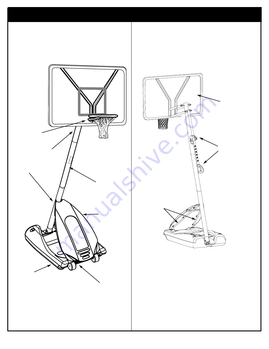
Get to know the basic parts of your basketball system.....
FRONT
TOP POLE
BACK
MIDDLE POLE
COVER
RIM
BOTTOM
POLE
STRUTS
ELEVATOR
ASSEMBLY
BACKBOARD
BASE
WHEEL
CARRIAGE
Страница 1: ...ard Scrap Tape Measure Step Ladder 8 ft 2 4 m Tape Garden Hose or Sand 360 lb 163 kg Hammer Wrenches Two 3 4 One 1 2 Two 9 16 or equivalent sockets One 1 2 Deep well socket with extension and socket w...
Страница 2: ...other sharp objects Punctures cause leakage and could cause system to tip over Keep organic material away from pole base Grass litter etc could cause corrosion and or deterioration Check pole system...
Страница 3: ...emble this system without following the instructions carefully Proper and complete assembly use and supervision is essential for proper operation and to reduce the risk of accident or injury A high pr...
Страница 4: ...4 P N 21147703 03 04 Get to know the basic parts of your basketball system FRONT TOP POLE BACK MIDDLE POLE FRONT COVER RIM BOTTOM POLE STRUTS ELEVATOR ASSEMBLY BACKBOARD BASE WHEEL CARRIAGE ASSEMBLY...
Страница 5: ...200874 Spacer Metal 1 53 Long 31 4 201124 Locknut 3 8 16 32 2 900867 Plate Triangle 33 2 904807 Elevator Tube Upper Short 34 2 900183 Elevator Tube Lower Long 35 2 204859 Cover Pin Slide 36 1 203124 T...
Страница 6: ...WS Item 14 2 Item 31 4 Item 55 1 Item 44 4 Item 11 21 Item 9 6 Item 50 6 Item 19 1 Item 29 4 Item 10 18 Item 43 2 Item 21 7 Item 22 2 Item 47 1 Item 13 2 HARDWARE IDENTIFIER NUTS WASHERS METAL SPACERS...
Страница 7: ...2 4 3 MOVING SYSTEM 1 Adjust basketball backboard height to lowest position 2 While holding pole rotate basketball system forward until wheels engage with ground 3 Move basketball system to desired l...
Страница 8: ...er l exc dent de peinture si n cessaire ANTES DE COMENZAR Para asegurar el ptimo rendimiento del sistema del respaldo en el juego se requiere un ajuste de tolerancia estrecha entre los componentes del...
Страница 9: ...scrap as shown until top pole no longer moves toward pole identification mark on middle pole middle pole IDENTIFICATION STICKER middle pole IDENTIFICATION STICKER 5 1 1 2 POLE IDENTIFICATION MARK THE...
Страница 10: ...ARE NOT SUPPLIED WITH THE HARDWARE 2 3 1 Bottom Pole IDENTIFICATION STICKER Bottom Pole IDENTIFICATION STICKER 5 1 1 2 Holes in top 1 and bottom pole 3 sections MUST align to correctly position eleva...
Страница 11: ...do not wear jewelry rings watches necklaces etc Objects may entangle in net Surface beneath the base must be smooth and free of gravel or other sharp objects Punctures cause leakage and could cause s...
Страница 12: ...s step 1 Assemble pole bracket 12 to pole 3 using bolt 13 and locknut 14 as shown 13 12 14 THE CUT CORNERS OF THE POLE BRACKET NEED TO FACE TOWARD THE BACK OF THE BASE AS SHOWN IMPORTANT IMPORTANT DO...
Страница 13: ...Repeat for opposite side 9 10 11 10 16 16 4 10 10 14 17 13 16 TWO PEOPLE REQUIRED FOR THIS PROCEDURE FAILURE TO FOLLOW THIS WARNING COULD RESULT IN SERIOUS INJURY AND OR PROPERTY DAMAGE WARNING IMPORT...
Страница 14: ...ls 6 to axle using pushnuts 7 Carefully tap pushnuts onto axle with hammer or mallet 4 6 6 7 7 5 Install wheel assembly to base 8 using bolts 9 washers 10 and nuts 11 as shown 10 9 11 10 8 SIDE OF WHE...
Страница 15: ...ON C ASSEMBLE THE ELEVATOR BACKBOARD This is what your system will look like when you ve finished this section 9 16 1 2 3 4 2 1 2 2 9 16 AND 2 3 4 Wrenches AND OR 2 Socket Wrenches and Sockets Item 31...
Страница 16: ...ket 18 with carriage bolts 22 as shown Tighten flange nuts 11 completely 1 28 11 11 18 22 22 2 Attach spacers 24 43 to pole mount bracket 28 with bolts 29 washers 44 and lock nuts 31 as shown IMPORTAN...
Страница 17: ...52 55 54 51 23 23 Assemble lanyard 26 to locking pin 27 as shown FIG A Attach covers 35 onto pole mount bracket 28 with carriage bolt 19 and nut 11 as shown 19 FIG A 26 27 Loop end of pin lanyard 26 o...
Страница 18: ...y as shown Lock pole assembly in place at the 10 3 05 m mark with pin 27 27 5 6 30 30 29 29 31 45 Assemble backboard brackets 45 using spacers 30 bolts 29 and nuts 31 as shown 31 IMPORTANT KEEP HARDWA...
Страница 19: ...50 and nut 21 as shown NOTE Rim mounting nuts and bolts supplied with rim hardware NOTE DO NOT use washers here on spring return style rims 34 34 46 49 48 Identify elevator tubes 33 34 59 41 40 33 Up...
Страница 20: ...h upper elevator tubes 33 to backboard support brackets 45 using spacers 46 49 bolt 50 and nut 21 as shown 50 49 49 21 46 33 33 33 49 45 49 21 46 50 33 IMPORTANT TIGHTEN ALL HARDWARE FROM STEP 6 8 AFT...
Страница 21: ...r tubes 33 to triangle plates 32 as shown Install handle assembly to lower elevator tubes 34 using bolt 50 spacers 20 and nut 21 as shown 50 34 34 20 20 Before going on to next step set adjustable sys...
Страница 22: ...51 11 Insert bolt 50 through left side upper elevator tube 33 then stretch spring 48 onto bolt 50 Insert bolt 50 through right side upper elevator tube 33 and secure with nut 21 50 48 USE EYE PROTECTI...
Страница 23: ...e 8 with water approx 40 gallons and snap fill caps 37 in place 56 36 37 8 37 TWO PEOPLE REQUIRED FOR THIS PROCEDURE FAILURE TO FOLLOW THIS WARNING COULD RESULT IN SERIOUS INJURY AND OR PROPERTY DAMAG...
Страница 24: ...ll front cover 38 by lining up stand offs along the tank struts Insert a tie strap 39 through the top two and bottom two stand offs Wrap tie straps around tank struts as shown and secure tightly Trim...
Страница 25: ...cated by arrows Push second arm back and into ram as shown Twist body of clip slightly again to spread arms of clip Clip arms must be flat and touching edge to edge as shown not overlapping A A B B C...
Страница 26: ...26 P N 21147703 03 04 Insert net into bottom of clip as shown SIDE VIEW Twist net until it snaps into position Net must be centered through clip NET NETCLIP SIDE VIEW NET NETCLIP 2 40 57 58...
Страница 27: ...asketball backboard height to lowest position 2 While holding pole rotate basketball system forward until wheels engage with ground 3 Move basketball system to desired location 4 Carefully rotate bask...
Страница 28: ...ON H HEIGHT ADJUSTMENT 1 A While holding handle remove pin 27 B Move elevator up or down to desired height C Replace pin 27 full length to lock system at desired height 27 A B C 51 DO NOT ALLOW CHILDR...