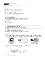
UVPPM Installation
1. Turn power off at the service panel.
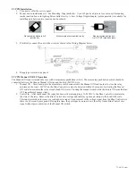
2. Mount unit in installation site. See Mounting Diagram below. Use 6x32 pan head screws to secure unit if mounting
inside junction box or in lighting fi xture ballast cavity. A Low Voltage Nipple Adapter (sold separately) is available for
installing unit between two junction box knockouts.
3. Electrically connect the unit to the circuit as shown in the Wiring Diagram below.
4. Reapply power at service panel.
UVPPM Manual ON/OFF Operation
The Manual ON input is intended for use with a momentary pushbutton switch. The momentary pushbutton switch should be
connected between the Orange Manual ON wire and the Red +24VDC wire.
1. Manual ON – Users must press the momentary switch connected to the Manual ON lead in order to close the relay
and turn on the load. +24VDC on the Blue Control wire must be detected within 30 seconds of activating the Manual
ON switch to maintain the relay closed (Load ON) status. Pressing the manual switch while the load is ON turns the load
OFF regardless of sensor status.
2. Control In – After the Manual ON input has been activated, ap12-24VDC to the Blue Control wire maintains
the state of the relay. Remove the Blue Control wire voltage and the relay opens and returns to the Load OFF state.
This input is intended for sensor or control device input. Upon removal of the voltage signal from the Blue Control wire,
there is a 30 second grace period. During this time, the power pack can re-activate the relay from a Blue Control wire
signal without prior activation of the Manual ON switch.
Mounts inside standard 4x4
junction box
Mounts outside junction box
via 1/2” EMT threaded nipple
Mounts inside fi xture ballast cavity
72-00370, revA


