background image


HUBBELL ELECTRICAL PRODUCTS 

A Division of HUBBELL INCORPORATED  (Delaware)


3940 Dr. Martin Luther King Drive 
St. Louis, Missouri  63113 USA 

INSTALLATION, OPERATION & 

MAINTENANCE DATA SHEET 

SERIES SJIC and SJICH JUNCTION BOXES 

Increased Safety Terminal Enclosures For Use In 

Zone Classified Hazardous Locations


P/N KIL00921446 FORM NO. K1446  R6/18  ECO-2-045-18   


Page 4 of 

10


Terminal  Block  Installation and  Wiring Instructions:   


a: 

  Attention to detail is highly recommended when installing and wiring the Terminal Blocks.   Proper installation is required to 

ensure the component Certification Ratings are not invalidated.  

b:  

Care should be taken not to damage or crack the DIN-Rail mounting clips when removing or installing polymeric terminal blocks.  

Damaged or loose-fitting  terminal blocks should be replaced before energizing the device.


c:

  Refer to each Terminal Block Manufacturer's  Installation Instructions for suitable wire types (ie: Solid, Stranded), proper wire 

stripping lengths, and terminal torques.  

OVERTIGHTENED  or 


LOOSE WIRE  TERMINALS  MAY  CAUSE   OVERHEATING,   

WHICH  CAN  RESULT  IN  AN  ELECTRIC  SHOCK  OR  EXPLOSION  HAZARD

d

  Care shall be taken to ensure proper separation of circuits (voltages), and spacings (creepage and clearance distances between 

live parts of opposite polarity, and between all live parts and dead metal) are maintained.  Refer to IEC/EN/UL/CSA 60079-7, Table 
2, for minimum creepage and clearance distances. 

e:

  Grounding connections are available at the din rail, earth continuity plate and internal- external ground stud.  Bonding 

connections are available on covers and boxes of all enclosures.  All exposed metal should be bonded per  local electrical codes. 


f:

  Wiring must be carried out in accordance with the relevant local and national electrical codes (ie: IEC/EN 60079-14, IEC/EN 

61241-0 and IEC/EN 61241-1. 

g:


All conductor insulation and terminal block service temperature ratings shall be suitable for (exceed)  the minimum 

ambient and maximum temperature (defer to T-Code) achieved in service.   All conductors shall be sized per the National 
or Local  Electrical  Codes for the max. continuous current or max. motor load of the installation. 

h:

  C

onductors at entry points may reach 73

o

C in a +55

o

C ambient, and may reach 108

o

C in a +90

o

C ambient  (See Note j 

below).    

i

:

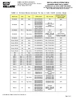
  Only the terminal blocks listed on Killark certificates  may be installed in the enclosures. See 

Table A

 below. 

j:

  No more than one conductor shall not be permitted in a wire terminal, unless the device has been evaluated specifially for  

multiconductor installation  (See Terminal Block Mfr's Installation Instructions).   Ferrules may be used if the Terminal Block has 
been approved for use with Solid Wires of equivalent diameter. 

k:

  When installing Terminal blocks,  the maximum voltage, current and dissipated power shown on the Junction Box nameplate 

must not be exceeded. 

l:

   When Weidmuller 

WDU 1.5 or WDU 2.5

 Series Terminal Blocks are installed, they are limited to a 

maximum current of 15A

j:

  When provided with a non-metallic enclosure (Series SJICN), these devices are limited to a maximum ambient temperature of 

+60C.


Conditions For Safe Use (IECEx/ATEX):   


WARNING: Enclosures that are powder coated have a potential electrostatic charging hazard. Wipe the enclosure down 
with a moist cloth before servicing. 
 
Conductors at entry points may reach 73

o

C in a +55

o

C ambient (metal or non-metallic enclosures), and may reach 108

o

in a +90

o

C ambient (metal enclosures only). 

 
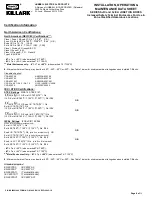
a:  The range of Killark polymeric enclosures (Series HKH) shall only be used in a service temperature range of -55

 O

C to +85

 O

C. 

 
b:  The range of metal enclosures shall only be used in a service temperature range of -55

 O

C to +135

 O

C. 

 
c:  When Junction Boxes are equipped by the manufacturer with wired terminals, a routine electric strength test is required per EN 
60079, Clause 6.1.  
 
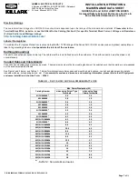
d:  The maximum dissipated power in watts for each model of junction box shall be calculated in accordance with EN 60079-7, 
Annex E, E.2, and shall not exceed the maximums given in Table 6 below.  


Содержание Killark SJIC

Страница 1: ... or death IMPORTANT Please read these instructions carefully before installing or maintaining this equipment Good electrical practices should be followed at all times and this data should be used as a guide only Technical information advice and recommendations contained in these documents is based upon information that Killark believes to be reliable All the information and advice contained in the...

Страница 2: ...ked ambient on the nameplate e A 1 4 20 UNC M6 ground earthing stud is supplied on all Series SJICH and SJICH stainless steel enclosures f To maintian proper IP ratings be sure to follow all mfr s mounting instructions when installing certified cable glands or conduit entries Warning Enclosures must be installed in the upright vertical position only Mounting the enclosures in a horizontal position...

Страница 3: ...ed etc per EN 60079 7 The operating service temperature of the enclosure is limited to the temperature of the gland fitting if less than the enclosure h Killark KDE series drain and breather may be installed The operating temperature of the enclosure is limited to the temperature of the drain and breathers if lower than the enclosure s Other drain and breathers may be installed the user is respons...

Страница 4: ...ll be suitable for exceed the minimum ambient and maximum temperature defer to T Code achieved in service All conductors shall be sized per the National or Local Electrical Codes for the max continuous current or max motor load of the installation h Conductors at entry points may reach 73o C in a 55o C ambient and may reach 108o C in a 90o C ambient See Note j below i Only the terminal blocks list...

Страница 5: ...52U IECEx FTZU 10 0011U 50o C Klemsan Elektrik PUK Screw FTZU 09ATEX0252U IECEx FTZU 10 0011U 50o C Klemsan Elektrik PYK Cage clamp FTZU 09ATEX0252U IECEx FTZU 10 0011U 50o C ABB ZS Screw LCIE 08ATEX0007U IECEx LCI 08 0031U 50o C ABB ZK Cage clamp LCIE 13ATEX3042U IECEx LCI 13 0025U 50o C WAGO 2001 Cage clamp PTB 05ATEX1094U IECEx PTB 11 0093U 50o C WAGO 2002 Cage clamp PTB 03ATEX1162U IECEx PTB 0...

Страница 6: ...9 7 ANSI ISA 60079 7 CSA 60079 31 ANSI ISA 60079 31 CSA No 94 1 94 2 No 14 UL50 UL50E UL508 CSA 60529 ANSI IEC 60529 IEC ATEX Certifications ATEX Ratings SIRA 14 ATEX 3157 0518 II 1 G Ex ia IIC T6 T5 T4 Ga II 2 D Ex tb IIIC T80o C T100o C T130o C Db IP66 OR 0518 II 2 G Ex eb IIC T6 T5 T4 Gb Ex ib IIC T6 T5 T4 Gb II 2 D Ex tb IIIC T80o C T100o C T130o C Db IP66 OR 0518 II 1 G Ex eb ib IIC T6 T5 T4 ...

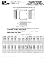
Страница 7: ...onnection must be made in all circumstances Conduit Hubs and Cable Glands Conduit hubs and cable gland sizes may be mixed The maximum number of hubs or cable glands must be selected such that the walls are not weakened nor the enclosure stability affected See Figure 1 and 2 below and Tables 1 7 below for metal enclosure dimensions and mounting hole locations conduit and gland mountnig details usea...

Страница 8: ... 75 121 2 47 63 3 13 79 3 13 79 1 19 30 SJIC 060404 6 152 4 102 4 102 2 00 51 6 75 171 2 47 63 5 13 130 3 13 79 3 19 81 SJIC 060604 6 152 6 152 4 102 4 00 102 6 75 171 2 47 63 5 13 130 5 13 130 3 19 81 SJIC 060606 6 152 6 152 6 152 4 00 102 6 75 171 4 47 114 5 13 130 5 13 130 3 19 81 SJIC 080606 8 203 6 152 6 152 4 00 102 8 75 222 4 47 114 7 13 181 7 13 181 5 19 132 SJIC 080804 8 203 8 203 4 102 6...

Страница 9: ... Blank Wall Area D Blank Wall Area E Blank Wall Area SJICH 060604 6 152 6 152 4 102 4 00 102 6 75 171 2 47 63 5 13 130 5 13 130 3 19 81 1 81 46 SJICH 060606 6 152 6 152 6 152 4 00 102 6 75 171 4 47 114 5 13 130 5 13 130 3 19 81 3 81 97 SJICH 080606 8 203 6 152 6 152 4 00 102 8 75 222 4 47 114 7 13 181 7 13 181 5 19 132 3 81 97 SJICH 080804 8 203 8 203 4 102 6 00 152 8 75 222 2 47 63 7 13 181 7 13 ...

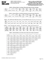
Страница 10: ...BLE 7 Minimum Distance From Center Line to Center Line of Conduit Cable Entries NPT Metric 4 3 1 2 3 M75 2 1 2 M63 2 M50 1 1 2 M40 1 1 4 M32 1 M25 3 4 M20 1 2 M16 IN mm 2 3 4 70 2 1 2 64 2 51 2 51 1 5 8 41 1 3 8 35 1 1 4 32 1 25 7 8 22 3 4 19 NPT Metric 4 3 1 2 3 M75 2 1 2 M63 2 M50 1 1 2 M40 1 1 4 M32 1 M25 3 4 M20 1 2 M16 IN mm 3 1 4 83 3 76 2 3 4 70 2 1 2 64 2 1 8 54 1 7 8 48 1 3 4 44 1 1 2 38 ...

Отзывы: