24
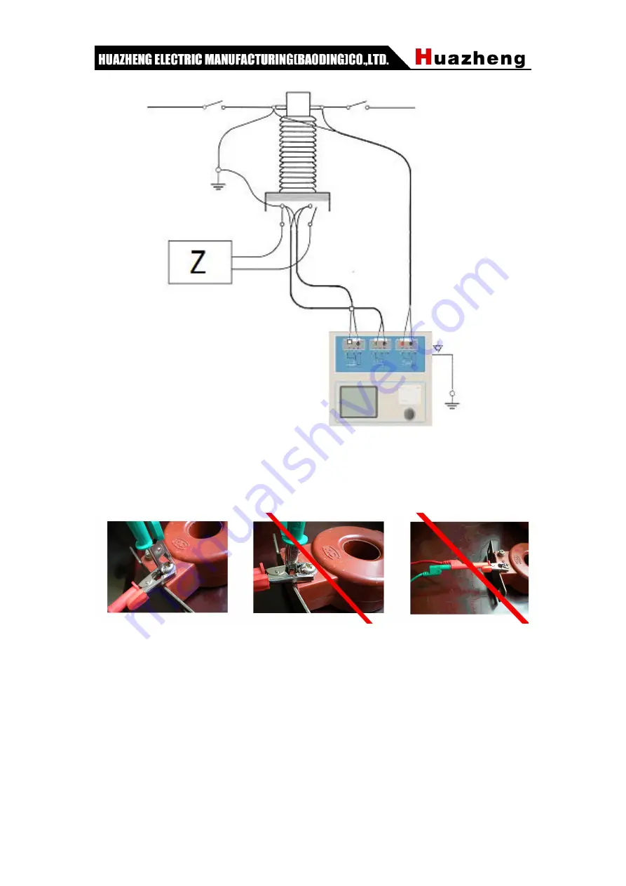
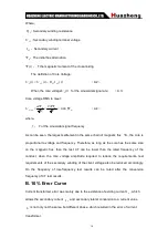
Figure E.4
Four-terminal method under test must pay attention to wiring terminal connection winding.
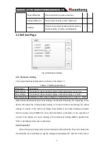
Figure E.5 the connection is correct, Figure E.6, 7 the connections are wrong.
Figure E.5
Figure E.6
Figure E.7
Страница 1: ...HZCT 100B CT PT Analyzer Huazheng Electric Manufacturing Baoding Co Ltd...
Страница 2: ...nt from the Manual In case of any changes we will inform you in the attached sheets Thanks for your understanding If anything is unclear please contact the After Sale Service Department in our company...
Страница 3: ...specifications of the product can be used Correct connection and disconnection When the test lead is connected to the charged terminal please don t connect or disconnect the test lead at will Earth th...
Страница 4: ...Avoid touching the exposed circuits or charged metal When the product is electrified never touch the exposed contacts or parts...
Страница 5: ...ate the product in a humid environment Never operate the product in an explosive environment Keep the surface of the product clean and dry Safety Terminology Warning Warning messages indicate the cond...
Страница 6: ...User Interface And Method Of Operation 3 2 1 Current Transformer 3 2 2 Voltage Transformer 11 2 3 Self test Page 14 2 5 Button Function 15 III Appendix 17 A Principle Of Low frequency Test 17 B 10 Er...
Страница 7: ...t but can also be used for the tests of various PTs including excitation characteristics of the electromagnetic unit ratio polarity secondary winding resistance ratio error and phase displacement Auto...
Страница 8: ...er output Green S1 black S2 terminal measure output voltage Red P1 black P2 terminal measure inductive voltage Keyboard Enter the value and operational command LCD screen GUI 1 3 Technical Parameter H...
Страница 9: ...onnection Used for selecting one or more experiment item including four options such as resistance excitation ratio burden etc According to transformer type four options can be combinated as shown in...
Страница 10: ...the table 2 1 to wiring For all the CT structures please refer to the description of appendix D for the actual connection mode Step 2 The other windings of the same CT should be opened CT s primary s...
Страница 11: ...ng PR PX TPS TPX and TPZ etc 4 Current temperature When measure the temperature of winding generally input the current room temperature for reference 5 Rated frequency 50Hz or 60Hz 6 Maximum measured...
Страница 12: ...primary current Used to calculate the ratio of actual current accurately rated burden Rated load of plate power factor for 0 8 or 1 power factor Rated accurate limit coefficient alf K The provisions o...
Страница 13: ...fault 500m s Choose C t1 O tfr C t2 O Cycle will be shown t2 Current time limit for the second time default 100m s Choose C t1 O tfr C t2 O Cycle will be shown tal2 Second the flow by maintaining accu...
Страница 14: ...limit voltage Ial correspondin g with Ual Note expressed the need for settings that do not need to set up a blank 2 1 3 Test Results The test result interface as shown in fig 2 4 Fig 2 4 The test resu...
Страница 15: ...tage and knee current unit V and A According to standard definition when knee voltage increase 10 knee current increase 50 Unsaturated inductance u L unit H The average inductance of linear section fo...
Страница 16: ...alcuated coefficient Rated knee potential Ek Ie correspondin g with Ek The actual excitation current corresponding with rated knee potential Rated voltage Ual The rated equivalent second limit voltage...
Страница 17: ...periment project description experiment item Description Connection diagram resistanc e excitatio n ratio burden Measure PT s secondary winding resistance Fig 2 5 must disconnection if measuring prima...
Страница 18: ...sh interface parameter Settings Switch cursor to where the parameter you want to set by turning the Rotating mouse 1 Serial number and resistance number Input letters and numbers directly 2 Rated seco...
Страница 19: ...nd experiment item the results will be also different The detailed as shown in Table 2 5 Table 2 5 PT test results description result description P M Resistanc e resistance 25 R unit resistance value...
Страница 20: ...ncy Installation of the output voltage or current frequency scope 0 50Hz After testing Current test set or test voltage set the test frequency the frequency of the device will output the corresponding...
Страница 21: ...2 5 Button Function 2 5 1 Button Function For Parameter Interface 1 Open A Report The interface of opening a report is shown in Fig 2 10 Choose to open a report the relative information will be displa...
Страница 22: ...urve Selecting the error curve the relationship curve of rated primary current multiple and maximum burden will be shown as fig 2 14 according to 10 or 5 error The x axis is rated primary current mult...
Страница 23: ...e Of Low frequency Test IEC60044 6 standard corresponding to the national standard GB16847 1977 claims CT test can be done in conditions lower in frequency than the rated and avoid secondary windings...
Страница 24: ...and frequency Therefore as long as the core has the same size on the magnetic flux then the test CT can be lower than the rated frequency of the conduct when the core voltage amplitude required to re...
Страница 25: ...efinite M as a multiple of the maximum short circuit current K for the current transformer ratio there are N N N M I I I K I K I I M 2 0 2 1 1 1 10 B 4 Where M I1 The largest one side short circuit cu...
Страница 26: ...areas 3 To ensure that all the CT terminal of the other transmission lines disconnect from all other windings open 4 2 5mm2 red and black line CT secondary side connected to the HZCT 100B Output K1 an...
Страница 27: ...ction transformer CT test conducted on the connection mode as shown in Figure D 2 Figure D 2 HZCT 100B in the triangle on the transformer connection when the connection mode test Figure D 2 HZCT 100B...
Страница 28: ...the HZCT 100B cannot obtain the correct result Figure D 3 HZCT 100B on the transformer bushing testing at the time of CT Connection 4 HZCT 100B in the GIS SF6 switch on the wiring of the CT test mode...
Страница 29: ...in V Vs so if the accurate measurement of impedance R can not simply replace the Vs with V Impedance R of the measuring circuit should be used Figure E 2 connection method measuring the voltage meter...
Страница 30: ...ure E 4 Four terminal method under test must pay attention to wiring terminal connection winding Figure E 5 the connection is correct Figure E 6 7 the connections are wrong Figure E 5 Figure E 6 Figur...
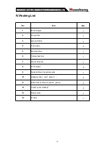
Страница 31: ...round lead 1 4 Fuse pipe 5 5 Red test line 1 6 Yellow test line 1 7 Green test line 1 8 Print paper 4 9 Special driver insurance tube 1 10 Alligator clips red 1 black 1 2 11 Small clip 2 black 1yellow...