background image

UPS5000-E-(600 kVA-800 kVA) 
User Manual 

3 Installation 


Issue 02 (2016-01-20) 

Huawei Proprietary and Confidential                                     

Copyright © Huawei Technologies Co., Ltd. 

56 


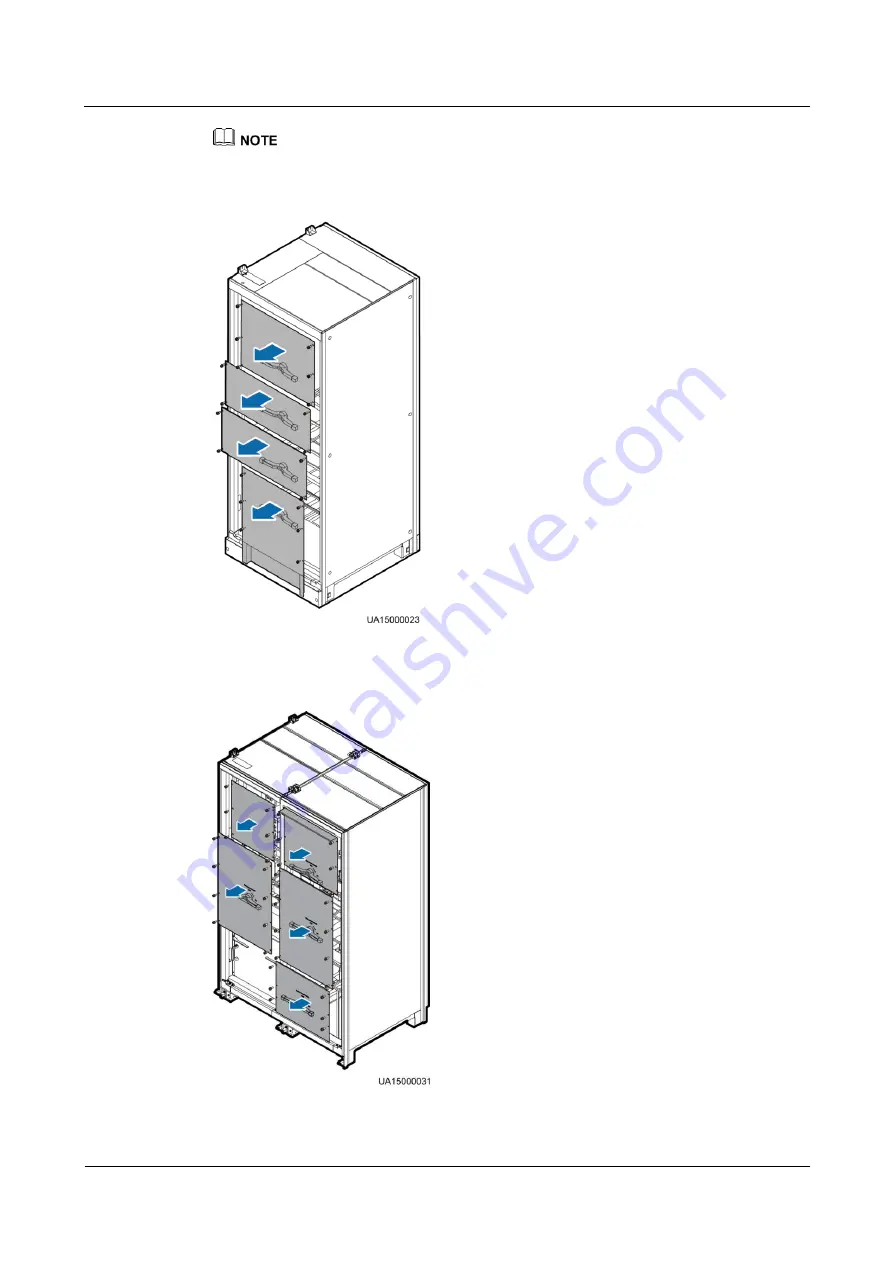
The power distribution covers can be removed from the bypass cabinet only when all switches are OFF. 

Figure 3-22


Removing power distribution covers from the 600 kVA UPS 


Figure 3-23


Removing power distribution covers from the 800 kVA UPS 


Содержание UPS5000-E-600K-FC

Страница 1: ...UPS5000 E 600 kVA 800 kVA User Manual Issue 02 Date 2016 01 20 HUAWEI TECHNOLOGIES CO LTD ...

Страница 2: ... Huawei and the customer All or part of the products services and features described in this document may not be within the purchase scope or the usage scope Unless otherwise specified in the contract all statements information and recommendations in this document are provided AS IS without warranties guarantees or representations of any kind either express or implied The information in this docum...

Страница 3: ... Hardware installation engineers Commissioning engineers Data configuration engineers Maintenance engineers Symbol Conventions The symbols that may be found in this document are defined as follows Symbol Description Indicates an imminently hazardous situation which if not avoided will result in death or serious injury Indicates a potentially hazardous situation which if not avoided could result in...

Страница 4: ...ractices and tips NOTE is used to address information not related to personal injury equipment damage and environment deterioration Change History Changes between document issues are cumulative The latest document issue contains all the changes made in earlier issues Issue 02 2016 01 20 Updated the maximum voltage and current which the monitoring interface card can support optimized the dual bus s...

Страница 5: ...ion 11 2 2 Working Principle 11 2 2 1 Conceptual Diagram 11 2 2 2 Working Modes 12 2 2 2 1 Normal Mode 12 2 2 2 2 Bypass Mode 13 2 2 2 3 Battery Mode 14 2 2 2 4 Maintenance Bypass Mode 15 2 2 2 5 ECO Mode 16 2 3 Overview 17 2 3 1 Appearance 17 2 3 2 Product Structure 19 2 4 Control Module 23 2 4 1 Overview 23 2 4 2 ECM 23 2 4 3 Dry Contact Card 24 2 4 4 Optional Backfeed Protection Card 26 2 4 5 O...

Страница 6: ...p Cable Routing 70 3 2 3 2 Bottom Cable Routing 77 3 2 4 Connecting Ground Cables 83 3 2 5 Connecting AC Input Power Cables 86 3 2 5 1 Single Mains 86 3 2 5 2 Dual Mains 88 3 2 6 Connecting AC Output Power Cables 94 3 2 7 Connecting Battery Cables 96 3 2 8 Remote EPO 99 3 2 9 Connecting Communications Cables 100 3 3 Parallel System Installation 102 3 3 1 Connecting Power Cables 102 3 3 2 Connectin...

Страница 7: ... Page 169 4 2 2 4 Comm Config Page 170 4 2 2 5 Control Page 170 4 2 3 Query Page 171 4 2 3 1 Historical Alarms Page 171 4 2 3 2 Logs Page 172 4 2 4 Config Page 172 4 2 5 Maint Page 175 5 Operations 178 5 1 Single UPS Operations 178 5 1 1 Powering On and Starting the UPS 178 5 1 2 Shutting Down and Powering Off the UPS 189 5 1 3 Starting the UPS in Battery Mode 192 5 1 4 Transferring to Bypass Mode...

Страница 8: ...ance 225 6 1 UPS Maintenance 225 6 2 Battery Maintenance 227 7 Troubleshooting 231 8 Technical Specifications 233 8 1 Physical Specifications 233 8 2 Environmental Specifications 233 8 3 Safety Regulations and EMC 234 8 4 Mains Input Electrical Specifications 234 8 5 Bypass Input Electrical Specifications 235 8 6 Battery Specifications 235 8 7 Output Electrical Specifications 235 8 8 System Electr...

Страница 9: ...d they must understand basic safety precautions to avoid hazards Follow the precautions and special safety instructions provided by Huawei when operating Huawei products Huawei will not be liable for any consequences that are caused by the violation of the general safety regulations and equipment design production and usage safety standards Declaration Huawei does not take responsibilities for the...

Страница 10: ...uipment Only trained and qualified personnel are allowed to remove safety facilities and inspect the equipment Only personnel certified or authorized by Huawei are allowed to replace or change the devices or components including software Operation personnel must report faults or errors that might cause serious safety issues to related owners This product should be installed and used by following t...

Страница 11: ...s If you use the UPS for life supporting medical apparatus and facilities such as lifts where adequate care has to be taken to ensure personal safety discuss with the manufacturer in advance about the applicability settings management and maintenance of the UPS which require special considerations during design Device Safety Before operation ensure that the device is firmly anchored to the floor o...

Страница 12: ...amp environment ensure that the device is dry When water is found in the rack or the rack is damp switch off the power supply immediately High Leakage Current Ground a device before powering it on Otherwise personal injury or device damage may occur If a high leakage current tag is attached to the panel of the device you must ground the protective ground terminal on the device enclosure before con...

Страница 13: ...that the circuit is connected to the UPS Disconnect the device from the UPS before performing operations on the circuit Electrostatic Discharge The static electricity generated by human bodies may damage the electrostatic sensitive components on boards for example the large scale integrated LSI circuits Human body movement friction between human bodies and clothes friction between shoes and floors...

Страница 14: ...m the following environments Places where the temperature and humidity are beyond the range of 0 40 C and 0 95 RH respectively Places in direct sunlight or near heat sources Places subject to vibrations or shocks Dusty places or places exposed to corrosive substances or salts Marine environments or outdoor land environments with simple shielding measures near pollution sources If a site is near a ...

Страница 15: ...ode metal parts and circuit boards and ultimately damage the circuit boards Short circuits caused by incorrect operations may cause serious injuries due to high power of batteries Do not reversely connect positive and negative battery terminals Use batteries of the specified type Otherwise the batteries may be damaged Check battery connections periodically to ensure that all screws are securely ti...

Страница 16: ...overturn batteries Switch off the power supply during installation and maintenance Short Circuit Battery short circuits may cause personal injury The high transient current generated by a short circuit may release a surge of power and cause a fire To avoid battery short circuits do not maintain batteries in use Harmful Gas Do not use unsealed lead acid batteries Lead acid batteries emit flammable ...

Страница 17: ...orb the leaking electrolyte Sodium bicarbonate baking soda NaHCO3 Sodium carbonate soda Na2CO3 When using substances to counteract and absorb electrolytes strictly follow the guidelines provided by the battery manufacturer If your body comes in contact with battery electrolyte wash with clean water immediately and seek medical advice if the situation is serious 1 5 Mechanical Safety Moving Sharp O...

Страница 18: ...that have been stored in a temperature lower than 0 C 32 F move the cables to an environment of the ambient temperature and store them at the ambient temperature for at least 24 hours Handle cables with caution especially at a low temperature Do not drop the cables directly from the vehicle As the insulation layer of a cable may age or be damaged at high temperatures ensure a sufficient distance b...

Страница 19: ... 40 kVA power modules It can expand up to 600 kVA and is compatible downwards to 40 kVA This document describes the 600 kVA UPS The UPS5000 E 800K SC FC uses 40 kVA power modules It can expand up to 800 kVA and is compatible downwards to 40 kVA This document describes the 800 kVA UPS 2 2 Working Principle 2 2 1 Conceptual Diagram The UPS5000 E is an online UPS with a modular design that facilitate...

Страница 20: ...nceptual diagram Figure 2 2 UPS conceptual diagram 2 2 2 Working Modes indicates an input mode indicates the energy flow direction 2 2 2 1 Normal Mode In normal mode the rectifier converts AC power into DC power Then the inverter converts DC power into high precision AC outputs The conversions protect loads from interference such as input harmonics glitches and voltage transients Figure 2 3 shows ...

Страница 21: ...de 2 2 2 2 Bypass Mode The UPS automatically transfers to bypass mode upon detecting power module overtemperature overload or other faults that may cause the inverter to shut down The bypass power supply is not protected by the UPS and therefore tends to be affected by mains outage and abnormal AC voltage or frequency Figure 2 4 shows the conceptual diagram of the UPS working in bypass mode ...

Страница 22: ...gies Co Ltd 14 Figure 2 4 UPS conceptual diagram in bypass mode 2 2 2 3 Battery Mode If the AC input voltage is abnormal the UPS transfers to battery mode The power module obtains power from batteries and then the inverter converts the power into AC outputs Figure 2 5 shows the conceptual diagram of the UPS working in battery mode ...

Страница 23: ... Figure 2 5 UPS conceptual diagram in battery mode 2 2 2 4 Maintenance Bypass Mode In maintenance bypass mode the current flows through maintenance bypass circuits instead of the power module or bypass module You can perform maintenance on the UPS in this mode Figure 2 6 shows the conceptual diagram of the UPS working in maintenance bypass mode ...

Страница 24: ...O mode when the bypass input voltage is within the ECO voltage range the static bypass switch turns on and the bypass supplies power manual startup is required to ensure that the inverter is in standby state and the power flow has reached the inverter When the bypass input voltage is out of the ECO voltage range the UPS transfers from bypass mode to normal mode In bypass mode or normal mode the re...

Страница 25: ...r Manual 2 Overview Issue 02 2016 01 20 Huawei Proprietary and Confidential Copyright Huawei Technologies Co Ltd 17 Figure 2 7 UPS conceptual diagram in ECO mode 2 3 Overview 2 3 1 Appearance Figure 2 8 and Figure 2 9 show the UPS ...

Страница 26: ...ual 2 Overview Issue 02 2016 01 20 Huawei Proprietary and Confidential Copyright Huawei Technologies Co Ltd 18 Figure 2 8 600 kVA UPS 1 Power cabinet 1 2 Power cabinet 2 3 Anchor baffle plates 4 Bypass cabinet 5 Monitor display unit MDU ...

Страница 27: ...wei Technologies Co Ltd 19 Figure 2 9 800 kVA UPS 1 Power cabinet 1 2 Power cabinet 2 3 Anchor baffle plates 4 Bypass cabinet 1 5 Bypass cabinet 2 6 Monitor display unit MDU 2 3 2 Product Structure Figure 2 10 Figure 2 11 Figure 2 12 and Figure 2 13 show the product structures Figures are UPSs with the front doors open ...

Страница 28: ...Huawei Proprietary and Confidential Copyright Huawei Technologies Co Ltd 20 Figure 2 10 Product structure UPS5000 E 600 kVA in standard configuration 1 Power modules 2 Control module 3 Optional card slot behind the filler panel 4 Maintenance bypass switch 5 Bypass module ...

Страница 29: ...dential Copyright Huawei Technologies Co Ltd 21 Figure 2 11 Product structure UPS5000 E 600 kVA in full configuration 1 Power modules 2 Control module 3 Optional card slot behind the filler panel 4 Mains input switch 5 Output switch 6 Maintenance bypass switch 7 Bypass input switch 8 Bypass module ...

Страница 30: ...cture UPS5000 E 800 kVA in standard configuration 1 Power modules 2 Control module 3 Optional card slot behind the filler panel 4 Maintenance bypass switch 5 Bypass module Figure 2 13 Product structure UPS5000 E 800 kVA in full configuration 1 Power modules 2 Control module 3 Optional card slot behind the filler panel 4 Mains input 5 Maintenance bypass 6 Output switch ...

Страница 31: ...d card into this subrack Figure 2 14 shows the signal panel on the control module Figure 2 14 Signal panel on the control module 1 Ground terminal 2 Parallel port 1 3 BSC port 1 4 ECM 1 ready switch 5 Indicators for ECM 1 6 Parallel port 2 7 BSC port 2 8 ECM 2 ready switch 9 Indicators for ECM 2 10 Dry contact card 11 Dry contacts 12 MDU port 13 RS485 port 14 Fast Ethernet FE port 15 COM2 port 16 ...

Страница 32: ...connect UPSs in parallel use a parallel cable to connect the parallel ports on the ECMs of the UPSs N UPSs require N parallel cables so that at least two parallel cables are connected to each UPS which improves reliability BSC The BSC port is used in a dual bus system to synchronize output frequencies and phases between UPS systems ensuring that two buses can switch with each other 2 4 3 Dry Conta...

Страница 33: ...h Connected battery switch ON Disconnected battery switch OFF Disconnected BCB_DRV Port for controlling the trip of the battery switch in the BCB box 0 V battery switch not tripped 12 V battery switch tripped 0 V BCB_0V Port for secondary side ground EPO_NO Emergency power off EPO port If the normally open NO port is connected to the EPO_12V port EPO is triggered Disconnected EPO_12V 12 V EPO_NC E...

Страница 34: ...e backfeed protection card triggers alarm signals or quickly disconnects the backfeed loop The backfeed protection card uses relay contact signals The signal ports support any power signals with a voltage of no more than 240 V AC and a current of less than 4 A For details see the UPS Backfeed Protection Card User Manual 2 4 5 Optional Dry Contact Extended Card The dry contact extended card provide...

Страница 35: ...m Set unused dry contact signals to the unused state on the LCD In a parallel system ensure that used dry contacts properly connect to each UPS Figure 2 17 shows the signal ports on the monitoring interface card Figure 2 17 Monitoring interface card Table 2 3 describes the ports on the monitoring interface card Table 2 3 Ports on the monitoring interface card Port Silk Screen Description DO_1 NO D...

Страница 36: ... indicates D G control which cannot be changed COM DB26 MDU Provides FE RS485 I2C and CAN signals Battery temperature sensor port B_TEMP Connects to an indoor battery temperature sensor Southbound communications port 1 COM1 Connects to an ambient temperature and humidity sensor over two wires Southbound communications port 2 COM2 Connects to a southbound device such as a BMU Network port FE Connec...

Страница 37: ...ages of common parallel systems the dual bus system also provides outstanding availability and eliminates bottleneck failures but the configuration of the dual bus system is complex A 1 1 parallel system is a typical configuration You can set the number of requisite UPSs and redundant ones on the LCD and WebUI 2 5 1 Single UPS The UPS5000 E uses a modular design It uses multiple power modules conn...

Страница 38: ...of two independent UPS systems Each of these UPS systems in turn consists of one or more UPSs connected in parallel The dual bus system is highly reliable and is suitable for loads with multiple input terminals You can install a static transfer switch STS to start the bus synchronization controller BSC while the STS is optional and the BSC is a standard configuration Of the two UPS systems one is ...

Страница 39: ... 0800DC V8 BXA001 Controls the connection between battery strings and the UPS and supports overload short circuit protection and remote trip control 800 kVA PDU8000 0630DC V8 BXA001 PDU8000 0800DC V8 BXA001 Battery bus bar BBB box 600 kVA PDU8000 1250DC V8 BGA001 PDU8000 2000DC V8 BGA001 Converges the energy of multiple battery strings 800 kVA PDU8000 2000DCV8 BGA001 Antiseismic kit N A Reinforces...

Страница 40: ...ges and temperatures and battery string charge discharge currents and communicates with the UPS over Modbus Battery grounding failure detector N A Detects current leakage and generates alarms When equipped with a remote trip switch the detector protects devices and prevents fire disasters Detects battery grounding failures and sends alarm signals when the ground leakage current exceeds the specifi...

Страница 41: ...ions 3 1 1 Site 3 1 1 1 UPS Weight and Size Ensure that the ground or installation support can bear the weight of the UPS batteries and battery racks The weight of batteries and battery racks depends on site requirements Table 3 1 lists UPS weight Table 3 1 UPS weight Model Capacity Weight UPS5000 E 600 kVA 1350 kg 800 kVA 1670 kg Figure 3 1 and Figure 3 2 show the installation dimensions ...

Страница 42: ...PS5000 E 600 kVA 800 kVA User Manual 3 Installation Issue 02 2016 01 20 Huawei Proprietary and Confidential Copyright Huawei Technologies Co Ltd 34 Figure 3 1 600 kVA UPS installation dimensions unit mm ...

Страница 43: ...ive materials Keep the UPS away from direct sunlight dust volatile gases corrosive materials and salty air Do not install the UPS in environments with conductive metal scraps in the air The optimal operating temperatures for valve regulated lead acid VRLA batteries are 20 30 C Operating temperatures higher than 30 C shorten the battery lifespan and operating temperatures lower than 20 C reduce the...

Страница 44: ...ential Copyright Huawei Technologies Co Ltd 36 Reserve a clearance of at least 500 mm at the rear of the cabinet If you need to perform operations at the rear keep a clearance of at least 800 mm Figure 3 3 and Figure 3 4 show installation clearances Figure 3 3 600 kVA UPS installation clearances unit mm ...

Страница 45: ...t Huawei Technologies Co Ltd 37 Figure 3 4 800 kVA UPS installation clearances unit mm 3 1 2 Tools Insulate installation tools to prevent electric shocks You need to prepare the tools and meters required for installation Table 3 2 Tools and meters Tools and Meters Pallet truck Manual pallet truck Ladder Rubber mallet ...

Страница 46: ...rs Crimping tools Wire stripper Hydraulic pliers Clamp meter Multimeter Cable tie Level Polyvinyl chloride PVC insulation tape Cotton cloth Label Electrician s knife Electrostatic discharge ESD gloves Protective gloves Insulated gloves Insulation protective shoes Torque screwdriver Insulated adjustable wrench Inner hexagon spanner Brush Flat head screwdriver 2 5 mm Phillips screwdriver M3 M4 M5 M6...

Страница 47: ...ion is not recommended If multiple UPSs are to be connected in parallel input and output power cables for each UPS should have the same length and specifications Table 3 3 lists the recommended cross sectional areas for power cables Table 3 3 Recommended cross sectional areas for power cables Item 600 kVA 800 kVA Mains input connector Mains input current A 1055 1407 Recommended cross sectional are...

Страница 48: ...5 52 or local regulations The currents listed in Table 3 3 are measured at a rated voltage of 380 V If the rated voltage is 400 V multiply the currents by 0 95 If the rated voltage is 415 V multiply the currents by 0 92 If primary loads are non linear loads increase the cross sectional areas of neutral wires 1 5 1 7 times When the mains input and bypass input share a power source configure both ty...

Страница 49: ...le 3 5 Upstream input circuit breaker configurations Upstream Input Circuit Breaker 600 kVA 800 kVA Upstream mains input switch 1250 A 3P 1600 A 3P Upstream bypass input switch 1000 A 3P 1250 A 3P Table 3 6 Recommended input front end and output back end circuit breakers UPS Capacity Component Specifications Manufacturer 600 kVA Mains input circuit breaker E1N1250 R1250 PR121 P LIS 3P ABB recommen...

Страница 50: ...fore moving it To prevent shocks or falls move the UPS gently After placing the UPS in the installation position unpack it and take care to prevent scratches Keep the UPS steady during unpacking If the UPS installation environment is in poor condition and the UPS will be stored for a long time after it is unpacked wrap the UPS with the original plastic coat to prevent dust The power cabinet and by...

Страница 51: ... Technologies Co Ltd 43 Figure 3 5 Pallet 1 Place for inserting the forks of an electric pallet truck 2 Place for inserting the forks of a manual pallet truck Step 3 Cut off and remove the binding tapes as shown in Figure 3 6 Figure 3 6 Removing binding tapes Step 4 Remove the packing materials and foam as shown in Figure 3 7 ...

Страница 52: ... Check that the UPS is intact 1 Visually inspect the UPS appearance for shipping damage If it is damaged notify the carrier immediately 2 Check that the fittings comply with the packing list Table 3 7 and Table 3 8 list the fittings If some fittings are missing or do not comply with the packing list record the information and contact your local Huawei office immediately Step 7 Remove the screws th...

Страница 53: ...ntext UPSs in standard configuration and full configuration have the same installation procedures and cable connection modes This section uses UPSs in full configuration as an example When you install the UPS and connect cables do not step on the front door baffle plate and the door support at the bottom of the cabinet to prevent paint flake off and deformation as shown in Figure 3 9 Otherwise the...

Страница 54: ...he Ground Determining the UPS Installation Position Ensure that the installation ground is flat The marking off template is delivered with the UPS and is placed at the top of the UPS Step 1 Determine the cabinet installation position on the ground according to cabinet mounting holes ground installation on the marking off template Figure 3 10 and Figure 3 11 show the marking off template Figure 3 1...

Страница 55: ...n Issue 02 2016 01 20 Huawei Proprietary and Confidential Copyright Huawei Technologies Co Ltd 47 Figure 3 10 600 kVA UPS marking off template Figure 3 11 800 kVA UPS marking off template Figure 3 12 Mounting hole dimensions for the 600 kVA UPS unit mm ...

Страница 56: ...nstalling expansion bolts and install expansion sleeves in the holes Figure 3 14 shows expansion bolt composition Figure 3 15 shows how to install an expansion bolt Figure 3 14 Expansion bolt composition 1 M12 bolt 2 Spring washer 3 Flat washer 4 Expansion sleeve Knock the expansion bolt into the hole until the expansion sleeve completely fits into the hole The expansion sleeve must be completely ...

Страница 57: ...ing washer and flat washer End Combining the Power Cabinet and Bypass Cabinet The power cabinet and bypass cabinet are separately delivered Before installing the UPS combine the power cabinet and bypass cabinet Before combining the cabinets check that fittings are complete Table 3 7 and Table 3 8 list the fittings Table 3 7 600 kVA UPS fittings Mounting Fittings Number of Fittings Screw Specificat...

Страница 58: ... UPS fittings Mounting Fittings Number of Fittings Screw Specificati ons Number of Bolts PCS Torque N m Remarks Bottom connecting plate 2 M12x25 8 26 The fittings are delivered with the UPS and are visible when you remove the packing material from the bypass cabinet The two soft connecting copper bars are numbered 52 Optional Eight L shaped connecting copper bars seven of which are numbered 50 and...

Страница 59: ...cificati ons Number of Bolts PCS Torque N m Remarks Middle connecting plate 2 M6x30 4 3 Installed on the cabinet before delivery Step 1 Optional Obtain eight L shaped connecting copper bars from the fittings package and install them in the 800 kVA power cabinet from inside to outside as shown in Figure 3 16 If the eight L shaped connecting copper bars have already been installed skip this step ...

Страница 60: ...e ground The power cabinet is on the left and the bypass cabinet is on the right as shown in Figure 2 8 and Figure 2 9 When you align the power cabinet with the bypass cabinet adjust the position of the bypass cabinet by using a pallet truck so that the front doors of the two cabinets are aligned with each other Step 3 Install the two bottom connecting plates on power cabinet 1 and its adjacent by...

Страница 61: ...awei Technologies Co Ltd 53 Figure 3 17 Installing bottom connecting plates Step 4 Install the two top connecting plates on power cabinet 1 and its adjacent bypass cabinet The method is the same for the 600 kVA UPS and 800 kVA UPS Figure 3 18 uses the 600 kVA UPS as an example Figure 3 18 Installing top connecting plates ...

Страница 62: ... secure the 800 kVA UPS by using M6x30 screws The method is the same for the 600 kVA UPS and 800 kVA UPS Figure 3 19 uses the 600 kVA UPS as an example After the power cabinet is aligned with the bypass cabinet secure the connecting plate between the two cabinets by using M6 screws to minimize the gap in between Figure 3 19 Installing connecting plates Step 6 Use M12x60 expansion bolts to secure t...

Страница 63: ...ogies Co Ltd 55 Figure 3 20 Tightening expansion bolts Step 7 Install the front rear left and right anchor baffle plates as shown in Figure 3 21 using the 600 kVA UPS as an example Figure 3 21 Installing front rear left and right anchor baffle plates Step 8 Remove the power distribution covers as shown in Figure 3 22 and Figure 3 23 ...

Страница 64: ... and Confidential Copyright Huawei Technologies Co Ltd 56 The power distribution covers can be removed from the bypass cabinet only when all switches are OFF Figure 3 22 Removing power distribution covers from the 600 kVA UPS Figure 3 23 Removing power distribution covers from the 800 kVA UPS ...

Страница 65: ...10 Remove the switch extension pole Figure 3 24 Removing the switch extension pole 800 kVA For an 800 kVA model the switch extension pole in the left bypass cabinet must be removed to facilitate cabinet combination The switch extension pole in the right bypass cabinet can be removed or reserved which has no impact For a 600 kVA model removing the switch extension poles or not does not affect cabin...

Страница 66: ... condition and reinstalled after cables are connected Keep the dowel leveled as shown in Figure 3 24 and Figure 3 25 Insert the switch extension pole until it is fully inserted place the spacer and tighten the slotted screw Step 11 Install soft connecting copper bars between power cabinet 1 and its adjacent bypass cabinet The following describes the methods for the 600 kVA UPS and 800 kVA UPS sepa...

Страница 67: ...ssue 02 2016 01 20 Huawei Proprietary and Confidential Copyright Huawei Technologies Co Ltd 59 Figure 3 26 Removing a battery copper bar assembly b Install soft copper bars numbered from 48 to 54 from inside outwards Figure 3 27 shows the soft copper bars ...

Страница 68: ...tary and Confidential Copyright Huawei Technologies Co Ltd 60 Figure 3 27 Installing soft copper bars numbered from 48 to 54 c Reinstall the battery copper bar assembly d Remove the filler panel from the power cabinet and install soft copper bars named 56 58 and 60 as shown in Figure 3 28 ...

Страница 69: ...ial Copyright Huawei Technologies Co Ltd 61 Figure 3 28 Installing soft copper bars numbered 56 58 and 60 800kVA UPS a Cut off the binding tapes between soft copper bar holes numbered 23 24 25 26 and 30 b Secure the soft copper bars numbered 23 24 25 26 and 30 by using M12x45 screws as shown in Figure 3 29 ...

Страница 70: ...al Copyright Huawei Technologies Co Ltd 62 Figure 3 29 Securing soft copper bars numbered c Remove the filler panel from the power cabinet and take out the two soft copper bars numbered 52 from the fitting bag Secure them separately to power cabinet 1 and its adjacent bypass cabinet as shown in Figure 3 30 ...

Страница 71: ...ologies Co Ltd 63 Figure 3 30 Installing soft copper bars numbered 52 Step 12 Insert the cable terminal on the bypass cabinet into the corresponding port on the system signal interface board in power cabinet 1 The system signal interface board is located at the rear of power cabinet 1 which can be seen if the rear panel is removed ...

Страница 72: ...fy that the cables are correctly connected and reinstall the rear panels The silk screens on the system signal interface board in power cabinet 1 are shown in Figure 3 31 The mapping between the cables in the bypass cabinet and the ports on the system signal interface board is listed in Table 3 9 Figure 3 32 and Figure 3 33 show cable connections for combined cabinets Figure 3 31 Silk screens on t...

Страница 73: ...able No Quantity CT cable W309_J26 J26 1 Switch cable In full configuration 600 kVA 04091624 06 800 kVA 04091625 06 In standard configuration SW1310 04091626 23 1 A standard model has only one switch cable maintenance bypass switch A full configuration model has three bypass switches main input switch maintenance bypass switch and bypass input switch The following figures use a full configuration ...

Страница 74: ...5000 E 600 kVA 800 kVA User Manual 3 Installation Issue 02 2016 01 20 Huawei Proprietary and Confidential Copyright Huawei Technologies Co Ltd 66 Figure 3 32 Cable connection for combined cabinets 600 kVA ...

Страница 75: ...eels should be purchased by the customer The recommended channel steel width is 50 mm or more Ensure that the spacing between external sides of a channel steel is 800 mm Secure channel steels to the ground by using expansion bolts Keep the channel steel surface flat Step 1 Determine the cabinet installation position on channel steels according to cabinet mounting holes channel steel installation o...

Страница 76: ...t Huawei Technologies Co Ltd 68 Figure 3 34 Dimensions of cabinet base mounting holes for the 600 kVA UPS unit mm 1 Channel steel mounting hole 2 Channel steel 3 Column 4 Base Figure 3 35 Dimensions of cabinet base mounting holes for the 800 kVA UPS unit mm 1 Channel steel mounting hole 2 Channel steel 3 Column 4 Base ...

Страница 77: ...the method of combining them on the ground For details see Combining the Power Cabinet and Bypass Cabinet in 3 2 1 1 Installing the UPS on the Ground End Securing the UPS Step 1 Use M12x45 comment bolts to secure the cabinet to the mounting holes in the channel steel and tighten the bolts Step 2 Install the front rear left and right anchor baffle plates as shown in Figure 3 21 End 3 2 2 Installing...

Страница 78: ...0 0630 1250 2000 DCV8 BGA001 BBB Box User Manual delivered with the BBB Box End 3 2 3 Routing Cables 3 2 3 1 Top Cable Routing Context Top cable routing is recommended Bottom cable routing is applicable only when a cable tray or support is used If an IP21 component is installed cables cannot be routed from the top of the cabinet If you choose to route cables through holes remove the power cable tr...

Страница 79: ...o outside to secure wires 1 Remove the power cable tray cover battery cable tray cover and signal cable tray cover from the top of the cabinet Use a hole saw to drill holes in the power cable tray cover attach grommet strips around the holes to protect cables and reinstall the power cable tray cover on the cabinet as shown in Figure 3 36 and Figure 3 37 The hole size and quantity are for reference...

Страница 80: ...opyright Huawei Technologies Co Ltd 72 Figure 3 37 Removing cable tray covers from the top of the 800 kVA UPS 1 Signal cable tray cover 2 Battery cable tray cover 3 Power cable tray cover 4 Spare power cable tray cover 2 Optional Remove the 10 screws that secure the beam as shown in Figure 3 38 and Figure 3 39 ...

Страница 81: ...UPS5000 E 600 kVA 800 kVA User Manual 3 Installation Issue 02 2016 01 20 Huawei Proprietary and Confidential Copyright Huawei Technologies Co Ltd 73 Figure 3 38 Removing the beam from the 600 kVA UPS ...

Страница 82: ... Proprietary and Confidential Copyright Huawei Technologies Co Ltd 74 Figure 3 39 Removing the beam from the 800 kVA UPS Store the removed screws and beam Reinstall them after connecting cables 3 Figure 3 40 and Figure 3 41 show the power cables routed from the top of the cabinet ...

Страница 83: ...wei Proprietary and Confidential Copyright Huawei Technologies Co Ltd 75 Figure 3 40 Routing power cables from the top of the cabinet and binding position covers removed of 600 kVA UPS 1 Battery cables 2 Bypass input power cables 3 Output power cables 4 Mains input power cables ...

Страница 84: ...es from the top of the cabinet and binding position covers removed of the 800 kVA UPS 1 Battery cables 2 Bypass input power cables 3 Output power cables 4 Mains input power cables Bind signal cables and power cables separately Step 3 Route signal cables Bind signal cables to the cabinet in the shortest route Figure 3 42 shows the signal cables routed from the top of the cabinet ...

Страница 85: ...from the bottom of the cabinet ensure sufficient space at the bottom of the cabinet If you choose to route cables through holes remove power cable tray covers and drill holes After you drill holes paste grommet strip to the hole edge to protect cables Reinstall the covers on the cabinet After routing cables use firestop putty to fill in the gap between the cables and the cabinet Procedure Step 1 O...

Страница 86: ...hten screws from inside to outside to secure wires 1 Remove the power cable tray cover and signal cable tray cover from the bottom of the cabinet Use a hole saw to drill holes in the power cable tray cover attach grommet strips around the holes to protect cables and reinstall the power cable tray cover on the cabinet as shown in Figure 3 43 and Figure 3 44 The hole size and quantity are for refere...

Страница 87: ...roprietary and Confidential Copyright Huawei Technologies Co Ltd 79 Figure 3 44 Removing cable tray covers from the bottom of the 800 kVA UPS 1 Signal cable tray cover 2 Power cable tray cover 2 Figure 3 45 and Figure 3 46 show the power cables routed from the bottom of the cabinet ...

Страница 88: ... 20 Huawei Proprietary and Confidential Copyright Huawei Technologies Co Ltd 80 Figure 3 45 Routing power cables from the bottom of the cabinet and binding position 600 kVA UPS 1 Battery cables 2 Mains input power cables 3 Output power cables 4 Bypass input power cables ...

Страница 89: ...3 46 Routing power cables from the bottom of the cabinet and binding position 800 kVA UPS 1 Battery cables 2 Mains input power cables 3 Output power cables 4 Bypass input power cables Step 3 Lay out signal cables Bind signal cables to the cabinet in the shortest route Figure 3 47 and Figure 3 48 show the signal cables routed from the bottom of the cabinet ...

Страница 90: ...E 600 kVA 800 kVA User Manual 3 Installation Issue 02 2016 01 20 Huawei Proprietary and Confidential Copyright Huawei Technologies Co Ltd 82 Figure 3 47 Routing signal cables from the bottom of the 600 kVA UPS ...

Страница 91: ...dential Copyright Huawei Technologies Co Ltd 83 Figure 3 48 Routing signal cables from the bottom of the 800 kVA UPS The number and colors of signal cables in Figure 3 47 and Figure 3 48 are for reference only End 3 2 4 Connecting Ground Cables Figure 3 49 and Figure 3 50 show the UPS wiring terminals ...

Страница 92: ...tion Issue 02 2016 01 20 Huawei Proprietary and Confidential Copyright Huawei Technologies Co Ltd 84 Figure 3 49 600 kVA UPS PDU 1 Mains input wiring terminals 2 Battery input wiring terminals 3 Output wiring terminals 4 Bypass input wiring terminals ...

Страница 93: ...isasters may occur Before cable connections ensure that all UPS input switches are OFF Paste warning labels to prevent operation on the switches Connect input power cables to the UPS and then to customer equipment The figure is for reference only For details about the recommended cross sectional area and number of ground cables refer to Table 3 3 and site requirements In the case of top cable rout...

Страница 94: ...er Cables 3 2 5 1 Single Mains This figure is for reference only For details about recommended cable specifications and numbers see Table 3 3 Select and install cables based on site requirements After connecting cables check that a certain clearance is reserved between the internal switch if any extension pole and power cables to avoid friction Connecting AC input power cables to mains input power...

Страница 95: ...UPS5000 E 600 kVA 800 kVA User Manual 3 Installation Issue 02 2016 01 20 Huawei Proprietary and Confidential Copyright Huawei Technologies Co Ltd 87 Figure 3 53 AC input power cables connection 600 kVA ...

Страница 96: ...dential Copyright Huawei Technologies Co Ltd 88 Figure 3 54 AC input power cables connection 800 kVA 3 2 5 2 Dual Mains Procedure Step 1 Remove the rear cover of the bypass cabinet as shown in Figure 3 55 It is recommended that you remove the side panel from the bypass cabinet before connecting cables ...

Страница 97: ...wei Proprietary and Confidential Copyright Huawei Technologies Co Ltd 89 Figure 3 55 Removing the rear cover Step 2 Remove the connecting copper bars between mains and bypass input terminals as shown in Figure 3 56 and Figure 3 57 Properly keep the removed copper bars and bolts ...

Страница 98: ...ies Co Ltd 90 Figure 3 56 Removing copper bars from the 600 kVA UPS Figure 3 57 Removing copper bars from the 800 kVA UPS Step 3 Connect mains input power cables to mains input terminals 1L1 1L2 and 1L3 respectively Connect the neutral wires of mains input power cables to input N wiring terminals as shown in Figure 3 58 and Figure 3 59 ...

Страница 99: ... E 600 kVA 800 kVA User Manual 3 Installation Issue 02 2016 01 20 Huawei Proprietary and Confidential Copyright Huawei Technologies Co Ltd 91 Figure 3 58 Connecting mains input power cables to the 600 kVA UPS ...

Страница 100: ... Copyright Huawei Technologies Co Ltd 92 Figure 3 59 Connecting mains input power cables to the 800 kVA UPS Step 4 Connect bypass input power cables to bypass input terminals 2L1 2L2 2L3 Connect the neutral wires of bypass input power cables to input N wiring terminals as shown in Figure 3 60 and Figure 3 61 ...

Страница 101: ...f the mains input and bypass input use different power sources connect four N wires to the 600 kVA UPS and six N wires to the 800 kVA UPS After connecting cables check that a certain clearance is reserved between the internal switch if any extension pole and power cables to avoid friction Figure 3 60 ConnectingAC input power cables to the 600 kVA UPS ...

Страница 102: ...right Huawei Technologies Co Ltd 94 Figure 3 61 ConnectingAC input power cables to the 800 kVA UPS Step 5 Reinstall the rear cover in the cabinet End 3 2 6 Connecting AC Output Power Cables After you connect output power cables if loads are not ready to be powered insulate the end of the system output power cable ...

Страница 103: ...s sectional area and number of AC output power cables refer to Table 3 3 and site requirements After connecting cables check that a certain clearance is reserved between the internal switch if any extension pole and power cables to avoid friction Connect the output power cables to output wiring terminals N U V and W as shown in Figure 3 62 and Figure 3 63 Figure 3 62 ConnectingAC output power cabl...

Страница 104: ...igure 3 63 ConnectingAC output power cables to the 800 kVA UPS 3 2 7 Connecting Battery Cables The battery voltage may result in serious injury Observe safety precautions when connecting cables Ensure that cables are correctly connected between battery strings and the battery switch and between the battery switch and the UPS Avoid inverse connections ...

Страница 105: ...hnologies Co Ltd 97 The figure is for reference only For details about the recommended cross sectional area and number of battery cables refer to Table 3 3 and site requirements Connect battery cables to battery wiring terminals N and as shown in Figure 3 64 and Figure 3 65 Figure 3 64 Connecting battery cables to the 600 kVA UPS ...

Страница 106: ...Co Ltd 98 Figure 3 65 Connecting battery cables to the 800 kVA UPS Route a neutral wire from the middle of the positive and negative battery strings Take a battery string consisting of 40 batteries as an example Figure 3 66 shows a neutral wire routed from the middle of positive and negative battery strings each consisting of 20 batteries ...

Страница 107: ...provide the EPO switch or cable Prepare them by yourself The recommended cable is 22 AWG Equip the EPO switch with a protective cover to prevent misoperations and cover the cable with protective tubing Triggering EPO will shut down the rectifier inverter charger and static bypass but does not disconnect the UPS mains input To power off the UPS completely turn off the front end input switch when yo...

Страница 108: ...ch is in the NC state remove the jumper between EPO_NC and EPO_12V before connection When you turn off the EPO switch EPO is triggered When the EPO switch is in the NO state ensure that the jumper is connected between EPO_NC and EPO_12V When you turn on the EPO switch EPO is triggered 3 2 9 Connecting Communications Cables Procedure Step 1 Connect the external network management device to the RS48...

Страница 109: ...GND 7 N A 8 N A If cables are prepared onsite follow the three methods below Connect pin 1 and pin 2 Pin 1 connects to RS485 and pin 2 connects to RS485 Connect pin 4 and pin 5 Pin 4 connects to RS485 and pin 5 connects to RS485 Connect pins 1 2 4 and 5 Twist cables to pin 1 and pin 4 into one cable and then connect it to RS485 Twist cables to pin 2 and pin 5 into one cable and then connect it to ...

Страница 110: ...nect power cables for each UPS For details see section 3 2 5 Connecting AC Input Power Cables and 3 2 6 Connecting AC Output Power Cables Step 3 Connect battery power cables of each UPS For details see section 3 2 7 Connecting Battery Cables Step 4 Choose a parallel mode and connect cables to the parallel system based on site requirements Figure 3 70 Figure 3 71 and Figure 3 72 show the typical co...

Страница 111: ... clearly and simply show cable connections this document uses the number of oblique lines to indicate the number of power cables of the same type Connect power cables according to port silk screen Figure 3 71 Connecting cables to a 1 1 parallel system 600 kVA 1 Mains input power cables 2 Bypass input power cables 3 Battery cables 4 Output power cables ...

Страница 112: ...ower cables 2 Bypass input power cables 3 Battery cables 4 Output power cables Figure 3 73 Figure 3 74 and Figure 3 75 show the conceptual diagram and cable connections for a bus system consisting of two UPS systems respectively The length and specifications of power cables on each UPS must be the same to achieve current equalization in bypass mode The power cables include bypass input power cable...

Страница 113: ...UPS5000 E 600 kVA 800 kVA User Manual 3 Installation Issue 02 2016 01 20 Huawei Proprietary and Confidential Copyright Huawei Technologies Co Ltd 105 Figure 3 73 Conceptual diagram of a dual bus system ...

Страница 114: ...on Issue 02 2016 01 20 Huawei Proprietary and Confidential Copyright Huawei Technologies Co Ltd 106 Figure 3 74 Connecting cables to a dual bus system 600 kVA 1 Mains input power cables 2 Bypass input power cables 3 Battery cables 4 Output power cables ...

Страница 115: ...ng cables to a dual bus system 800 kVA 1 Mains input power cables 2 Bypass input power cables 3 Battery cables 4 Output power cables End 3 3 2 Connecting Signal Cables Connecting Signal Cables to a Parallel System Connect the parallel ports on the UPSs over parallel cables to create a loop Figure 3 76 and Figure 3 77 show the wiring principle for an N X parallel system ...

Страница 116: ... Issue 02 2016 01 20 Huawei Proprietary and Confidential Copyright Huawei Technologies Co Ltd 108 Figure 3 76 N X parallel system topology Figure 3 77 shows only the CM which stands for the UPS Figure 3 77 Signal cable connections of N X parallel system ...

Страница 117: ...re added for the master and slave systems Figure 3 78 shows cable connections in a dual bus system consisting of two master systems in parallel Figure 3 78 Connecting signal cables to a dual bus system Connecting Other Signal Cables Connect signal cables to each UPS in the parallel system by referring to 2 4 Control Module 3 4 Installing Optional Components 3 4 1 Installing Antiseismic Kits ...

Страница 118: ... Install antiseismic kits only when the cabinet is floor mounted Step 1 Mark mounting holes on the ground according to the marking off template as shown in Figure 3 10 and Figure 3 11 Figure 3 79 and Figure 3 80 show the dimensions of antiseismic kit mounting holes Figure 3 79 Dimensions of antiseismic kit mounting holes for the 600 kVA UPS unit mm ...

Страница 119: ... 3 80 Dimensions of antiseismic kit mounting holes for the 800 kVA UPS unit mm Step 2 Drill holes for installing expansion bolts and install expansion sleeve by referring to section 3 2 1 1 Installing the UPS on the Ground Step 3 Open the front door and remove support baffle plates on the front of the cabinet as shown in Figure 3 81 Remove the rear covers ...

Страница 120: ...and Confidential Copyright Huawei Technologies Co Ltd 112 Figure 3 81 Removing support baffle plates Step 4 Use M6 screws to secure the antiseismic kits to the front and rear of the cabinet to a torque of 3 N m Using the front of the cabinet as an example the procedure is shown in Figure 3 82 ...

Страница 121: ...d 113 Figure 3 82 Securing the antiseismic kits to the cabinet Step 5 Adjust the cabinet to ensure that the expansion bolts holes align with the beneath half holes Step 6 Use M12x60 expansion bolts to firmly lock the front and rear antiseismic kits to the ground Using the front of the cabinet as an example the procedure is shown in Figure 3 83 ...

Страница 122: ...es and rear covers in the cabinet Step 8 Install the front and rear anchor baffle plates and left and right anchor baffle plates as shown in Figure 3 21 End 3 4 2 Installing an IP21 Component Context If the IP21 component is installed you cannot route cables at the top of the cabinet Procedure Step 1 Install leveling feet at the bottom of the IP21 component with two long feet on the front and two ...

Страница 123: ...d 115 Refer to the front and back silk screens on the surface of the IP21 component Figure 3 84 Installing leveling feet Step 2 Install the IP21 component at the top of the UPS cabinet by using M12 screws as shown in Figure 3 85 and Figure 3 86 Figure 3 85 Installing an IP21 component 600 kVA Figure 3 86 Installing an IP21 component 800 kVA End ...

Страница 124: ...midity Sensor See the UPS Ambient Temperature and Humidity Sensor User Manual Figure 3 87 shows the position of an ambient temperature and humidity sensor in the UPS Figure 3 87 Connecting a UPS to an ambient temperature and humidity sensor 3 4 4 Installing a BMU Procedure Step 1 Install a BMU For details see the UPS Battery Monitor Unit User Manual Figure 3 88 shows the BMU position in the UPS ...

Страница 125: ... Co Ltd 117 Figure 3 88 Connecting a BMU to the UPS End 3 4 5 Installing a Battery Grounding Failure Detector Procedure Step 1 Install a battery grounding failure detector For details see the UPS Battery Grounding Failure Detector User Manual Figure 3 89 and Figure 3 90 show the positions of battery grounding failure detectors in the UPSs ...

Страница 126: ...anual 3 Installation Issue 02 2016 01 20 Huawei Proprietary and Confidential Copyright Huawei Technologies Co Ltd 118 Figure 3 89 Position of a battery grounding failure detector in the 600 kVA UPS 1 Battery grounding failure detector ...

Страница 127: ...ure detector End 3 5 Installation Verification Table 3 11 lists check items Check items 10 and 11 listed in Table 3 11 carefully If the check results of these two items do not meet the acceptance criteria the UPS may be damaged Table 3 11 Installation checklist No Item Acceptance Criteria 01 Consistency between system configurations and delivery configurations The system configurations including m...

Страница 128: ...m ground bar which must be less than 1 ohm 08 Distances between cable ties Distances recommended 30 cm between cable ties are the same and no burr exists 09 Cable connections Cables are properly connected according to wiring diagrams 10 Live wire and neutral wire connections Input and output live wires and neutral wires are correctly connected Mains input terminals 1L1 1L2 1L3 and N bypass input t...

Страница 129: ... 02 2016 01 20 Huawei Proprietary and Confidential Copyright Huawei Technologies Co Ltd 121 After routing cables and checking cable connections use firestop putty to fill in the gap between the cables and the cabinets and reinstall the covers for the cabinets ...

Страница 130: ...f the cabinet The MDU allows you to control the UPS operation set parameters and view running status and alarms The MDU provides a status indicator and an LCD touchscreen as shown in Figure 4 1 Figure 4 1 MDU 1 Status indicator 2 LCD touchscreen Touch the LCD screen firmly because it is an industrial resistive touchscreen It is recommended that you use your fingernails for accurate selection and q...

Страница 131: ... Table 4 1 describes the status indicator Table 4 1 Status indicator Status Color Meaning On Red A critical alarm has been generated and the buzzer sounds continuously Yellow A minor alarm has been generated and the buzzer buzzes at 2 Hz Green The UPS is running properly Off N A The MDU is powered off 4 1 2 LCD Menu 4 1 2 1 Menu Hierarchy Figure 4 3 shows the LCD menu hierarchy ...

Страница 132: ...faces displayed in this document use the 600 kVA UPS as an example and correspond to the monitoring software version V100R001C10SPC009 and are for reference only The Settings Wizard screen is displayed when you start the UPS for the first time or when you restart the UPS after restoring factory settings as shown in Figure 4 4 You can set Language Time Network Param and System Param on the Settings...

Страница 133: ...ary and Confidential Copyright Huawei Technologies Co Ltd 125 Figure 4 4 Settings Wizard 4 1 2 3 Main Menu The LCD screen is divided into three parts status bar alarm bar and information area Figure 4 5 shows the default main screen Table 4 2 describes functions of all domains on the screen ...

Страница 134: ...status and buzzer status 2 Alarm bar Displays active alarms in a scrolling list and the number of active alarms based on severity Tap the alarm icon area to open the active alarm page 3 Informatio n area Displays the power flow as well as the key information such as load and battery information Tap the Bypass Mains Battery and Load icons to view details Table 4 3 describes the functions of common ...

Страница 135: ... Screen On the main screen tap System Info The System Info screen is displayed as shown in Figure 4 6 Figure 4 6 System Info screen For details about the menus on the System Info screen see appendix A 1 Menus on the LCD 4 1 3 1 Cabinet Data Screen On the System Info screen tap the UPS picture On the Cabinet Data screen select a module to view its running data points to a selected module as shown i...

Страница 136: ...ntial Copyright Huawei Technologies Co Ltd 128 Figure 4 7 Cabinet 1 Data screen Figure 4 8 Cabinet 2 Data screen 4 1 3 2 Runn Info Screen On the System Info screen tap to access the Runn Info screen On this screen you can query AC Output UPS Load Mains Input and Bypass Input See Figure 4 9 and Figure 4 10 ...

Страница 137: ... Manual 4 User Interface Issue 02 2016 01 20 Huawei Proprietary and Confidential Copyright Huawei Technologies Co Ltd 129 Figure 4 9 Runn Info screen 1 Figure 4 10 Runn Info screen 2 AC Output Figure 4 11 shows the AC Output screen ...

Страница 138: ...cy Hz AC output phase voltage AC output line voltage AC output phase current AC output frequency Power factor Proportion of output active power to output apparent power UPS Load Figure 4 12 shows the UPS Load screen Figure 4 12 UPS Load screen Active power kW Output active power of each phase on the UPS Apparent power kVA Output apparent power of each phase on the UPS Reactive power kVAR Output re...

Страница 139: ...actor Proportion of the peak value of load current to the valid value Mains Input Figure 4 13 shows the Mains Input screen Figure 4 13 Mains Input screen Phase voltage V Line voltage V Phase current A Frequency Hz Mains input phase voltage Mains input line voltage Mains input phase current Mains input frequency Power factor Proportion of the mains input active power to the mains input apparent pow...

Страница 140: ...input phase voltage Bypass input line voltage Bypass input phase current Bypass input frequency Power factor Proportion of the bypass input active power to the bypass input apparent power Battery Status Figure 4 15 shows the Battery Status screen Figure 4 15 Battery Status screen Battery Status The value can be Not connected Not chg or dis Hibernating Float charging Equalized charging or dischargi...

Страница 141: ...alled NA is displayed Backup time min Battery backup time estimated at the current load Remaining cap Remaining battery capacity Total Runtime Figure 4 16 shows the Total Runtime screen Figure 4 16 Total Runtime screen Bypass runtime h Time for which the UPS runs in bypass mode Inv runtime h Time for which the UPS runs in inverter mode The value takes an integer For example If the value is less th...

Страница 142: ...ed Ambient humid Humidity measured by the ambient temperature and humidity sensor Install the sensor If the sensor is not installed NA is displayed 4 1 3 3 Alarms Screen On the System Info screen tap to enter the Alarms screen On the Alarms screen you can view Active Alarms and Historical Alarms Buzzer Off and Clear Faults as shown in Figure 4 18 Figure 4 18 Alarms screen Active Alarms Figure 4 19...

Страница 143: ...e ID Location Generated and Cleared is displayed on this screen Figure 4 20 Historical Alarms screen Buzzer Off Two buzzer menus are available that is Buzzer On and Buzzer Off If the buzzer is muted Buzzer On is displayed on the operation screen If the buzzer is enabled Buzzer Off is displayed on the operation screen Figure 4 21 shows the Buzzer Off screen If you enable the buzzer the buzzer buzze...

Страница 144: ... have not logged in a login screen is displayed Enter a user name and password and tap Figure 4 22 Clear Faults screen Table 4 4 lists the default user names and preset passwords and describes the permission of the default users If you enter incorrect passwords for three consecutive times you will be locked out for 5 minutes 4 1 3 4 Settings Screen On the System Info screen click If you have not l...

Страница 145: ...e login screen enter a preset user name and password and click to log in The Settings screen is displayed as shown in Figure 4 24 and Figure 4 25 Table 4 4 lists the default user names and preset passwords and describes the permission of the default users If you enter incorrect passwords for three consecutive times you will be locked out for 5 minutes Figure 4 24 Settings screen 1 ...

Страница 146: ...right Huawei Technologies Co Ltd 138 Figure 4 25 Settings screen 2 Basic Settings Set the date and time correctly Incorrect time display in running and alarm information would lead to analysis errors during maintenance or repair Set basic parameters as shown in Figure 4 26 and Figure 4 27 Figure 4 26 Basic screen 1 ...

Страница 147: ... 139 Figure 4 27 Basic screen 2 Language Twelve languages including English Chinese and Italian are supported The default language is English Password The preset password is 000001 You can change the password Communications Settings Set communications parameters as shown in Figure 4 28 Figure 4 29 and Figure 4 30 Figure 4 28 Communication screen 1 ...

Страница 148: ...omputer through an LAN switch or router with the DHCP function the IP address can be allocated manually or automatically Manual Check that their IP addresses are two different values on the same network segment Automatic The MDU automatically searches for available IP addresses in the connected network Ensure that the MDU and PC are on the same network segment You can set IP address allocation to ...

Страница 149: ...e that the address that you set on the LCD is the same as that set for the DIP switch Otherwise communication fails BMUs BMUs can be cascaded A maximum of 12 BMUs can be cascaded BMU start address Set the BMU start address through the DIP switch on the BMU to 112 Ensure that the address that you set on the LCD is the same as that set for the DIP switch Otherwise communication cannot be implemented...

Страница 150: ...ult lower limit of bypass voltage is 20 If Output voltage level is 415 V the default upper limit of bypass voltage is 10 and the default lower limit of bypass voltage is 20 The parameter is configurable after the inverter shuts down Output frequency Hz Set the system output frequency level The value can be 50 Hz default or 60 Hz Battery capacity Ah Set the battery string capacity The value range i...

Страница 151: ...Settings Set System capacity and Power module capacity according to specifications Incorrect settings may cause an overload alarm which affects normal UPS running Set advanced parameters such as System capacity and Power module capacity as shown in Figure 4 32 Figure 4 33 Figure 4 34 and Figure 4 35 Figure 4 32 Advanced Param screen 1 Figure 4 33 Advanced Param screen 2 ...

Страница 152: ...iplied by the number of requisite power modules The Module quantity mismatch alarm will be generated if the setting is incorrect Power module capacity kVA Rated power module capacity Requisite modules Match the system capacity Redundant modules Set in accordance with loading capacity and redundant requirements Working mode The value can be Normal mode default Converter mode Self load mode or ECO B...

Страница 153: ...oon as the mains resumes If EOD restart is disabled clear the alarm manually or enable the function to restart the UPS EOD restart delay min If EOD restart is set to Enable the UPS starts working after EOD restart delay when the mains recovers from an EOD power failure The value range is 1 1440 min and the default value is 10 min Inverter async alarm Specifies whether the Inverter async alarm is d...

Страница 154: ...ance the work with the D G The D G power limiting value range is 0 5000 kVA and the default value is 800 kVA for the UPS5000 E 600 kVA and 1000 kVA for the UPS5000 E 800 kVA The D G charger power ratio value range is 0 100 and the default value is 0 Intra rack power module start delay s and Inter rack power module start delay s The two parameters enable the UPS to control the interval that each ra...

Страница 155: ...tage and the bypass voltage This facilitates uninterruptible transfer from normal mode to bypass mode The voltage adjustment range is 5 The default value is 220 0 when the voltage is 380 V 230 0 when 400 V 240 0 when 415 V Outp transf interrupt time Hz s The value range is 0 1 2 0 Hz s and the default value is 0 6 Hz s This parameter can be adjusted based on site requirements If Output freq track ...

Страница 156: ...ge must be greater than the ECO frequency range The value range is 0 5 Hz to 6 Hz and the default value is 2 Hz Maximum bypass voltage Upper threshold for the bypass voltage When the difference between the bypass voltage and the rated voltage exceeds this value the system determines that the bypass voltage is abnormal and that the bypass is unavailable When the voltage level is 380 V the value ran...

Страница 157: ...may lead to a data backup fault Retain default settings for Chg cur limiting coef and Cell float voltage Only professional maintenance personnel are allowed to change the settings When you set parameters ensure the following Chg cur limiting coef Transfer to equalized charging cur Coef Dis cur 0 1C EOD Dis cur 0 3C EOD Dis cur 0 5C EOD Dis cur 1 0C EOD Battery type must meet the actual situation C...

Страница 158: ...ser Manual 4 User Interface Issue 02 2016 01 20 Huawei Proprietary and Confidential Copyright Huawei Technologies Co Ltd 150 Figure 4 40 Battery Param screen 2 Figure 4 41 Battery Param screen 3 Figure 4 42 Battery Param screen 4 ...

Страница 159: ...ery equalized voltage The value can be 2 30 2 40 V cell 2 35 V cell by default The value is configurable in any mode Transfer to equalized charging cur coef C10 The battery enters equalized charge state when the battery current exceeds this parameter value The value range is 0 02 0 08 and the default value is 0 05 Automatic equalized charging When the value is Enable the UPS automatically changes ...

Страница 160: ... charging current limit decreases to 0 03 CA Battery charging stops if a battery overtemperature protection alarm when the temperature reaches the high temperature threshold plus 3 C is generated Backup time warning and Remain cap warning When the first two parameters are set to Enable an alarm is generated when the backup time or remaining capacity is less than the alarm threshold Dis cur 0 1C EO...

Страница 161: ...d all the dry contacts that are not used to prevent false alarms encloses a unit and encloses silk screen Specify dry contact settings on the following cards Dry contact card MUE05A provides dry contact signals for the battery grounding failure detector D G BCB box and PDCs Backfeed protection board MUE06A provides backfeed protection signals You need only to enable or disable this board Monitorin...

Страница 162: ...A User Manual 4 User Interface Issue 02 2016 01 20 Huawei Proprietary and Confidential Copyright Huawei Technologies Co Ltd 154 Figure 4 45 Contacts screen 2 Figure 4 46 Dry Contacts screen 3 Figure 4 47 Dry Contacts screen 4 ...

Страница 163: ...User Manual 4 User Interface Issue 02 2016 01 20 Huawei Proprietary and Confidential Copyright Huawei Technologies Co Ltd 155 Figure 4 48 Dry Contacts screen 5 Figure 4 49 Dry Contacts screen 6 Figure 4 50 Dry Contacts screen 7 ...

Страница 164: ...er to determine whether the port is used to detect the status of the PDU bypass input switch or system maintenance switch SPD SYSOUT Switch If the SPD SYSOUT switch is set to Enable the port has dry contact signal access How a user uses the port depends on the status of the SPD SYSOUT switch SPD SYSOUT switch function If the SPD SYSOUT switch is set to Enable this parameter is displayed on the scr...

Страница 165: ...nds to signal of the output dry contact DO_4 on the MUS05A MUE07A DO_1 Corresponds to signal of the output dry contact DO_1 on the MUE07A MUE07A DO_2 Corresponds to signal of the output dry contact DO_2 on the MUE07A MUE07A DO_3 Corresponds to signal of the output dry contact DO_3 on the MUE07A MUE07A DO_4 Corresponds to signal of the output dry contact DO_4 on the MUE07A MUE07A DO_5 Corresponds t...

Страница 166: ...r Intelligent power mode is applicable when a D G is configured which enables D G power supply when an outage occurs For details about the installation and configurations contact Huawei technical support ATS Works with the intelligent power device D G startup batt volt V cell Works with the intelligent power device The value range is 1 80 2 00 V cell and the default value is 1 80 V cell 4 1 3 5 Ma...

Страница 167: ...isplayed as shown in Figure 4 53 You can perform Battery Maint USB Operations Inv ON Inv OFF ECM Switchover and Screen Calib on the Maintenance screen You can also perform Paral Inv ON and Paral Inv OFF for parallel systems as shown in Figure 4 54 Figure 4 53 Maintenance Screen single UPS Figure 4 54 Maintenance Screen parallel system Battery Maint Menu ...

Страница 168: ...ery maintenance includes Forced Equalized Charging Shallow Dis Test and Capacity Test The next maintenance time displayed on the screen reminds you of the upcoming time to check batteries Figure 4 55 shows the Battery Maint screen Figure 4 55 Battery Maint screen Forced Equalized Charging Perform equalized charging on batteries forcibly Shallow Dis Test Discharge partial capacities of batteries Ca...

Страница 169: ...hnologies Co Ltd 161 Figure 4 56 USB Operations screen 1 Figure 4 57 USB Operations screen 2 Inv ON and Inv OFF Menus You can start and shut down the inverter using the LCD Before the inverter starts the system asks for confirmation to prevent misoperation Figure 4 58 shows the Inv ON screen and Figure 4 59 shows the Inv OFF screen ...

Страница 170: ...FF screen Inv ON The Inv ON screen allows you to start the inverter manually Inv OFF The Inv OFF screen allows you to shut down the inverter manually ECM Switchover Menu Only professional personnel are allowed to use this button This menu allows you to perform active standby switchover on the UPS When you need to maintain an ECM and it is working perform active standby switchover on the ECM as ...

Страница 171: ...low or red indicator is on or the green indicator is blinking before you maintain it Figure 4 60 ECM switchover Screen Calib Menu You can calibrate the screen as shown in Figure 4 61 Figure 4 61 Screen Calib screen 4 1 3 6 About Screen On the System Info screen tap About On the About screen you can view the UPS model manufacturer monitoring version and power version as shown in Figure 4 62 To view...

Страница 172: ...s input bypass input load and battery information Figure 4 63 System Status screen For details about the menus on the System Status screen see appendix A 1 Menus on the LCD 4 1 5 Common Functions Screen On the main screen choose Common Functions The Common Functions screen is displayed as shown in Figure 4 64 and Figure 4 65 The Common Functions screen allows you to query the information about the...

Страница 173: ...creen 1 Figure 4 65 Common Functions screen 2 For details about the menus on the Common Functions screen see appendix A 1 Menus on the LCD 4 2 WebUI 4 2 1 Login Procedure Step 1 Open the browser Internet Explorer 8 as an example and choose Tools Internet Options Step 2 On the Advanced tab page ensure that Use TLS 1 0 and Use TLS 1 1 are selected and click OK as shown in Figure 4 66 ...

Страница 174: ...ge version V100R001C10SPC700 or later the software package version also requires the selection of Use TLS 1 1 in addition to the default Internet Explorer settings In this case ensure that Use TLS 1 0 and Use TLS 1 1 are selected Figure 4 66 Settings in the Internet Options dialog box Step 3 Enter https UPS IP address in the address box of Internet Explorer select a language set User name and Pass...

Страница 175: ...e information and system maintenance upgrade calibration and variables commissioning operator common user 000001 Changeme Only browses the system running information exports system information historical alarms logs e labels and fault data starts shuts down the inverter rectify faults and controls the buzzer browser browser 000001 N A Only browses the system running information If you enter incorr...

Страница 176: ...ea Function 1 Running status area Displays the power flow and UPS running information 2 Menu bar Displays active alarms and real time data sets parameters sets communications information and provides control commands The Active Alarms page is displayed by default 3 Information area Displays system monitoring information 4 2 2 1 Active Alarms Page You can view active alarms on the Active Alarms pag...

Страница 177: ... You can view the real time system running data on the Real time Data page as shown in Figure 4 69 Figure 4 69 Real time Data page 4 2 2 3 Param Settings Page On the Param Settings page you can set basic parameters advanced parameters input parameters output parameters bypass parameters battery parameters and dry contacts The settings are the same as those on the LCD in 4 1 3 4 Settings Screen See...

Страница 178: ...2 4 Comm Config Page You can set communications information on the Comm Config page The settings are the same as those on the LCD in 4 1 3 4 Settings Screen See Figure 4 71 Figure 4 71 Comm Config page 4 2 2 5 Control Page On the Control page you can control the system as shown in Figure 4 72 For parallel systems you can also perform Paral Inv ON and Paral Inv OFF as shown in Figure 4 73 ...

Страница 179: ...2 Control page single UPS Figure 4 73 Control page parallel system For details about the menus on the Monitoring page see A 2 Menus on the WebUI 4 2 3 Query Page 4 2 3 1 Historical Alarms Page On the homepage click the Query tab On the Historical Alarms page you can query historical alarms based on severity generation time and clear time as shown in Figure 4 74 ...

Страница 180: ...page you can set Logs to Historical logs Cap test logs or Common test logs and query or export logs as shown in Figure 4 75 You can export historical logs but cannot query them Figure 4 75 Logs Page For details about the menus on the Query page see A 2 Menus on the WebUI 4 2 4 Config Page On the homepage click Config On the Config page you can set the user and site information as shown in Figure 4...

Страница 181: ... Manual 4 User Interface Issue 02 2016 01 20 Huawei Proprietary and Confidential Copyright Huawei Technologies Co Ltd 173 Figure 4 76 User Mgmt page On the User Mgmt page you can add modify or delete users and change user passwords ...

Страница 182: ...onfigured with NMS software If SNMP Trap is incorrectly set or not set system information will be lost or not reported in time The certificate is used for Secure Sockets Layer SSL encryption protection for WebUI login You need to apply to a third party institution for the certificate Configuration Management is used to upload and export configuration parameters in the monitoring system Multi brand...

Страница 183: ... details about the menus on the Config page see appendix A 2 Menus on the WebUI 4 2 5 Maint Page On the homepage click the Maint tab The Maint page provides the Calib Commissioning Var Upgrade and Download tabs The maintenance operations cover the Bypass Module and ECM as shown in Figure 4 78 Figure 4 79 Figure 4 80 and Figure 4 81 Figure 4 78 Calib page ...

Страница 184: ...00 E 600 kVA 800 kVA User Manual 4 User Interface Issue 02 2016 01 20 Huawei Proprietary and Confidential Copyright Huawei Technologies Co Ltd 176 Figure 4 79 Commissioning Var page Figure 4 80 Upgrade page ...

Страница 185: ...r Manual 4 User Interface Issue 02 2016 01 20 Huawei Proprietary and Confidential Copyright Huawei Technologies Co Ltd 177 Figure 4 81 Download page For details about the menus on the Maint page see appendix A 2 Menus on the WebUI ...

Страница 186: ...erations 5 1 Single UPS Operations 5 1 1 Powering On and Starting the UPS Prerequisites Measure the main and bypass input voltage and frequency of the UPS bypass cabinet or measure the voltage and frequency delivered by the external input power distribution cabinet to the UPS The voltage range is 138 485 V AC and the frequency range is 40 70 Hz Context ...

Страница 187: ...t the UPS has passed all check items described in section 3 5 Installation Verification Before you power on the UPS check that all external and internal switches are OFF except that the ready switches for the power module and bypass module are in locked state Figure 5 1 shows the bypass module ready switch on the 600 kVA UPS Figure 5 2 shows the bypass module ready switch on the 800 kVA UPS Figure...

Страница 188: ...figuration To power on a UPS in full configuration configured with an internal mains input switch internal bypass input switch internal output switch and internal maintenance bypass switch perform the following operations a Turn on the external bypass and mains input switches b Turn on the internal bypass input switch c Turn on the internal output switch d Turn on the internal mains input switch e...

Страница 189: ...owing steps If the UPS is starting for the first time set the language date and time network parameters and system parameters on the Settings Wizard screen If this is not the first startup retain the previous settings After you specify the settings the Bypass mode and No battery alarms are displayed on the LCD The main buttons on the Settings Wizard screen are described as follows Tap Previous to ...

Страница 190: ...Figure 5 6 Network Param screen After you set network parameters connect the UPS to the network over a network cable which enables you to remotely manage the UPS If you do not need remote management retain the default network parameter settings 4 On the System Param screen select Single default value or Parallel as shown in Figure 5 7 Set the voltage level output frequency battery capacity and the...

Страница 191: ...fter confirmation Output voltage level refers to the line voltage level Set it based on the site requirements Set Output frequency correctly otherwise loads may not work properly Figure 5 7 System Param screen 1 Battery parameter settings have great impact on battery maintenance battery lifespan and UPS discharge time When you set battery parameters note the following ...

Страница 192: ...nnected in series to form a battery string and two of such battery strings connected in parallel and then to the UPS set Number of cells to 192 192 x 1 and Battery capacity to 600 Ah 300 Ah 300 Ah It affects the charge voltage and discharge time An incorrect setting will cause a high or low charge voltage which greatly shortens the battery lifespan In addition the UPS may shut down before the batt...

Страница 193: ...e 4 4 lists the default user names and preset passwords and describes the permission of the default users If you enter incorrect passwords for three consecutive times you will be locked out for 5 minutes c In the displayed dialog box tap Yes to start the inverter as shown in Figure 5 10 Figure 5 10 Starting the inverter You can also tap System Info Maintenance and start the inverter on the Mainten...

Страница 194: ...s case ensure that Use SSL 3 0 and Use TLS 1 0 are selected In monitoring and power version V100R001C10SPC008 software package version V100R001C10SPC700 or later the software package version also requires the selection of Use TLS 1 1 in addition to the default Internet Explorer settings In this case ensure that Use TLS 1 0 and Use TLS 1 1 are selected Figure 5 11 Settings in the Internet Options d...

Страница 195: ...command when it cannot be started the startup command will be kept for 1 minute If the startup command is not cleared within 1 minute for example other faults occur on the module or you perform shutdown or rectify faults and the module can be started the module responds to the startup command Step 6 Ensure that the UPS transfers to normal mode View the system running diagram to check that the Bypa...

Страница 196: ... V the number of cells is the same as the number of batteries Use a multimeter to check that the sum of the absolute voltages of positive and negative battery strings are greater than a certain value 1 9 x Number of cells to ensure that the battery strings are connected properly Number of cells indicates the number of 2 V cells connected to the UPS Number of cells affects the charge voltage and di...

Страница 197: ... 1200 Ah Step 8 After checking that the battery strings are properly connected close the battery circuit breaker if there are multiple battery strings close the circuit breaker for each battery string and then the general circuit breaker between battery strings and the UPS After you turn on the battery string input switch the No batteries alarm disappears on the LCD while batteries are in the char...

Страница 198: ... the login screen displayed Table 4 4 lists the default user names and preset passwords and describes the permission of the default users If you enter incorrect passwords for three consecutive times you will be locked out for 5 minutes c In the displayed dialog box tap Yes to shut down the inverter as shown in Figure 5 16 Figure 5 16 Inv OFF screen You can also tap System Info Maintenance and shut...

Страница 199: ...ed dialog box click OK to shut down the inverter as shown in Figure 5 17 Figure 5 17 Shutting down the inverter Step 2 After the inverter shuts down if the bypass is normal the UPS transfers to bypass mode if the bypass is abnormal the UPS supplies no power and the loads shut down as shown in Figure 5 18 and Figure 5 19 Figure 5 18 Normal bypass After you shut down the inverter the Bypass mode ala...

Страница 200: ...output switch and internal maintenance bypass switch perform the following operations a Turn off the UPS internal mains and bypass input switches b Turn off the UPS internal output switch c Turn off the external mains and bypass input switches d Open the input surge protection circuit breaker if any on the input PDC To power off a UPS in standard configuration configured only with an internal main...

Страница 201: ...aker If there are multiple battery strings close the circuit breaker for each battery string and then the general circuit breaker between battery strings and the UPS Step 3 Measure the UPS battery string voltages in the battery input route by using a multimeter If the sum of the absolute voltages of positive and negative battery strings are greater than a certain value 1 9 x Number of cells the ba...

Страница 202: ...ttery cold start End 5 1 4 Transferring to Bypass Mode Before you shut down the inverter ensure that the bypass is normal If the bypass is abnormal after you shut down the inverter the UPS supplies no power and the loads shut down Perform Step 1 in section 5 1 2 Shutting Down and Powering Off the UPS to shut down the inverter over the LCD or WebUI After you shut down the inverter the UPS transfers...

Страница 203: ...UPS and the parallel system support the ECO mode for higher efficiency To avoid frequent transfer between ECO mode and normal mode do not set the ECO mode when the bypass input is unstable or is sensitive to load changes ECO mode is not recommended when the load is less than 10 Before transferring the UPS to ECO mode ensure that the bypass module works properly Procedure Step 1 Manually shut down ...

Страница 204: ...g ECO mode Step 4 Manually start the inverter After the inverter starts the UPS still works in bypass mode and the inverter is standby Figure 5 24 shows the power flow displayed on the System Status screen If the bypass is abnormal the inverter supplies power immediately If the inverter is not started the UPS may be disconnected Figure 5 24 System Status screen End ...

Страница 205: ...ain screen of the LCD tap System Info Tap The Maintenance screen is displayed Step 2 Optional If you have not logged in enter a user name and a password and then tap Table 4 4 lists the default user names and preset passwords and describes the permission of the default users If you enter incorrect passwords for three consecutive times you will be locked out for 5 minutes Step 3 On the Maintenance ...

Страница 206: ...rcurrent alarm The UPS generates an alarm You tap Stop on the right of Forced Equalized Charging End 5 1 6 2 Shallow Discharge Test Context Before a shallow discharge test ensure that The UPS works in normal mode with a load ratio change rate less than 10 The UPS has generated no battery overtemperature overvoltage or overcurrent alarm No generator is connected to the UPS The mains batteries charg...

Страница 207: ... right of Shallow Dis Test to start a shallow discharge test as shown in Figure 5 27 Figure 5 27 Starting a shallow discharge test When the battery test is complete the test data is used as common test data You need to record the data obtained from the latest five tests The shallow discharge test stops in any of the following cases The battery discharge capacity reaches the specified value 10 50 2...

Страница 208: ...lt user names and preset passwords and describes the permission of the default users If you enter incorrect passwords for three consecutive times you will be locked out for 5 minutes Step 3 On the Maintenance screen tap Battery Maint as shown in Figure 5 25 Step 4 Tap Start on the right of Capacity Test to start a capacity test as shown in Figure 5 28 Figure 5 28 Starting a capacity test The capac...

Страница 209: ...ance screen is displayed Step 3 Optional If you have not logged in enter a user name and a password and then tap Table 4 4 lists the default user names and preset passwords and describes the permission of the default users If you enter incorrect passwords for three consecutive times you will be locked out for 5 minutes Step 4 Choose USB Operations Download Logs and select a log download path as sh...

Страница 210: ... Ltd 202 Figure 5 30 Confirming the path End Download over the WebUI Procedure Step 1 Log in to the WebUI Step 2 Choose Query Logs select Cap test logs or Common test logs from the Log drop down list box then click Export to export logs as shown in Figure 5 31 and Figure 5 32 Figure 5 31 Capacity test logs Figure 5 32 Common test logs End ...

Страница 211: ...e maintenance bypass If the mains is abnormal the loads may power off Procedure Step 1 Transfer the UPS to bypass mode by following the steps in section 5 1 4 Transferring to Bypass Mode Step 2 Turn on the maintenance bypass switch If the maintenance bypass switch is locked unlock it first Figure 5 33 shows a locked maintenance bypass switch After you turn on the maintenance bypass switch the UPS ...

Страница 212: ...dard configuration The preceding figure uses the 600 kVA UPS in standard configuration as an example The operations are the same for the 600 kVA UPS in full configuration and the 800 kVA UPS Exercise force when turning on or off the bypass maintenance switch Figure 5 35 Maint breaker closed alarm After the UPS transfers to maintenance bypass mode the Maint breaker closed and Bypass mode alarms are...

Страница 213: ... off the maintenance bypass switch Turn the maintenance bypass switch from the ON position to the OFF position as shown in Figure 5 36 The Maint breaker closed alarm disappears from the alarm list Check whether the UPS works in bypass mode by viewing the system running status diagram on the LCD or WebUI Figure 5 36 Turning off the maintenance bypass switch 600 kVA UPS in standard configuration The...

Страница 214: ... on the EPO switch the UPS supplies no power and the loads shut down In maintenance bypass mode the UPS still supplies power after you turn on the EPO switch Press the EPO switch connected to the dry contact card on the UPS or remove the 4 pin terminal from the EPO port on the dry contact card as shown in Figure 5 37 The UPS transfers to the EPO state An alarm is generated on the MDU and WebUI as ...

Страница 215: ... supplied alarms are displayed on the LCD 5 1 10 Clearing the EPO State Procedure Step 1 Turn off the EPO switch to clear the EPO state Step 2 Clear the EPO alarm LCD On the main screen tap System Info and On the Alarms screen tap Clear Faults If you have not logged in enter a user name and password and tap on the login screen displayed In the displayed dialog box tap Yes to clear the EPO alarm as...

Страница 216: ...ologies Co Ltd 208 Figure 5 40 Alarms screen Figure 5 41 Clearing the alarm WebUI In a web browser enter the https UPS IP address On the login page select a display language enter a user name and password and click Login On the homepage choose Monitoring Control and click Clear Fault to clear the EPO alarm as shown in Figure 5 42 ...

Страница 217: ...al the UPS transfers to the bypass mode LCD On the main screen tap System Info and On the Alarms screen tap Active Alarms to check that the EPO alarm disappears from the alarm list as shown in Figure 5 43 Figure 5 43 Active Alarms screen WebUI In a web browser enter the https UPS IP address On the login page select a display language enter a user name and password and click Login On the homepage c...

Страница 218: ...arms page Step 4 Start the inverter by following Step 4 to Step 5 in section 5 1 1 Powering On and Starting the UPS End 5 2 Setting Hibernation Mode Context When the load power is small and stable the inverters in some power modules shut down so that these power modules enter hibernation state and the other power modules bear all the load power This improves the system efficiency reduces power con...

Страница 219: ...ibernation mode check that the number of redundant power modules and racks are appropriate If the number is insufficient the UPS may not enter hibernation mode You can set hibernation mode on the LCD or WebUI 5 2 1 LCD Procedure Step 1 On the main screen tap System Info and The Settings screen is displayed If you have not logged in enter a user name and password and tap on the login screen display...

Страница 220: ...k that the load power is stable that is no transient surge results in overload which may cause the UPS to transfer to bypass mode and tap Yes Step 5 Set Module cycle hiber period d to an integer ranging from 1 to 100 The default value is 30 End 5 2 2 WebUI Procedure Step 1 On the login page enter a user name and password and click Login Step 2 Choose Monitoring Param Settings Advanced Parameters a...

Страница 221: ... Intelligent Power Mode Context Before you connect the D G to a UPS system check that the system is a single UPS system and that the system is working in non inverter mode and has connected to batteries When the UPS is working the D G starts if a mains outage occurs and the battery voltage reaches the specified threshold You can set intelligent power mode on the LCD or WebUI 5 3 1 LCD Procedure St...

Страница 222: ...er function is available only if the value is Enable The default value is Disable ATS The value can be Connected or Not connected When the value is Connected the UPS works in the ATS scenario when the value is Not connected the UPS works in the reused scenario The default value is Connected This parameter is available only after you set Intelligent power to Enable D G startup batt volt V cell The ...

Страница 223: ...d 215 Step 4 After you set Intelligent power to Enable the system automatically changes some parameters associated with intelligent power Figure 5 51 to Figure 5 56 show the changed parameters on the LCD Figure 5 51 Parameters associated with intelligent power on the LCD 1 Figure 5 52 Parameters associated with intelligent power on the LCD 2 ...

Страница 224: ...Proprietary and Confidential Copyright Huawei Technologies Co Ltd 216 Figure 5 53 Parameters associated with intelligent power on the LCD 3 Figure 5 54 Parameters associated with intelligent power on the LCD 4 Figure 5 55 Parameters associated with intelligent power on the LCD 5 ...

Страница 225: ...aptability Strong N A Output freq track rate Hz s 0 6 N A D G connection GEN Enable N A MUS05A DO_4 D G control N A ATS Connected N A D G startup batt volt V cell 1 80 N A D G power limiting kVA N A Indicates the actual D G power Set it as required D G charger power ratio N A Indicates the percentage of the battery power provided by the charger Set it as required In battery mode not battery test s...

Страница 226: ...ep 1 On the login page enter a user name and password and click Login Step 2 Choose Monitoring Param Settings Under Intelligent Power Settings set Intelligent power to Enable as shown in Figure 5 57 Figure 5 57 Intelligent power parameters on the WebUI Intelligent power The value can be Enable or Disable The intelligent power function is available only if the value is Enable The default value is D...

Страница 227: ...power to Enable the system automatically changes some parameters associated with intelligent power Figure 5 58 to Figure 5 63 show the changed parameters on the WebUI Figure 5 58 Parameters associated with intelligent power on the WebUI 1 Figure 5 59 Parameters associated with intelligent power on the WebUI 2 Figure 5 60 Parameters associated with intelligent power on the WebUI 3 ...

Страница 228: ...ght Huawei Technologies Co Ltd 220 Figure 5 61 Parameters associated with intelligent power on the WebUI 4 Figure 5 62 Parameters associated with intelligent power on the WebUI 5 Figure 5 63 Parameters associated with intelligent power on the WebUI 6 Table 5 3 lists the parameters associated with intelligent power ...

Страница 229: ...t volt or Low battery voltage the UPS triggers D G startup signals In normal mode or bypass mode if the mains is normal the mains supplies power for 1 minute and the D G runs for 15 minutes the UPS triggers D G shutdown signals If the battery voltage is greater than D G startup batt volt the UPS exits intelligent power mode and triggers D G shutdown signals If the battery voltage is less than D G ...

Страница 230: ...toring interface card to the startup shutdown control port on the D G The initial status of the DO_4 dry contact is normally open NO When it is closed the D G starts Figure 5 65 shows the signal cable connection between the UPS and the D G in reused scenarios Figure 5 65 Connecting signal cables in the reused scenario 5 3 4 ATS Scenario The D G and mains connect to the UPS over an ATS The MDU obta...

Страница 231: ...ct port on the UPS monitoring interface card to the startup shutdown control port on the D G The initial status of the DO_4 dry contact is normally open NO When it is closed the D G starts Figure 5 65 shows the signal cable connection between the UPS and the D G The D G RUN port of the ATS connects to the dry contact card as shown in Figure 5 67 Figure 5 67 Connecting signal cables in theATS scena...

Страница 232: ...ue 02 2016 01 20 Huawei Proprietary and Confidential Copyright Huawei Technologies Co Ltd 224 Figure 5 68 Connecting signal cables in theATS scenario 2 5 4 Parallel System Operations For detailed parallel system operations contact Huawei technical support ...

Страница 233: ...maintenance Customers are not allowed to maintain components behind protective covers that can be removed only using tools If the components are to be maintained contact Huawei technical support Only maintenance engineers can maintain power modules and bypass module Maintain UPSs regularly based on the following requirements Otherwise the UPSs may fail to operate properly and the service life may ...

Страница 234: ...e frequency number of batteries and battery capacity meets requirements Reset the parameters Quarterl y Power cables and terminals between the UPS and the power distribution cabinet The insulation layer of cables is intact and terminals are free from noticeable sparks Replace the cables Secure output terminals Quarterl y To prevent system failures caused by the deterioration of some key UPS compon...

Страница 235: ...cautions Before battery maintenance get the tools such as handles insulated Do not place other objects on the top of batteries Never use any organic solvent to clean batteries Never try to remove the safety valve or pour anything into batteries Never smoke or have an open flame around batteries After battery discharge charge the battery in time to maintain a good service life Only professionals ar...

Страница 236: ...2 25 V cell 1 x number of battery cells 1 If the voltage drop between the battery string output terminals and the battery input terminals at the UPS side is greater than 1 of the battery string voltage check whether the cable between the battery string and the UPS is excessively long or the cable diameter is excessively small 2 Check whether the equalized charging voltage and float charging voltag...

Страница 237: ...xceeds the specifications requirement perform a complete forcible equalized charging for the battery and check again whether the voltage is normal 3 If the fault persists contact Huawei technical support Quarterly Shallow discharge test recommended Conduct a shallow discharge test when the UPS is backed up to verify that the batteries can discharge normally 1 Locate the cause when an exception is ...

Страница 238: ...ies Co Ltd 230 Item Expected Result Troubleshooting Maintenan ce Interval terminals to negative terminals 2 The tightening torque of each battery screw meets the requirements of the battery manufacturer A torque wrench is used for checking the torque After checking that the battery screws meet the requirements mark the screws for later check ...

Страница 239: ...y discharge after batteries reach EOD use one of the following methods 1 Switch to another battery string Ensure that each battery has a voltage greater than the EOD voltage and 11 3 V cell 2 Restore the mains power supply to start the inverter Turn on the battery switch and charge batteries until each battery has a voltage greater than the EOD voltage and 11 3 V cell For details about how to rect...

Страница 240: ...fails The charger fails Replace the power module The charger experiences overcurrent Replace the power module The charger experiences undervoltage Check whether the configured number of batteries is correct If the value is correct but the alarm persists replace the power module The UPS works in bypass mode and does not transfer to inverter mode When the mains is normal the UPS works in bypass mode...

Страница 241: ...850 mm Communication Supports dry contacts RS485 ports and FE ports Supports Simple Network Management Protocol SNMP Weight UPS5000 E 600K 1350 kg in full configuration Each power module is 32 kg A maximum of 15 power modules are supported UPS5000 E 800K 1670 kg in full configuration Each power module is 32 kg A maximum of 20 power modules are supported 8 2 Environmental Specifications Item 600 kV...

Страница 242: ...61000 2 2 IEC61000 4 2 IEC61000 4 4 IEC61000 4 5 EN61000 4 3 EN61000 4 6 IEC61000 4 8 IEC61000 4 11 8 4 Mains Input Electrical Specifications Item 600 kVA 800 kVA Input system Three phase five wire Rated input voltage 380 V AC 400 V AC or 415 V AC line voltage Input voltage 138 485 V AC line voltage The UPS power is not derated at 305 485 V AC and is linearly derated at 305 138 V AC Rated frequenc...

Страница 243: ...nt The current unbalance must be less than 25 8 6 Battery Specifications Item 600 kVA 800 kVA Battery voltage 360 552 V DC 30 46 batteries 40 by default 6 derated when 30 batteries are configured Battery management Intelligent battery management One button cold start In the case of a mains failure batteries can start the UPS to power loads Battery string sharing The UPSs connected in parallel can ...

Страница 244: ... ms Output voltage unbalance Voltage unbalance 3 phase unbalance 2 Overload capability Inverter overload capability 105 load 110 transfer to bypass mode after 60 min 110 load 125 transfer to bypass mode after 10 min 125 load 150 transfer to bypass mode after 1 min Load 150 transfer to bypass mode after 200 ms Bypass overload capability Load 125 run continuously in bypass mode 1000 load run for 100...

Страница 245: ...A 1 Menus on the LCD Level 1 Menu Level 2 Menu Level 3 Menu Level 4 Menu System Info Runn Info AC Output UPS Load Mains Input Bypass Input Battery Status Cabinet 1 Data Cabinet 2 Data Total Runtime Environment Data Alarms Active Alarms Historical Alarms Buzzer Off Clear Faults Settings Basic Communication Basic Param Advanced Param Input Param Output Param Bypass Param ...

Страница 246: ...ings Wizard Parameter Sync available in parallel UPS mode Maintenance Battery Maint USB Operations Remove USB Upgrade Software Load Config Export Config Export Logs Export E labels Export Alarms Multi brand Serviceable data Inv ON Inv OFF ECM Switchover Screen Calib About Model Manufacturer Monitoring Version Power Version Version Info Common Functions AC Output Phase voltage Line voltage Phase cu...

Страница 247: ...ctive power Load ratio Crest factor Mains Input Phase voltage Line voltage Phase current Frequency Power factor Inv ON Inv OFF Buzzer Off Historical Alarms System Status Bypass Mains Load Battery A 2 Menus on the WebUI Level 1 Menu Level 2 Menu Level Menu Level 4 Menu Level 5 Menu Monitoring Active Alarms Real time Data UPS Input Phase voltage Line voltage Current Power factor Frequency Bypass Pha...

Страница 248: ...evel 4 Menu Level 5 Menu Current Power factor Frequency Output Phase voltage Line voltage Current Power factor Frequency Crest factor Load ratio Active power Apparent power Reactive power System active power System apparent power System reactive power Battery Voltage Current Bus voltage Battery temperature Backup time Remaining capacity Environment Data Ambient temperature Ambient humidity ...

Страница 249: ... Menu Module Rectifier Phase voltage Line voltage Current Power factor Frequency Zero sequence current Bus voltage Battery voltage Battery current Inverter Phase voltage Line voltage Current Inductance current Output phase voltage Frequency Active power Apparent power Reactive power Power factor Load ratio Crest factor Param Settings Basic Param Single Parallel Voltage level Output frequency Batte...

Страница 250: ...Menu Level 5 Menu Number of cells Advanced Param System capacity Power module capacity Requisite modules Redundant modules Working mode BSC mode Inverter operating mode Converter mode Paral sys hibernate Module cycle hiber period Amb temp alarm thresh Top outlet fan EOD restart EOD restart delay Inverter async alarm Bus overvoltage recovery Bus overvolt recovery time Input cur limiting Input cur ...

Страница 251: ... output shows zero Inv load mode Input Param D G mode D G power limiting D G charger power ratio Intra rack power module start delay s Inter rack power module start delay s Input adaptability Output Param Output volt adjustment Outp transf interrupt time Self load output cur ratio Output interruption transfer time Max BPM transfer times Bypass Param Bypass frequency range Maximum bypass voltage Mi...

Страница 252: ... Menu BPM supply on OL Overtemp Battery Param Installation time Maintenance period Battery type Chg cur limiting coef Cell float voltage Cell equalized volt Transfer to eq ualized charging cur coef Automatic equalized charging Forced equalized charging protection time Equalized charging protection interval Scheduled equalized charging interval Float volt temp comp Float volt temp comp coef Max bat...

Страница 253: ... 5 Menu Sched shallow dis test Sched shallow dis test time Sched shallow dis test interval Shallow dis test dis ratio Undertemp alarm thresh Overtemp alarm thresh Backup time warning Backup time warn thresh Remain cap warning Remain cap warn thresh Dis cur 0 1C EOD Dis cur 0 3C EOD Dis cur 0 5C EOD Dis cur 1 0C EOD Intelligent hibernation Class 1 grid hiber time Class 2 grid hiber time Chg volt ov...

Страница 254: ...u Level 4 Menu Level 5 Menu point Dis volt over range point Dry Contacts MUE05A connection Battery ground fault D G connection BCB connection Battery breaker PDC output breaker PDC maintenance breaker BP SYSMT Switch BP SYSMT switch function SPD SYSOU T Switch SPD SYSOU T switch function MUE06A connection MUS05A DO_1 Action MUS05A DO_2 Action MUS05A DO_3 Action MUS05A DO_4 Action MUE07A ...

Страница 255: ...d 247 Level 1 Menu Level 2 Menu Level Menu Level 4 Menu Level 5 Menu DO_1 Action MUE07A DO_2 Action MUE07A DO_3 Action MUE07A DO_4 Action MUE07A DO_5 Action MUS05A DO_1 MUS05A DO_2 MUS05A DO_3 MUS05A DO_4 MUE07A DO_1 MUE07A DO_2 MUE07A DO_3 MUE07A DO_4 MUE07A DO_5 MUE07A DI_1 MUE07A DI_2 MUE07A DI_3 MUE07A DI_4 MUE07A DI_5 Intelligent Intelligent ...

Страница 256: ...ask Default Gateway Serial Port Settings RS485 Com Baud Rate RS485 Com Address Battery Temperature Sensor Settings Start Addr of batt Temp sensor Batt Temp sensors Ambient Temperature and Humidity Sensor Settings Start Addr of ambient temp H sensor Ambient Temp H sensors BMU Settings BMU start address BMUs NTC Settings NTC Control System Commands and Tests Inv ON Inv OFF Clear Fault Bypass runtime...

Страница 257: ...log Common test log Config User Mgmt New Modify Delete Site Config System Date and Time Date Local Time Local Time zone System Information Name Location Contact information SNMP SNMP version SNMP port SNMP Trap No Trap addr Trap port Certificate Management Upload Export certificate Configuration Management Upload configuration file Export configurations Multi brand Management Upload Configure Alar...

Страница 258: ... 5 Menu Server User account authentication required when sending a mail Configure Alarm Notification Email Address No Email Language Alarm Severity Scheduled Notifi Maint Calib Bypass Ph A input volt Ph B input volt Ph C input volt Ph A output volt Ph B output volt Ph C output volt Module Ph A input volt Ph B input volt Ph C input volt Ph A input cur Ph B input cur Ph C input cur Pos bus volt Neg ...

Страница 259: ...2 Menu Level Menu Level 4 Menu Level 5 Menu Zero sequence cur Pos batt volt Pos batt chg volt Pos batt chg cur Pos batt dis cur Neg batt volt Neg batt chg volt Neg batt chg cur Neg batt dis cur Inv ph A volt Inv ph B volt Inv ph C volt Ph A output volt Ph B output volt Ph C output volt Inv ph A cur Inv ph B cur Inv ph C cur Inv ph A induc cur Inv ph B induc cur Inv ph C ...

Страница 260: ...nput volt BPM ph B input volt BPM ph C input volt Rack ph A output cur Rack ph B output cur Rack ph C output cur Rack ph A output volt Rack ph B output volt Rack ph C output volt Commissioning Var Bypass BPM SW commissionin g var 0 data BPM SW commissionin g var 1 data BPM SW commissionin g var 2 data BPM SW commissionin g var 3 data BPM SW commissionin g var 4 data BPM SW commissionin g var 5 dat...

Страница 261: ...r 1 data Rec SW commissionin g var 2 data Rec SW commissionin g var 3 data Rec SW commissionin g var 4 data Rec SW commissionin g var 5 data Inv SW commissionin g var 0 data Inv SW commissionin g var 1 data Inv SW commissionin g var 2 data Inv SW commissionin g var 3 data Inv SW commissionin g var 4 data Inv SW commissionin g var 5 data ECM ECM SW commissionin g var 0 data ECM SW commissionin g va...

Страница 262: ...y and Confidential Copyright Huawei Technologies Co Ltd 254 Level 1 Menu Level 2 Menu Level Menu Level 4 Menu Level 5 Menu ECM SW commissionin g var 3 data ECM SW commissionin g var 4 data ECM SW commissionin g var 5 data Upgrade Upgrade UPS Software Download Download Serviceable data E Label ...

Страница 263: ...e mains input is abnormal if the mains voltage is less than 272 V the sampling circuit of the power module is abnormal Replace the faulty module 0001 2 Cable connectio ns are incorrect The mains is abnormal The mains input fuse for the power module is blown 1 Check whether cables to mains are disconnected loose or incorrectly connected 2 If cable connections are correct measure the mains voltage w...

Страница 264: ...ng circuit for the power module is faulty Replace the faulty module 0010 1 Abnormal bypass voltage Minor The bypass voltage range is not correctly set The bypass input voltage is abnormal 1 Check the bypass input voltage or cable connections with a multimeter 2 Check the voltage system and bypass voltage thresholds configured on the LCD 0010 2 The bypass frequency range is not correctly set The by...

Страница 265: ...ltage of the UPS is normal If yes the battery sampling circuit of the power module is faulty Replace the power module 0021 1 Battery EOD Critical The battery voltage reaches the EOD voltage threshold due to continuous discharge If the BCB box is configured check whether the BCB box trips If it trips turn on the BCB box switch 0022 1 No battery Minor There is no battery string The battery string is...

Страница 266: ...ted power module 0530 1 Battery ground fault Critical The battery string is not properly grounded The battery ground monitorin g cable is faulty The dry contact board is faulty 1 Check whether the positive and negative terminals of the battery string are grounded or have sufficient resistance to the ground 2 Check whether the battery grounding failure detector is faulty by replacing it with a new ...

Страница 267: ...itical The UPS has worked in battery mode for a long time The charger is faulty 1 Check whether the battery voltage is normal 2 Check whether the output is overloaded 3 Check whether any battery is damaged If yes replace the battery 4 Check whether any battery charger generates an alarm If yes replace the faulty module 0040 7 Rectifier abnormal Critical The fan for the power module is abnormal The...

Страница 268: ...ready switch is OFF Turn on the ready switch 0060 4 Inverter abnormal Critical A load short circ uit occurs A short circuit occurs inside the module This fault seldom occurs 1 Check load cable distributions 2 If load cable distributions are normal replace the power module 0061 2 Inverter alarm Minor The I2C bus is abnormal The E2PROM is faulty 1 Manually rectify the fault and check whether the ala...

Страница 269: ...le power is not derated due to a fan fault 3 If the alarm persists replace the power module 0565 1 Load impact transfer to bypass Minor A large pow er RCD load is instantly connected or the output load short circ uits The inverter bridge short circ uits 1 Check the load 2 If the load is normal replace the power module 0566 1 Output overload Minor The load is excessive Derating reduces the rated sy...

Страница 270: ...nt temperature is within 40 C 3 Check that there is no overload 0583 1 Inter rack par cable abnormal Critical The inter rack parallel system CAN bus is disconnec ted or short circ uited Only one rack works in a parallel system An ECM is faulty 1 Check the inter rack parallel system CAN bus 2 Rectify the disconnection or short circuit fault 3 Replace the ECM 0583 4 The inter rack industrial frequen...

Страница 271: ... The EPO button is pressed Restore the EPO button status Start the UPS after the alarm is cleared 0086 1 Max number of BPM transfers Minor The system frequently transfers to bypass mode due to overload timeout or load impact Check the load 0087 1 System transfer to bypass Warning The neighboring UPS is abnormal and transfers to bypass mode Check the reason why the neighboring UPS transfers to bypa...

Страница 272: ...ning status displayed See details about how to handle other alarms 0359 No power supplied Warning No power is supplied Running status displayed See details about how to handle other alarms 0332 Output disabled Minor The output is disabled Running status displayed See details about how to handle other alarms 0334 BSC master system Warning BSC master system Running status displayed No suggested meas...

Страница 273: ...tical The bypass input circuit breaker is OFF Running status displayed No suggested measures 0340 Maint breaker closed Minor The maintenance circuit breaker is ON Running status displayed No suggested measures 0345 Battery breaker open Critical The battery circuit breaker is OFF Running status displayed See details about how to handle other alarms 0335 Generator connected Warning The generator is ...

Страница 274: ...verse or the neutral wire is disconnec ted 1 Check the bypass input voltage and frequency 2 Check that the rated voltage rated frequency ECO bypass voltage range and frequency range are correctly set 3 Check that the bypass cables and circuit breakers are correctly connected 0098 1 Bypass current not shared Minor The output and input circuit breakers are OFF The length of the bypass input or outpu...

Страница 275: ...uency does not change fast 2 Check that the Output freq track rate is properly set 0101 1 BSC signal abnormal Minor The dual bus connector is loose Parameter s are set incorrectl y 1 Check the dual bus connector 2 Check the parameter settings 0102 1 Maint breaker misoperatio n Critical The user operation is incorrect 1 Shut down the inverter and then turn on the maintenance circuit breaker 2 After...

Страница 276: ...Abbreviations A ATS AC transfer switch AWG American wire gauge B BSC bus synchronization controller BCB BOX battery circuit breaker box BBB BOX battery bus bar box C CE Conformite Europeenne CM control module D DSP digital signal processing E ECO economy control operation EPO emergency power off ECM energy control module EOD end of discharge I IEC International Electrotechnical ...

Страница 277: ...al display M MDU monitor display unit P PE protective earthing PDU power distribution unit R RS485 Recommend Standard 485 S STS static transfer switch SNMP Simple Network Management Protocol T THDi total distortion of the input current waveform THDv total harmonic distortion of output voltage U UPS uninterruptible power system USB Universal Serial Bus V VRLA valve regulated lead acid battery ...

Отзывы: