background image

13

7

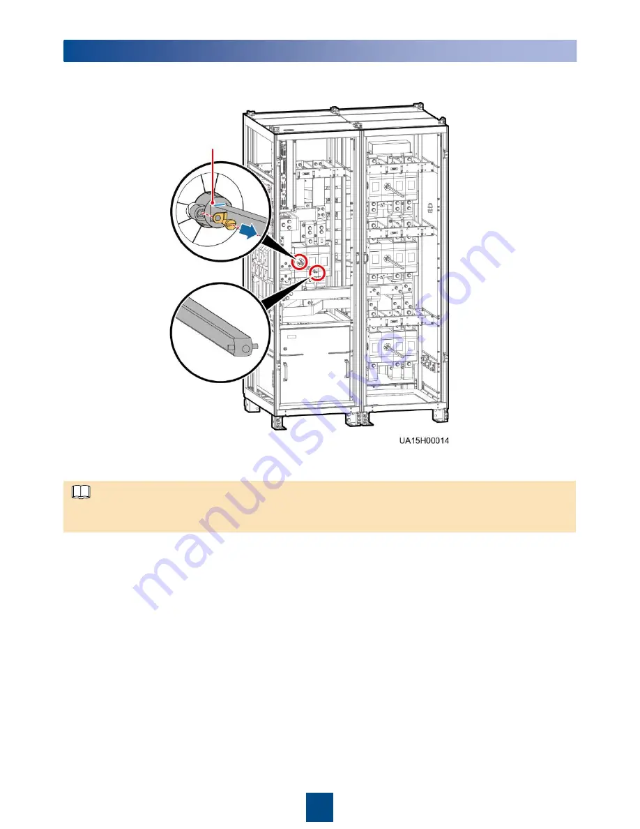
(Optional) Removing and Installing a Switch Extension Rod

Marked position

1. Remove  the switch extension  rod.

2. Install the switch extension  rod.

Keep the dowel level, insert the switch extension  rod to the marked position,  place washers properly, 
and tighten  the slotted screw to install  the switch extension  rod.

NOTE

Huawei Technologies Co., Ltd.

Huawei  Industrial  Base, Bantian,  Longgang

Shenzhen  518129 People's Republic  of China

www.huawei.com

Содержание UPS5000-A-800 Series

Страница 1: ...nfiguration Full configuration Weight 1530 kg 1610 kg Dimensions H x W x D 2000 mm x 2400 mm x 850 mm 1 Power unit 2 Control unit 3 Mains input switch only available in the full configuration model 4 Maintenance bypass switch 5 Output switch only available in the full configuration model 6 Bypass unit 7 Bypass input switch only available in the full configuration model Power cabinet Bypass cabinet...

Страница 2: ...ment damage may occur and the UPS faults caused are beyond the warranty scope of Huawei Install on the steel channel or floor Determine the mounting hole positions unit mm using a marking off template drill holes and install expansion sleeves based on site requirements A mounting holes on the steel channel B mounting holes on the floor 2 Installing the UPS Determining Installation Position 2 1 Com...

Страница 3: ...ts B Mounting holes on the floor M12x100 expansion bolts 2 Secure the UPS 4 Remove the front cover and No 10 protection panel from the bypass cabinet and the filler panel from the power cabinet 3 Install anchor baffle plates Bolts are not included NOTE ...

Страница 4: ...n there are two mains inputs 2 In the case of single mains you do not need to connect bypass input power cables and remove short circuit copper bars UPS Cable Connection Reference Prepare cables away from the cabinets to prevent scraps from falling inside Cable scraps may ignite and cause personal injury or device damage After cables have been installed clean the cabinets in a timely manner Keep t...

Страница 5: ...uration has only one switch cable maintenance bypass switch A UPS in full configuration has three switch cables mains input switch maintenance bypass switch and bypass input switch The following figure shows how to connect cables to a UPS in full configuration Connecting Signal Cables to Combined Cabinets 3 2 NOTE ...

Страница 6: ...onfiguration 04091625 06 Standard configuration SW1310 04091626 23 1 Remove the covers from the top of the cabinet drill holes in the covers for the power cables and battery cables attach grommet strips to the hole edges to protect the cables and reinstall the covers Connecting Power Cables and Signal Cables 3 3 Scenario 1 Routing Cables fromthe Top A Signal cable hole B Battery cable hole C Power...

Страница 7: ...rp exercise caution when removing the connecting copper bars to prevent personal injury Port Bolt Specifications Torque Mains input M16x50 120 N m Bypass input M16x50 120 N m Battery input M16x50 120 N m Output M16x50 120 N m PE M12x35 47 N m NOTE Ground cable The wire routed from the middle point between positive and negative battery strings is the neutral wire Take a battery string consisting of...

Страница 8: ... covers Output power cable Mains input power cable Ground cable Signal cable Battery cable The mains input and bypass input share the N busbar 2 Skip this step if the mains input and bypass input share a power source Remove the copper bars between the mains input and bypass input 3 Connect the ground cable power cables and signal cable Bypass input power cable no need to connect in case of only on...

Страница 9: ... and the cabinet using sealing putty Dustproof cover 4 Do not remove the dustproof cover before power on to prevent dust inside the UPS Sealing putty Sealing putty must be used as a whole and the gap can be sealed only from the top Paper protective film 5 Powering On and Starting the UPS 1 Before powering on the UPS ensure that the UPS has passed all check items in the UPS5000 Commissioning and Ac...

Страница 10: ... on initialization begins The MDU displays the Huawei logo and an initialization progress bar Starting the Inverter 5 2 System User LCD Preset Password WebUI Preset Password admin system administrator 000001 Changeme operator common user 000001 Changeme Initial Startup a If this is the initial startup set the language time date network parameters and system parameters on the Settings Wizard screen...

Страница 11: ...e USB port on the MDU Set System Info Settings Comm Settings WiFi Settings on the MDU The initial WiFi password is Changeme by default After login tap Power on password activation on the screen A message is displayed indicating whether to start the UPS Tap OK Enter Bar code and Verification code obtained from the MDU on the Offline Activation screen Tap Generate PWD to generate a startup password ...

Страница 12: ...rom the MDU 2 After confirming that the battery strings are properly connected turn on the battery string input circuit breaker If there are multiple battery strings turn on the circuit breaker for each battery string and then turn on the general circuit breaker between battery strings and the UPS The No battery alarm disappears from the MDU 3 Turn on the UPS downstream output switch to supply pow...

Страница 13: ...l the switch extension rod Keep the dowel level insert the switch extension rod to the marked position place washers properly and tighten the slotted screw to install the switch extension rod NOTE Huawei Technologies Co Ltd Huawei Industrial Base Bantian Longgang Shenzhen 518129 People s Republic of China www huawei com ...

Отзывы: