


14
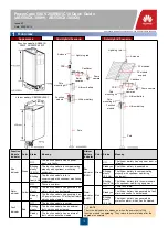
5. After you click
Open
, the copyright statement of the device is displayed on the HyperTerminal. Enter a valid user name and password as
prompted to log in to the command line interface (CLI) of the device. (The information displayed in the following figure is f or reference only.)
The preset user name for the device is
admin
and the password is
Admin@huawei
.
NOTE
Basic Configuration
15.3
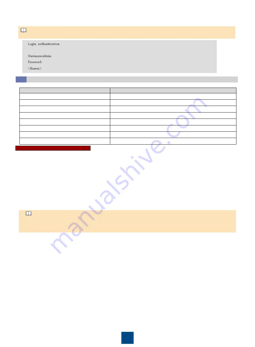
Parameter
Value (Example)
Device name
RouterA
Management VLAN
22
Service VLAN
1001 (video surveillance)
Management IP
10.0.0.1
Management gateway IP
10.0.0.254
Service interface range
Interfaces 0
–7
Uplink interface range
Interfaces 8
–9
Listening port of the TCP server
5000
Before configuring the parameters, determine the following data:
Configuring Basic Network Information
1. Run the
system-view
command to access the system view.
2. Run the
sysname
RouteA command to set the device name to RouteA. By default, the device host name is
Huawei
.
3. Run the
vlan batch
22 1001 command to create the service VLAN and management VLAN.
4. Run the
vlan
22 command to access the VLAN22 view.
5. Run the
description
management vlan command to set the VLAN description to
Management VLAN
.
6. Run the
quit
command to exit the VLAN view.
7. Run the
vlan
1001 command to access the VLAN1001 view.
8. Run the
description
Video command to set the VLAN description to
Video
.
9. Run the
quit
command to exit the VLAN view.
10.Run the
interface vlanif
22
command to access the Vlanif22 view.
11.Run the
ip address
10.0.0.1 255.255.255.0 command to set the IP address for the VLANIF interface.
12.Run the
quit
command to exit the VLANIF interface view.
13.Run the
interface
gigabitethernet 0/0/0 command to set a service interface. Access the 0/0/0 interface view and set other service ports by
referring to this interface setting.
The value of
interface-number
depends on the interface number. For example, if the interface number is 8, the value of
interface-
number
is
0/0/8
. For the interface number, see the silk screen on the device port.
Interfaces 8 and 9 support the 2.5GE optical module. It is recommended that interfaces 8 and 9 be used as uplink interfaces, and
interfaces 0
–7 be used as service interfaces.
NOTE
14.Run the
description
Cam command to set the interface description to
Cam
.
15.Run the
port link-type
access command to set the interface mode to
access
.
16.Run the
port default vlan
1001 command to set the default VLAN of the interface to
1001
.
17.Run the
quit
command to exit the interface view.
18.Run the
interface
gigabitethernet 0/0/8 command to set an uplink interface. Access the 0/0/8 interface view and set other uplink interfaces
by referring to this interface setting.
19.Run the
description
Uplink command to set the interface description to
Uplink
.
20.Run the
port link-type trunk
command to set the interface type to
Trunk
.
21.Run the
port trunk allow-pass vlan
22 1001 command to set the interface to allow VLAN22 and 1001 access.
22.Run the
quit
command to exit the interface view.
23.Run the
ip route-static
0.0.0.0 0.0.0.0 10.0.0.254 command to set the default route, next hop direction, and management gateway IP
address.


