background image

FusionModule2000 Smart Modular Data Center 
Installation Guide 

10 Installing the Aisle Containment 


Issue 02 (2018-03-31) 

Huawei Proprietary and Confidential                                     

Copyright © Huawei Technologies Co., Ltd. 

146 


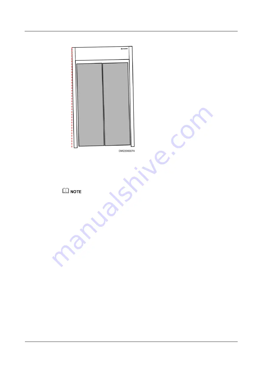
Figure 10-58


Door panels tilting at both sides 


2.


If there is a gap between the door panel and upper frame mounting kit (a corner tilts 
downwards), you can push up the lower part of the post or add a spacer between the 
upper frame mounting kit and the post. Pull the lower end of the post outwards if a 
corner of a door panel tilts upwards. 


If the door gap is still uneven after the preceding measures are taken, remove and reinstall the rubber 
strip on one door panel. Adjust the rubber strip positions during installation to verify that the door panel 
edges are in close contact. 

Содержание FusionModule2000 V500R003C10

Страница 1: ...FusionModule2000 Smart Modular Data Center V500R002C03 Installation Guide Issue 02 Date 2018 03 31 HUAWEI TECHNOLOGIES CO LTD ...

Страница 2: ... Huawei and the customer All or part of the products services and features described in this document may not be within the purchase scope or the usage scope Unless otherwise specified in the contract all statements information and recommendations in this document are provided AS IS without warranties guarantees or representations of any kind either express or implied The information in this docum...

Страница 3: ...n engineers Commissioning engineers Maintenance engineers Technical support engineers Symbol Conventions The symbols that may be found in this document are defined as follows Symbol Description Indicates an imminently hazardous situation which if not avoided will result in serious injury or death Indicates a potentially hazardous situation which if not avoided could result in serious injury or dea...

Страница 4: ...TE is used to address information not related to personal injury equipment damage or environment deterioration Change History Changes between document issues are cumulative The latest document issue contains all updates made in previous issues Issue 02 2018 03 31 Updated the section Optional Installing a 600 mm Wide Air Conditioner Enclosure Frame Issue 01 2017 09 20 This issue is the first releas...

Страница 5: ...and Distribution Cabinet Scenario Dual Row 19 2 8 2 Power Supply and Distribution Cabinet Scenario Single Row 20 2 8 3 Smart Busway Scenario Dual Row 21 2 8 4 Smart Busway Scenario Single Row 22 3 Smart Module Layout Requirements 24 3 1 Layout Requirements for Standard Dual Row Aisle Containment 24 3 2 Layout Requirements for Standard Single Row Aisle Containment 25 3 3 Layout Requirements for Dua...

Страница 6: ...0 A 25 kW Air Conditioners 69 7 1 1 Optional Installing Top Frames Top Pipe Routing 69 7 1 2 Optional Installing Top Frames Bottom Pipe Routing 71 7 1 3 Optional Installing a 300 mm Wide Air Conditioner Adaptive Frame 72 7 1 4 Optional Installing a Top Frame for an Adaptive Frame 75 7 2 Optional Installing NetCol5000 A 42 kW Air Conditioners 76 7 2 1 Optional Installing a 600 mm Wide Air Condition...

Страница 7: ...midifiers 171 14 Installing Power Supply and Distribution Devices 176 14 1 Optional Installing the UPS Outside the Smart Module 176 14 2 Optional Installing a Battery Cabinet Outside the Smart Module 176 14 3 Optional Installing Batteries 176 14 4 Optional Installing an Air Conditioner PDB 177 15 Installing Monitoring Devices 179 15 1 Equipment Layout in the Network Cabinet 179 15 1 1 Optional Ins...

Страница 8: ...ensor 234 15 9 1 Laying Out the Water Detection Cable Dual Row Scenario 235 15 9 2 Laying Out the Water Detection Cable Single Row Scenario 237 15 9 3 Connecting a Cable to the WLDS900 Water Sensor 238 15 9 4 Routing a Water Detection Cable 240 15 10 Installing a GSM Modem 242 16 Optional Installing In Room Access Control Devices and Cameras 244 16 1 Layout of the In Room Access Control System 244...

Страница 9: ...rs 284 17 8 4 Optional Connecting rPDU Cables 285 17 9 Connecting Cables to the Cooling System 289 17 10 Installing Cables for the Facility Management System 289 17 11 Cable Routes for the Aisle Lighting System 289 17 12 Optional Connecting Cables for the In Room Access Control and Camera System 290 A Appendix 293 A 1 Installing an Expansion Bolt 293 A 2 Cable Routes Inside an IT Cabinet 294 A 3 P...

Страница 10: ... and safety precautions in this document Device damage due to abnormal natural factors Overview To ensure safety of humans and the equipment pay attention to the safety symbols on the equipment and all the safety instructions in this document The NOTICE WARNING CAUTION and DANGER marks in this document do not represent all the safety instructions They are only supplements to the safety instruction...

Страница 11: ...n Before operating the device check the electrical connection of the device to ensure that it is securely grounded Human Safety Before operating a device wear electrostatic discharge ESD clothes ESD gloves and an ESD wrist strap Do not wear jewelry or watches when you operate the device In the case of fire immediately leave the building or the equipment room and turn on the fire alarm bell or make...

Страница 12: ...ntact between the core of the power cable and the conductor may generate electric arcs or sparks which may cause fire or hurt human eyes Before installing or removing the power cable turn off the power switch Before connecting a power cable verify that the label on the power cable is correct Electrostatic Discharge The static electricity generated by human bodies may damage the electrostatic sensi...

Страница 13: ...andling and battery connection methods carefully Any incorrect operation of batteries may cause danger When operating batteries avoid short circuits and electrolyte overflow or leakage Electrolyte overflows may damage the device It will corrode metal parts and circuit boards and ultimately damage the device and cause short circuits of circuit boards Batteries have a high power capacity Short circu...

Страница 14: ...es Place and secure lead acid batteries horizontally to prevent inflammation or device corrosion due to flammable gas emitted from batteries Lead acid batteries emit flammable gas when used Therefore store these batteries in well ventilated areas and take fire prevention measures Battery Temperature High temperatures may result in battery distortion damage and electrolyte overflow When the battery...

Страница 15: ...te electromagnetic shielding performance and damage the internal cables and metal scraps generated during drilling may short circuit a circuit board Before drilling holes on the rack first remove the cables inside the rack To protect your eyes from metal shavings wear a pair of goggles when drilling holes Before drilling holes wear protective gloves When drilling holes prevent metal shards from dr...

Страница 16: ...ht of the device 1 5 Others This section describes the precautions to be taken when binding signal cables and laying out power cables at a low temperature Binding Signal Cables Signal cables must be bound separately from strong current cables and high voltage cables Routing Power Cables When the temperature is low violent strike or vibration may damage the cable sheathing To ensure safety comply w...

Страница 17: ... the forks of the pallet truck in the middle position to ensure balance Transport devices by railway sea or good road No excessive tilt or jolt is allowed during the transportation The device can only be tilted for at most 15 during loading and unloading as shown in Figure 2 1 To prevent the cabinet from falling over secure it to a pallet truck using ropes before moving it Move the cabinet with ca...

Страница 18: ...cceptance Context Unpack and inspect all cabinets mechanical parts and components Check that all the items are intact and comply with the packing list on the presence of both the project supervisor and customer Procedure Step 1 Unpack the carton labeled Contain Packing List and take out the Packing List Step 2 Check all items against the Packing List Step 3 If an item is incorrect or missing conta...

Страница 19: ...vironment meets the requirements before installation Table 2 1 Installation environment checklist Check Item Criteria Check Result Floor load bearing capacity Standard live load of the main equipment room 8 12 kN m2 If the battery cabinet is placed inside the module use the standard live load of the main equipment room as a reference Suspended load of the main equipment room 1 2 kN m2 Standard liv...

Страница 20: ...The equipment room ground grid has a ground resistance no greater than 10 ohms If the ground resistance exceeds 10 ohms ensure that the equivalent ground radius of the ground grid exceeds 5 meters Ground bars are deployed over the cable tray or under the raised floor Passed Failed Monitoring port One LAN switch Ethernet port connects to the customer subnet to monitor devices inside the module Opti...

Страница 21: ...allation Preparations Issue 02 2018 03 31 Huawei Proprietary and Confidential Copyright Huawei Technologies Co Ltd 12 If any of the requirements is not met contact Huawei technical support 2 4 Site Requirements Figure 2 3 Single row scenario Figure 2 4 Dual row scenario ...

Страница 22: ... Power Distribution BOX T Quick Installation Guide 02402732 005 PDU8000 Power Distribution BOX T Quick Installation Guide 02402732 006 iBAT iBAT 2 0 CIM01C2 User Manual Cooling system NetCol5000 A 25 kW air cooled in row precision air conditioner NetCol5000 A 25 kW Air Cooled In row Precision Air Conditioner Quick Guide 300 mm Wide NetCol5000 A 42 kW air cooled in row precision air conditioner Net...

Страница 23: ...n use Click on the ECC800 and the NetEco WebUI to obtain the ECC800 and NetEco versions 2 6 Tools and Instruments This section lists the tools and instruments required for installation Table 2 3 General tools Name Specifications and Appearance Protective gloves Marker Measuring tape 5 m Level Step ladder 2 m Phillips screwdriver Phase sequence meter Flat head screwdriver 2 5 mm Adjustable wrench 6...

Страница 24: ...pecifications and Appearance Electric screwdriver Hand drill Φ3 Φ3 7 Φ4 Φ4 5 Φ5 Φ6 Φ10 and Φ12 drill bits Hammer drill Φ16 drill bit Heat gun Laser locator Utility knife Electrician s knife Impact tool Polyvinyl chloride PVC insulation tape Needle nose pliers Diagonal pliers RJ45 crimping tool Crimping tool Wire stripper Hydraulic pliers Wire clippers Cable ties Multimeter Electroprobe Brush ...

Страница 25: ...socket screwdriver Flashlight Clamp meter N A N A NOTE This table may not list some tools required at specific sites Onsite installation personnel and technical support personnel should prepare tools based on site requirements Table 2 4 Transportation and unpacking tools Tool Appearance Specifications and Name Pallet truck Diesel forklift Lifting rope bearing capacity 400 kg Lever bearing capacity...

Страница 26: ... Vacuum pumpc Thermocouple temperature sensor Antifreeze gloves Electronic scale Reducing valvee N A N A N A N A N A N A a For equipment with humidifiers ensure that the water pipe thread sealant is able to resist temperatures higher than 85 C and the following requirements are met Applicable to all pipe materials Anaerobic metal pipe thread sealant with PTEF as the padding Glycol solution resista...

Страница 27: ...he rate flow between 2 L s and 4 L s is recommended Absolute vacuum 60 Pa d Dry nitrogen e A reducing valve needs to install to the outlet of the nitrogen steel vessel and the reducing valve range 4 0 MPa 2 7 Personnel Requirements Only trained and qualified personnel who fully understand basic safety precautions are allowed to install and operate a modular data center Huawei will not be liable fo...

Страница 28: ...on PDC with batteries and UPS deployed outside the aisle containment The PDC in smart module A with batteries deployed outside is an integrated UPS with batteries deployed outside the aisle containment It is recommended that two air conditioners with the heating and humidification functions be installed for the standard configuration In the dual row aisle containment the two air conditioners shoul...

Страница 29: ... Technologies Co Ltd 20 Figure 2 6 Exterior of the dual row aisle containment 1 End door 2 Flat or rotating skylight 3 For the alarm beacon 4 For the pad 5 Control skylight 6 Cable trough 7 Smart ETH gateway 8 For the access control 9 Cabinet 2 8 2 Power Supply and Distribution Cabinet Scenario Single Row Figure 2 7 Floor plan of the single row aisle containment ...

Страница 30: ...yright Huawei Technologies Co Ltd 21 Figure 2 8 Exterior of the single row aisle containment 1 End door 2 Flat or rotating skylight 3 Control skylight 4 Cable trough 5 Smart ETH gateway 6 Cabinet 7 For the alarm beacon 8 For the pad 9 For the access control 2 8 3 Smart Busway Scenario Dual Row Figure 2 9 Floor plan of the dual row aisle containment ...

Страница 31: ...td 22 Figure 2 10 Exterior of the dual row aisle containment 1 General input unit 2 Control skylight 3 For the alarm beacon 4 Power distribution unit 5 Busbar trunking unit 6 Flat or rotating skylight 7 Cable trough 8 Cabinet 9 For the pad 10 For the access control device 11 End door 2 8 4 Smart Busway Scenario Single Row Figure 2 11 Floor plan of the single row aisle containment ...

Страница 32: ...and Confidential Copyright Huawei Technologies Co Ltd 23 Figure 2 12 Exterior of the single row aisle containment 1 General input unit 2 Control skylight 3 For the alarm beacon 4 Power distribution unit 5 Busbar trunking unit 6 Flat or rotating skylight 7 Cable trough 8 Cabinet 9 For the pad 10 For the access control 11 End door ...

Страница 33: ... module based on the onsite engineering layout diagram Step 2 Use a laser locator to mark two lines that are perpendicular to each other in a corner of the planned installation position If no laser locator is available use a right angle and thin rope to mark the two perpendicular lines Step 3 Place one corner of the marking off template at the crossing point of the perpendicular lines to determine...

Страница 34: ... locator Step 4 Use a measuring tape to measure the aisle distance and mark the position for the end cabinet in the other row in the same way End 3 2 Layout Requirements for Standard Single Row Aisle Containment Prerequisites The floor levelness meets engineering requirements levelness tolerance 3 mm Preparations Tools laser locator marker measuring tape Document onsite engineering layout diagram ...

Страница 35: ...ight angle and thin rope to mark the two perpendicular lines Step 3 Place one corner of the marking off template at the crossing point of the perpendicular lines to determine the position for an end cabinet Use a marker to mark the outline of the marking off template and the mounting holes for the cabinet on the floor If there is no need to secure the cabinet to the floor mark only the outline of ...

Страница 36: ...olumn This section describes the column position in the scenario with a column relative to the adjustable skylight sealing plates and cable trays Figure 3 3 Legend 1 Cabinet 2 Single layer of cable tray 3 Double layer of cable trays 4 Flat or rotating skylight 5 Adjustable skylight 6 Sealing plate 7 Column in the equipment room If a column in the data center is irregular ensure that the maximum cr...

Страница 37: ... A 800 mm Cabinet places on both sides of the column are left blank and sealed by sealing plates Directions of the concave sides of the sealing plates are shown in Figure 3 4 Install cable trays over the cabinets on both sides of the blank cabinet places for routing strong current and weak current cables Install an adjustable skylight over the aisle containment The area to be covered by the adjust...

Страница 38: ... 800 mm and B 400 mm Cabinet places on both sides of the column are left blank and sealed by sealing plates Directions of the concave sides of the sealing plates are shown in Figure 3 5 Install cable trays over the cabinets on both sides of the blank cabinet places for routing strong current and weak current cables Install an adjustable skylight over the aisle containment The area to be covered by...

Страница 39: ... are left blank and sealed by sealing plates Directions of the concave sides of the sealing plates are shown in Figure 3 6 Install cable trays over the cabinets on both sides of the blank cabinet places If the cable trays cannot be installed in combined mode install them in layered mode the upper for routing weak current cables while the lower for routing strong current cables Install an adjustabl...

Страница 40: ...lank and sealed by sealing plates Directions of the concave sides of the sealing plates are shown in Figure 3 7 Install cable trays over the cabinets on both sides of the blank cabinet places If the cable trays cannot be installed in combined mode install them in layered mode the upper for routing weak current cables while the lower for routing strong current cables Install an adjustable skylight ...

Страница 41: ...ons of the concave sides of the sealing plates are shown in Figure 3 8 Install cable trays over the cabinets on both sides of the blank cabinet places If the cable trays cannot be installed in combined mode install them in layered mode the upper for routing weak current cables while the lower for routing strong current cables Install flat or rotating skylights over the aisle containment If sealing...

Страница 42: ...Column This section describes the column position in the scenario with a column relative to the adjustable skylight sealing plates and cable trays Figure 3 9 Legend 1 Cabinet 2 Single layer of cable tray 3 Double layer of cable trays 4 Flat or rotating skylight 5 Adjustable skylight 6 Sealing plate 7 Column in the equipment room If a column in the data center is irregular ensure that the maximum c...

Страница 43: ...ment A 800 mm Cabinet places on the column side are left blank and sealed by sealing plates Directions of the concave sides of the sealing plates are shown in Figure 3 10 Install cable trays over the cabinets on both sides of the blank cabinet places for routing strong current and weak current cables Install an adjustable skylight over the aisle containment The area to be covered by the adjustable...

Страница 44: ...ce A 800 mm and B 400 mm Cabinet places on the column side are left blank and sealed by sealing plates Directions of the concave sides of the sealing plates are shown in Figure 3 11 Install cable trays over the cabinets on both sides of the blank cabinet places for routing strong current and weak current cables Install an adjustable skylight over the aisle containment The area to be covered by the...

Страница 45: ...left blank and sealed by sealing plates Directions of the concave sides of the sealing plates are shown in Figure 3 12 Install cable trays over the cabinets on both sides of the blank cabinet places If the cable trays cannot be installed in combined mode install them in layered mode the upper for routing weak current cables while the lower for routing strong current cables Install an adjustable sk...

Страница 46: ...ank and sealed by sealing plates Directions of the concave sides of the sealing plates are shown in Figure 3 13 Install cable trays over the cabinets on both sides of the blank cabinet places If the cable trays cannot be installed in combined mode install them in layered mode the upper for routing weak current cables while the lower for routing strong current cables Install an adjustable skylight ...

Страница 47: ...ons of the concave sides of the sealing plates are shown in Figure 3 14 Install cable trays over the cabinets on both sides of the blank cabinet places If the cable trays cannot be installed in combined mode install them in layered mode the upper for routing weak current cables while the lower for routing strong current cables Install flat or rotating skylights over the aisle containment If sealin...

Страница 48: ...FusionModule2000 Smart Modular Data Center Installation Guide 3 Smart Module Layout Requirements Issue 02 2018 03 31 Huawei Proprietary and Confidential Copyright Huawei Technologies Co Ltd 39 ...

Страница 49: ...s Assume that each row of cabinets is configured with N bases If N is less than 5 you can install all the bases at a time After installation check that the total length of each row of bases is the sum of nominal widths of all bases tolerance 3 mm to 0 mm If N is greater than or equal to 5 you are advised to install five bases at a time After installation check that the total length of the bases is...

Страница 50: ...al Copyright Huawei Technologies Co Ltd 41 Figure 4 1 Single row base layout unit mm Figure 4 2 Dual row base layout unit mm 4 2 Installing Bases with Adjustable Dimensions Context A base with adjustable dimensions can be 300 mm 600 mm or 800 mm wide and applies to the PDC battery cabinet IT cabinet network cabinet and air conditioner cabinet ...

Страница 51: ...stable 1000 mm 1100 mm or 1200 mm Height adjustable 410 700 mm depth adjustable 1000 mm 1100 mm or 1200 mm 800 mm wide base Height adjustable 270 410 mm depth adjustable 1000 mm 1100 mm or 1200 mm Height adjustable 410 700 mm depth adjustable 1000 mm 1100 mm or 1200 mm Preparations Tools ruler marker torque wrench Phillips screwdriver right angle hammer drill φ16 drill bit level Materials base and...

Страница 52: ...idential Copyright Huawei Technologies Co Ltd 43 Figure 4 3 Measuring the ESD floor height 2 Adjust the base height to H and tighten the height locking bolts on the feet Figure 4 4 Tightening height locking bolts Step 2 Assemble the base 1 Adjust the base depth based on the cabinet depth 2 Tighten the bolt assembly on the telescopic rod ...

Страница 53: ... and the base and then tighten the bolt assembly Step 3 Use a right angle to position the end cabinet base and ensure that the outline of the upper surface of the base aligns with the cabinet bottom outline on the floor Figure 4 6 Positioning the first base Step 4 Use the end cabinet base as the reference and place other cabinet bases Step 5 Check that the installation position meets the requireme...

Страница 54: ...rill bit to drill holes to a depth of 52 60 mm at the installation position and install expansion sleeves Step 8 Move the base back install expansion bolts and partially tighten them Step 9 Measure the levelness of the base using a level as shown by 1 in Figure 4 8 If a base is not level put washers under it as shown by 2 in Figure 4 8 Figure 4 8 Leveling a base Step 10 Tighten expansion bolts as ...

Страница 55: ...gure 4 9 Connecting bases Step 13 Screw the floor holder to the base as shown by 2 in Figure 4 9 End Follow up Procedure Check the installation and ensure that adjacent bases are in close contact with each other and the gap is even 4 3 Installing Bases with Fixed Dimensions 4 3 1 Optional Adjusting Adjustable Feet of Air Conditioner Bases 300 mm Wide Context A 300 mm wide air conditioner base is u...

Страница 56: ...00 mm wide air conditioner base Preparations Tool Phillips screwdriver Material air conditioner base 300 mm wide Document base installation position diagram Procedure Step 1 Remove the four M6 screws from adjustable feet and set them aside Figure 4 11 Removing screws from adjustable feet Step 2 Move the adjustable feet to the mounting holes on the base according to the depth of the air conditioner...

Страница 57: ...onditioner base to the cabinet front close to the front door of the cabinet Step 3 Secure the adjustable feet using the four M6 screws removed before Figure 4 12 Securing adjustable feet End 4 3 2 Optional Adjusting Adjustable Feet of Air Conditioner and PDC Bases 600 mm Wide Context A 600 mm wide adjustable base is used for a 600 mm wide air conditioner or PDC The BOM number of a 600 mm wide adju...

Страница 58: ...ir conditioner in a hot aisle containment 2 Used for an air conditioner in a cold aisle containment or a PDC in a hot aisle containment Preparations Tool Phillips screwdriver Material base 600 mm wide Document base installation position diagram Procedure Step 1 Remove the four M6 screws from adjustable feet and set them aside Figure 4 14 Removing screws from adjustable feet Step 2 Move the adjusta...

Страница 59: ...cabinet Move the adjustable feet of the PDC base to the cabinet rear close to the rear door of the cabinet Step 3 Secure the adjustable feet using the four M6 screws removed before Figure 4 15 Securing adjustable feet End 4 3 3 Installing Bases with Fixed Dimensions Prerequisites Adjustable feet of bases have been adjusted Preparations Tools marker socket wrench torque wrench hammer drill φ16 dril...

Страница 60: ...ked FRONT facing the aisle containment Step 2 Mark base mounting holes on the concrete floor using a marker Step 3 Move away the base use a hammer drill with a φ16 drill bit to drill holes to a depth of 52 60 mm at the installation position and install expansion sleeves Step 4 Move the base back install expansion bolts and partially tighten them Step 5 Optional Put a washer under the base to level...

Страница 61: ...here are two solutions of grounding bases Connect the base ground point to the general ground bar of the equipment room Connect the base ground point to the cabinet ground bar If the base ground point is to be connected to the cabinet ground bar perform the grounding operation after cabinets have been installed Adjustable bases and bases with fixed dimensions can be grounded in the same way This s...

Страница 62: ...base ground cable to any of the base ground points and connect the other end to the general ground bar of the equipment room Alternatively connect one end of the base ground cable to any of the base ground points and connect the other end to the ground bar at the rear door bottom inside the cabinet Figure 4 18 Base grounding diagram 1 Base ground point Figure 4 19 Connecting the ground cable betwe...

Страница 63: ...ng the PDC in the installation position unpack it with care to avoid scratches Keep the PDC steady during unpacking If the PDC installation environment is in poor condition and the PDC needs to be stored for a long time after it is unpacked take measures to prevent dust It is recommended that the PDC be wrapped with the original plastic coat Preparations Tools forklift truck adjustable wrench diag...

Страница 64: ...g list If some fittings are missing or do not comply with the packing list record the information and contact your local Huawei office immediately Step 5 After verifying that the PDC is intact remove the L shaped brackets securing the cabinet and pallet and insert the two sliding plates under the pallet Ensure that the sliding plates are properly installed in step 2 in Figure 5 1 otherwise the sli...

Страница 65: ...on position If there are bases place the PDC on the base End 5 2 Installing a Tail Frame For details see the document delivered with the PDC 5 3 Optional Installing a Top Frame Context In 2200 mm scenarios a top frame is used to increase the cabinet height by 200 mm Preparations Tool Phillips screwdriver Material top frame Procedure Step 1 Remove the two M5x10 tapping screws that secure the front ...

Страница 66: ...e top frame the side with FRONT facing upwards and the end near FRONT facing the cabinet front door as shown by 2 in Figure 5 3 Step 3 Secure the top frame 1 Use four M8x20 screw assemblies to secure the top frame to the cabinet as shown by 3 and 4 in Figure 5 3 2 Install two M5x10 tapping screws at the front of the top frame to set up equipotential bonding between the cabinet and the top frame as...

Страница 67: ...logies Co Ltd 58 6 Installing the Network Cabinet IT Cabinet and Battery Cabinet 6 1 Moving the Network Cabinet IT Cabinet and Battery Cabinet Preparations Tool adjustable wrench Procedure Step 1 Move the cabinet to the planned installation position Step 2 Remove the screws that secure the cabinet to the pallet If the cabinet needs to be secured save the screws you removed from the pallet for futu...

Страница 68: ...se place the cabinet on the base End 6 2 Optional Installing Side Plates for IT Cabinets Context If an IT cabinet is not equipped with side plates and placed in the end position side plates need to be installed to ensure that the outer side of an end cabinet has side plates If two cabinets share side plates and placed in the end position the side plates need to be adjusted to ensure that the outer...

Страница 69: ...d 60 Figure 6 2 Installing a floating nut Step 2 Optional Remove side plates based on the labels on the side plates to be adjusted Step 3 Secure each side plate to the outer side of the end cabinet Install two side plates for each end cabinet one in the upper part and the other in the lower part Figure 6 3 Installing a cabinet side plate Step 4 Optional After adjusting side plates remove the label...

Страница 70: ...op and reinstall the rodent proof mesh Cut the rodent proof mesh based on the cable thickness using diagonal pliers If the opening is too large unwanted things may fall into the cabinet through the opening End Follow up Procedure Before connecting the power plug of a device to the rPDU loosen the locking device on the rPDU After connecting the power plug tighten the locking device 6 4 Optional Tak...

Страница 71: ... Technologies Co Ltd 62 Figure 6 4 Taking out industrial connectors Step 2 Lay out the industrial connectors and cables on the cabinet top and reinstall the rodent proof mesh Cut the rodent proof mesh based on the cable thickness using diagonal pliers If the opening is too large unwanted things may fall into the cabinet through the opening Figure 6 5 Laying out industrial connectors and cables End...

Страница 72: ...battery cabinet Ensure that there are side plates on the outer sides of the main and auxiliary battery cabinets and there is no side plate between the adjacent battery cabinets After adjusting the side plate of the battery cabinet remove the label which indicates side plate adjustment from the main battery cabinet 6 6 Optional Installing a Battery Cabinet Top Frame The top frame of a battery cabin...

Страница 73: ...ound bar on the topmost position of the rack rail outside and secure the ground bar using the M8 screws removed earlier Install the horizontal ground bar in the battery cabinet or IT cabinet adjacent to the PDC Figure 6 7 Installing a horizontal ground bar End 6 8 Optional Installing a Vertical Ground Bar Context Install the vertical ground bar in the IT cabinet that is closest to the PDC The BOM ...

Страница 74: ...four M4 screws to secure the vertical ground bar to the right mounting bar The specific securing positions are the screw holes in the middle of the 04 U 14 U 29 U and 39 U positions Figure 6 8 Installing a vertical ground bar End 6 9 Optional Setting a Cabinet Code Lock Context The cabinet code lock can be unlocked with a key or password If you do not need the password function you can use a key t...

Страница 75: ...ure 6 9 Cabinet code lock 1 Lock base 2 Lock head 3 Wheel 4 Password knob Verifying the Preset Password Step 1 Enter the password and turn the knob 180 degrees counterclockwise to unlock If the cabinet can be unlocked the preset password of the code lock is 0 0 0 Change the preset password in a timely manner If the cabinet cannot be unlocked the preset password of the code lock is not 0 0 0 You ne...

Страница 76: ... Battery Cabinet Issue 02 2018 03 31 Huawei Proprietary and Confidential Copyright Huawei Technologies Co Ltd 67 Figure 6 10 Unlocking with a password End Retrieving the Password Step 1 Insert the cabinet key into the lock hole and turn it 180 degrees counterclockwise to unlock Figure 6 11 Unlocking with a key ...

Страница 77: ... the calibration hole with the semicircular notch of the wheel There is a semicircular notch and a square notch on the wheel of the code lock Align the calibration hole with the semicircular notch After the semicircular notches of the three password wheels are aligned with the calibration hole the displayed password is the password set for the last time After you retrieve the password you are advi...

Страница 78: ...ipe routing Choose either scenario 7 1 1 Optional Installing Top Frames Top Pipe Routing Prerequisites If the IT cabinet is 1200 mm deep install top frames after installing air conditioner enclosure frames Preparations Tool Phillips screwdriver Procedure Step 1 Remove the two M5x10 tapping screws that secure the front door sealing plate on the top of the cabinet as shown by 1 in Figure 7 1 Step 2 ...

Страница 79: ...tapping screws and the six M4x10 countersunk screws to secure the rear plate to the top frame and clamp the rear decorative plate as shown by 1 and 2 in Figure 7 2 2 Use four M8x20 screw assemblies to secure the top frame to the cabinet as shown by 3 and 4 in Figure 7 2 3 Install two M5x10 tapping screws at the front of the top frame to set up equipotential bonding between the cabinet and the top ...

Страница 80: ...e Procedure Step 1 Remove the two M5x10 tapping screws that secure the front door sealing plate on the top of the cabinet as shown by 1 in Figure 7 3 Step 2 Place the top frame and ensure that the side with FRONT faces upwards toward the cabinet front door as shown by 2 in Figure 7 3 Step 3 Secure the top frame 1 Use four M8x20 screw assemblies to secure the top frame to the cabinet as shown by 3 ...

Страница 81: ... that the lengths of the two cabinet rows are the same The BOM number of an air conditioner adaptive frame is 21242047 An adaptive frame consists of a front panel a rear panel and a top panel The front panel and rear panel are the same Preparations Tool Phillips screwdriver Materials front panel rear panel top panel connecting kit Procedure Step 1 Optional If the cabinet depth is 1200 mm use three...

Страница 82: ...awei Proprietary and Confidential Copyright Huawei Technologies Co Ltd 73 Figure 7 5 Installing connecting kits Step 3 Clamp the front panel between cabinets and ensure that its surface is flush with the cabinet doors Use connecting kits and M4x10 screw assemblies to connect the front panel to the adjacent cabinets ...

Страница 83: ...ntial Copyright Huawei Technologies Co Ltd 74 Figure 7 6 Securing an adaptive frame Step 4 Install the rear panel in the same way Step 5 Use four M4x10 screw assemblies to secure the top panel to the front and rear panels as shown by 1 in Figure 7 7 Do not over tighten the top panel of the adaptive frame Otherwise the top panel will be uneven ...

Страница 84: ...x10 tapping screws to secure the top panel to the adjacent cabinets as shown by 2 in Figure 7 7 End 7 1 4 Optional Installing a Top Frame for an Adaptive Frame Preparations Tool Phillips screwdriver Material top frame for an adaptive frame Procedure Step 1 Place the top frame and ensure that the side with FRONT faces upwards toward the front of the adaptive frame Step 2 Use screw assemblies to sec...

Страница 85: ...ent delivered with the equipment or obtain the required document according to the section Documentation Preparations If there are bases install air conditioners on the bases The installation of air conditioner top frames applies to scenarios with top or bottom pipe routing Choose either scenario 7 2 1 Optional Installing a 600 mm Wide Air Conditioner Enclosure Frame Context To increase the equipme...

Страница 86: ...closure frame 1 Enclosure frame Preparations Tool Phillips screwdriver Materials enclosure frame M5 tapping screw Procedure Step 1 Open the front door and remove the LCD power cable and front door ground cable Then lift and remove the front door Step 2 Use four M5 tapping screws to secure one upper sealing plate to the enclosure frame There are two upper sealing plates and the one used in this ste...

Страница 87: ...ei Proprietary and Confidential Copyright Huawei Technologies Co Ltd 78 Figure 7 10 Upper sealing plate of an enclosure frame Figure 7 11 Installing the upper sealing plate of an enclosure frame Step 3 Remove one bolt fastener four cabinet connecting kits and two front door mounting kits Save the removed accessories ...

Страница 88: ... Center Installation Guide 7 Installing Air Conditioners Issue 02 2018 03 31 Huawei Proprietary and Confidential Copyright Huawei Technologies Co Ltd 79 Figure 7 12 Removing the front door mounting kits Step 4 Secure the enclosure frame ...

Страница 89: ...e frame Step 5 Install the mounting kits removed in Step 3 at the corresponding positions on the enclosure frame Step 6 Install the front door on the enclosure frame Step 7 Install the LCD power cable and connect the ground cable under the front door to the ground point marked on the enclosure frame Step 8 Cut the cable ties securing the LCD power cable to the cabinet and stretch the power cable t...

Страница 90: ...orative plate from the top frame and then remove the four M5x10 tapping screws and the six M4x10 countersunk screws from the rear plate of the top frame as shown by 2 and 3 in Figure 7 14 Then remove the rear plate Step 3 Place the top frame and ensure that the side with FRONT faces upwards toward the cabinet front door as shown by 4 in Figure 7 14 Step 4 Secure the top frame 1 Use the four M5x10 ...

Страница 91: ...bonding between the cabinet and the top frame as shown by 3 in Figure 7 15 End 7 2 3 Optional Installing Top Frames Bottom Pipe Routing In the scenario where air conditioner pipes are routed from the bottom the top frame is installed in the same way as the top frame of a PDC For details see section Installing a Top Frame under Installing the PDC 7 3 Installing Air Conditioner Outdoor Units and Rou...

Страница 92: ...ch level Phillips screwdriver Document cabinet layout diagram Procedure Step 1 Optional Partially secure the cabinets to the bases If bases are required perform this step for the PDC network cabinet IT cabinet 600 mm wide air conditioner and 300 mm wide M type air conditioner with feet If bases are required go to Step 3 for cabinets without feet 1 Align the mounting holes on the cabinet with those...

Страница 93: ...8 Combining Cabinets Issue 02 2018 03 31 Huawei Proprietary and Confidential Copyright Huawei Technologies Co Ltd 84 Figure 8 1 Partially securing the cabinet to its base Step 2 Level the cabinets and ensure that the height deviation of cabinets is less than 3 mm ...

Страница 94: ... to lower it Anchor bolts can be adjusted within a range of 0 8 mm Put a level at the bottom of the cabinet in width and depth directions and check that the air bubble is in the middle between the two lines marked on the glass tube Figure 8 2 Leveling a cabinet 1 Level Step 3 Optional Secure cabinets on the bases Perform this step if bases are required For the PDC network cabinet IT cabinet 600 mm...

Страница 95: ...ight Huawei Technologies Co Ltd 86 Figure 8 3 Securing the cabinet For the 300 mm wide Arki type air conditioner Align the mounting holes on the front and rear of the air conditioner with those on the top of the base and secure the air conditioner to the base using M10 screws in the fitting bag Figure 8 4 Securing an air conditioner to the base ...

Страница 96: ...Copyright Huawei Technologies Co Ltd 87 Step 4 Combine adjacent cabinets 1 Remove the M5x10 tapping screws that secure the connecting kit and then remove the connecting kit 2 Remove M4x10 screw assemblies from the position for combining cabinets 3 Secure the connecting kit using the M4x10 screw assemblies Figure 8 5 Combining cabinets End ...

Страница 97: ...hnologies Co Ltd 88 9 Grounding Cabinets Choose either the M type or S type grounding solution You are advised to choose the M type grounding solution if it is available M type Grounding Cabinets are grounded by cables connected from the main ground bars shown by 2 in Figure 9 3 to the nearby ground grid Figure 9 1 M type grounding diagram single row cabinets ...

Страница 98: ...is solution is used it should be customized Figure 9 3 shows the cabinet ground points Connect cabinet ground cables as follows Connect the cabinet ground bar or ground point to the branch ground bar of the battery cabinet or IT cabinet near the PDC and then connect the branch ground bar to the main ground bar inside the PDC If no branch ground bar is installed connect the cabinet ground bar or gr...

Страница 99: ...e 9 Grounding Cabinets Issue 02 2018 03 31 Huawei Proprietary and Confidential Copyright Huawei Technologies Co Ltd 90 Figure 9 3 Cabinet ground points 1 Cabinet branch ground bar 2 Cabinet main ground bar Figure 9 4 S type grounding diagram single row cabinets ...

Страница 100: ...0 Smart Modular Data Center Installation Guide 9 Grounding Cabinets Issue 02 2018 03 31 Huawei Proprietary and Confidential Copyright Huawei Technologies Co Ltd 91 Figure 9 5 S type grounding diagram dual row cabinets ...

Страница 101: ...cabinets with different sizes Table 10 1 Sealing plate types Sealing Plate BOM Number Sealing plate for a 300 mm wide 2000 mm high cabinet 21500707 Sealing plate for a 600 mm wide 2000 mm high cabinet 21500718 Sealing plate for an 800 mm wide 2000 mm high cabinet 21500720 Sealing plate for a 300 mm wide 2200 mm high cabinet 21500939 Sealing plate for a 600 mm wide 2200 mm high cabinet 21500940 Sea...

Страница 102: ... Step 1 Determine the position for a sealing plate using a measuring tape and marker When determining the position verify that adjacent sealing plates will be in close contact with each other The distance between the cabinet front frame and the outer sealing plate is 1290 mm Step 2 Place sealing plates When placing a sealing plate keep the smooth plane facing the inside of the aisle if there is op...

Страница 103: ... 4 Secure sealing plates to the floor using ST4 8x25 self drilling tapping screws and washers as shown by 2 in Figure 10 1 The number of screws used for securing the sealing plate must be the same as the number of corresponding holes in the lower end of the plate Step 5 Install other sealing plates in the same way Step 6 Connect adjacent sealing plates using three M6x16 screws with flat washers an...

Страница 104: ...aling plate types Sealing Plate BOM Number 300 mm wide 2000 mm high sealing plate 21500707 600 mm wide 2000 mm high sealing plate 21500718 800 mm wide 2000 mm high sealing plate 21500720 300 mm wide 2200 mm high sealing plate 21500939 600 mm wide 2200 mm high sealing plate 21500940 800 mm wide 2200 mm high sealing plate 21500941 Preparations Tools Phillips screwdriver hammer drill Materials sealin...

Страница 105: ...xpansion bolts labeled DKBA44091028 and washers If drilling holes in the ESD floor is not allowed onsite use four ST4 8x25 self drilling tapping screws and washers for securing Figure 10 2 Installing sealing plates near an aisle 1 Column Step 3 Secure the two sealing plates using three M6 screws and nuts Step 4 Place the connected sealing plates at the specified installation position facing the co...

Страница 106: ...Skylights 10 3 1 Installing Control Flat and Rotating Skylights Context Install skylights one by one from one end of the smart module based on the site engineering layout diagram The recommended skylight layout is as follows Install control skylights at the outermost positions at both ends of the aisle Deploy rotating skylights and flat skylights alternately Preferentially deploy rotating skylight...

Страница 107: ...terconnect cable separation plates as shown by 1 and 2 in Figure 10 4 Figure 10 4 Installing cable separation plates 2 Use four M5x10 tapping screws to secure the cable separation plates to the control skylight plate as shown by 3 in Figure 10 4 Step 2 Keep the skylight connective plates flush with the end plane of the cabinet top sealing plate in the aisle containment Secure the two skylight conn...

Страница 108: ...2 and 3 in Figure 10 5 The number of M6x16 screws must be the same as the number of rivet nuts on the end plane of the skylight connective plates When placing a flat or rotating skylight plate put the part with a magnetic lock fixing base on the cabinet side Place skylights based on the Keep direction label on a flat or rotating skylight Step 4 Install adjacent skylights in the same way Step 5 Kee...

Страница 109: ...ep 7 Tighten the screws on the skylight connective plates End 10 3 2 Installing Adjustable Skylights in Scenarios with a Column Prerequisites The sealing plates near the aisle have been installed and secured Preparations Tools Phillips screwdriver hook knife marker hand held drill Materials skylight connective plate telescopic edge PC plate fastener PC plate support PC plate L shaped mounting brac...

Страница 110: ...ies Co Ltd 101 Figure 10 7 Installing a skylight connective plate 1 Column 2 Skylight connective plate 3 Sealing plate near an aisle 4 Cabinet Step 2 Extend the two telescopic edges to an appropriate length and secure each using one M6 bolt Figure 10 8 Adjusting the length of a telescopic edge Step 3 Secure the telescopic edge to the skylight connective plate using four M6 bolts ...

Страница 111: ...copic edge 3 Skylight connective plate Step 4 Select positions for installing PC plate supports As shown in Figure 10 10 PC plate support 1 should be installed closely to the column and PC plate support 2 should be installed in the middle between PC plate support 1 and the edge of the adjustable skylight If the space between the right side of the column and the right side of the adjustable skyligh...

Страница 112: ...ologies Co Ltd 103 Figure 10 10 Adjustable skylight top view 1 Column 2 PC plate support 1 3 PC plate support 2 Step 5 Secure the two PC plate supports to the telescopic edges using four M6 screws and nuts Figure 10 11 Installing PC plate supports 1 Column Step 6 Install L shaped mounting brackets 1 Trim the PC plate using a hook knife and place it on the adjustable skylight ...

Страница 113: ...ng the aisle check tool in the No 0 packing box 2 Use a marker to mark a line on the column where the PC plate closely attaches to the column 3 Move away the PC plate Drill holes in the column and secure the L shaped mounting brackets to the column using plastic expansion bolts Figure 10 12 Securing L shaped mounting brackets 1 Column Step 7 Install PC plates 1 Pave the PC plate on the adjustable ...

Страница 114: ...ight Huawei Technologies Co Ltd 105 Figure 10 13 Installing PC plates 1 PC plate Step 8 Trim the PC plate to an appropriate size using a hook knife To ensure a neat section after trimming trim the PC plate using the aisle check tool in the No 0 packing box Figure 10 14 Trimming a PC plate 1 PC plate Step 9 Attach the PC plate fastener to the trimmed PC plate ...

Страница 115: ...8 03 31 Huawei Proprietary and Confidential Copyright Huawei Technologies Co Ltd 106 Figure 10 15 Attaching a PC plate fastener to a trimmed PC plate Step 10 Secure the PC plate fastener and the trimmed PC plate to the skylight connective plate Figure 10 16 Securing an adjustable skylight side sealing plate End ...

Страница 116: ...er end to the top of the cabinet using M5x10 tapping screws 10 4 Installing the Cabinet Bottom Sealing Plate Context Cabinet bottom sealing plates need to be installed only at the bottom of 2000 mm high cabinets Table 10 3 Specifications of cabinet bottom sealing plates Installation Position Type BOM Number Notice Middle cabinet 600 mm wide front and rear sealing plates 21242005 Applies to cabinet...

Страница 117: ... assembled by five components Available in the aisle door materials Applies to only end cabinets Cabinets at both sides of a column scenarios with a column Front and rear sealing plates side sealing plates assembled by five components 21242007 Applies to only cabinets at both sides of a column in scenarios with a column Figure 10 18 Bottom sealing plates for end cabinets 1 Side sealing plate 2 Fro...

Страница 118: ...nologies Co Ltd 109 Figure 10 19 Bottom sealing plates installed for cabinets at both sides of a column 1 Column 2 Cabinet bottom sealing plate Preparations Tool Phillips screwdriver Material cabinet bottom sealing plate Document cabinet bottom sealing plate installation position diagram Procedure Step 1 Assemble front and rear sealing plates that are as wide as the cabinet ...

Страница 119: ...and rear sealing plates for 600 mm wide cabinets 3 in Figure 10 20 shows the assembled front and rear sealing plates for 800 mm wide cabinets Front and rear sealing plates for middle cabinets do not need to be assembled Only front and rear sealing plates for end cabinets and cabinets at both sides of a column need to be assembled Figure 10 20 Assembling front and rear sealing plates Step 2 Secure ...

Страница 120: ...d only for end cabinets and cabinets at both sides of a column but not middle cabinets End 10 5 Installing End Doors Table 10 4 Pre installation checklist No Check Item Result 1 The cabinets have been leveled If there is a height deviation its absolute value does not exceed 3 mm Passed Failed 2 The distance between cabinet doors inside the dual row aisle containment is 1200 mm 3 mm The distance be...

Страница 121: ...t are placed with a front backward deviation no greater than 1 5 mm 4 The height deviation between the floor surface and base top is within 3 mm and no deviation is preferred Passed Failed 10 5 1 Installing Sliding Doors Dual Row 2000 mm Prerequisites Before installing a sliding door ensure that the glass panel is not misshapen or damaged and is 2068 mm tolerance 2 mm high and 692 mm tolerance 2 m...

Страница 122: ... Guide rail Hangs a sliding door 5 Glass doors Slide rightward and leftward 6 Stop blocks at the end of the guide rail Limit the position of the door at both ends of the guide rail 7 Dampers The dampers are left and right sensitive 8 Hanging kits The hanging kits are left and right sensitive 9 Door boxes The door boxes are left middle and right sensitive Preparations Tools adjustable wrench torque...

Страница 123: ...o the upper frame mounting kit using six M6x16 screws as shown by 3 in Figure 10 23 To facilitate assembly lay the posts and upper frame mounting kit on the floor After the assembly is complete verify that the posts are flush with the upper frame mounting kit 3 Stand the door frame and partially secure do not fully tighten the fasteners left and right posts to the skylight connective plates using ...

Страница 124: ... reinstall the clips on the posts Verify that the posts are flush with the cabinet frame 5 Check the levelness of the upper frame mounting kit using a level If the levelness is greater than or equal to 0 5 adjust the cabinet anchor bolts to level the upper frame mounting kit 6 Tighten the four M6x16 screws and nuts to secure the left and right posts to the skylight connective plates 7 Reinstall th...

Страница 125: ...r strip should be flush with the glass doors as shown by 1 in Figure 10 25 The rubber strip attaching surfaces at the inner side of the glass doors should be parallel and the top of the rubber strip should be flush with the glass doors as shown by 2 in Figure 10 25 The rubber strip baffle plates under the glass doors should be installed outside the aisle containment and the rubber strip width shou...

Страница 126: ... 2 and 3 in Figure 10 26 It is recommended that two people perform this operation 4 Push the stop blocks into the guide rail with the screw holes facing outwards as shown by 4 in Figure 10 26 5 Tighten the two M6 screws at both ends of the guide rail as shown by 5 in Figure 10 26 6 Push the stop blocks outwards to the M6 screws at the ends of the guide rail and use a flat head screwdriver to secur...

Страница 127: ...t using two M4x10 countersunk screws as shown by 4 in Figure 10 27 4 Install the damper on the other side in the same way Step 4 Install the hanging kits and door boxes as shown in Figure 10 28 For cabinets with different depths the number of conversion brackets to be installed may differ but the installation method is the same The following uses a 1200 mm deep cabinet as an example to describe ho...

Страница 128: ...op panel and secure the top panel and the hanging kit to the cabinet using the screws Verify that each conversion bracket shown by 2 in Figure 10 28 is secured by at least one screw 3 Facing the aisle mount the left and right door boxes respectively onto the left and right hanging kits verify that they are in close contact with the middle door box and secure them to the hanging kits using six M5x1...

Страница 129: ... ensure that the door boxes are in close contact as shown by A in Figure 10 29 If the gap is smaller at the top and larger at the bottom adjust the inner M6 screws downwards to ensure that the door boxes are in close contact as shown by B in Figure 10 29 3 Tighten the screws to secure the hanging kits to the conversion brackets as shown by 3 in Figure 10 29 Figure 10 29 Adjusting the gaps between ...

Страница 130: ...awei Technologies Co Ltd 121 Figure 10 30 Inserting a spacer 10 5 2 Installing Sliding Doors Dual Row 2200 mm Prerequisites Before installing a sliding door ensure that the glass panel is not misshapen or damaged and is 2068 mm 2 mm long and 692 mm 2 mm wide If the requirements are not met contact Huawei technical support Context Figure 10 31 Sliding door components ...

Страница 131: ...oth ends of the guide rail 7 Dampers The dampers are left and right sensitive 8 Hanging kits The dampers are left and right sensitive 9 Door boxes The door boxes are left middle and right sensitive Preparations Tools adjustable wrench torque wrench Phillips screwdriver flat head screwdriver socket wrench step ladder level Materials sliding doors and accessories Procedure Step 1 Install the door fr...

Страница 132: ...crews as shown by 2 in Figure 10 33 Select the posts and cabinet fixing holes based on the cabinet height Before tightening the screws remove the clips and set them aside to facilitate installation After tightening the screws reinstall the clips on the posts Verify that the posts are flush with the cabinet frame 5 Measure the levelness of the upper frame mounting kit using a level If the levelness...

Страница 133: ...td 124 Figure 10 33 Installing a door frame A Mounting holes for securing a door frame to a 2000 mm high cabinet B Mounting holes for securing a door frame to a 2200 mm high cabinet Step 2 Install the guide rail and glass doors Before installation remove the protective rubber strips from the glass panel 1 Install the glass door rubber strips and magnet fasteners as shown in Figure 10 34 ...

Страница 134: ...ed outside the aisle containment and the rubber strip length at the bottom should be the same as the width of the glass doors as shown by 3 in Figure 10 34 Figure 10 34 Install glass door rubber strips 2 Snap the guide rail into the upper frame mounting kit Secure the guide rail to the door frame using five M6x16 screw assemblies as shown by 1 in Figure 10 35 3 Push the glass doors into the guide ...

Страница 135: ...k screws Figure 10 35 Installing the guide rail and glass doors Step 3 Install dampers as shown in Figure 10 36 1 Slide a damper into the glass door as shown by 1 in Figure 10 36 2 Snap the damper into the post and verify that the damper is in close contact with the post as shown by 2 and 3 in Figure 10 36 3 Secure the damper to the post using two M4x10 countersunk screws as shown by 4 in Figure 1...

Страница 136: ...brackets to be installed may differ but the installation method is the same The following uses a 1200 mm deep cabinet as an example to describe how to install conversion brackets Figure 10 37 Installing the hanging kits and door boxes 1 Snap the middle door box into the upper frame mounting kit Secure the middle door box to the door frame using three M4x12 screw assemblies as shown by 1 in Figure ...

Страница 137: ...nd right hanging kits verify that they are in close contact with the middle door box and secure them to the hanging kits using six M5x10 tapping screws as shown by 3 in Figure 10 37 End Follow up Procedure Adjust the inner rubber strip to ensure that the two glass doors are in close contact If the two glass doors do not align well because the end cabinets are not properly placed insert a spacer be...

Страница 138: ...unting kit on the floor pull the post side plates from the ends of the door posts and remove the side plates as shown by 1 and 2 in Figure 10 39 2 Assemble the door frame by connecting the two door posts and upper frame mounting kit with six M6 screw assemblies as shown by 3 in Figure 10 39 3 After the assembly is complete verify that the posts are flush with the upper frame mounting kit Store the...

Страница 139: ... and nuts two at each side as shown by 1 in Figure 10 40 2 Secure the bottom of one door post to the cabinet or enclosure frame using two M6 screws and square washers The door posts on both sides require four screws as shown by 2 in Figure 10 40 Verify that the posts are flush with the cabinet frame 3 Tighten all screws on the door frame Step 3 Secure the door panels Before securing door panels me...

Страница 140: ...right Huawei Technologies Co Ltd 131 Figure 10 41 Removing rubber strips from door panels 2 Secure the door panels to the door posts using M6 countersunk hex socket screws for each hinge Secure the hinges on the upper part and then those on the lower part This facilitates hinge adjustment After fixing the door hinges install the rubber covers onto the screws ...

Страница 141: ...nment Issue 02 2018 03 31 Huawei Proprietary and Confidential Copyright Huawei Technologies Co Ltd 132 Figure 10 42 Installing door panels 3 Secure each hinge on the side of the door post using two M4 screws Figure 10 43 Installing door panels Step 4 Optional Adjust the gap between door panels ...

Страница 142: ...en For details about the adjusting method see Step 4 1 Varying gap between the door panel and the upper frame mounting kit One post has tilted or the door does not match with the upper frame mounting kit due to a manufacturing error For details about the adjusting method see Step 4 2 Door mismatch The left and right cabinets onto which the upper frame is hung are not on the same level For details ...

Страница 143: ...l and upper frame mounting kit a corner tilts downwards you can push up the lower part of the post or add a spacer between the upper frame mounting kit and the post Pull the lower end of the post outwards if a corner of a door panel tilts upwards If the door gap is still uneven after the preceding measures are taken remove and reinstall the rubber strip on one door panel Adjust the rubber strip po...

Страница 144: ...oors When installing the door boxes pay attention to the left right and length labels on the door boxes The two types of door boxes can be installed in a similar way The following installation procedure uses the 1200 mm long door box as an example 1 Put a door box hanging kit on the cabinet and insert the tongue of the door box fastener into the gap between the cabinet frame and the top panel as s...

Страница 145: ...dential Copyright Huawei Technologies Co Ltd 136 Figure 10 46 Installing the door box hanging kit Figure 10 47 Installing the door box Step 6 Secure the door box If the door box is evenly and properly placed as shown in Figure 10 48 secure it using M5 screws as shown by 2 in Figure 10 46 If the door box is tilted adjust it as described in Step 7 ...

Страница 146: ...lts Fault Type Possible Cause Measure Door box tilted with a V shaped gap The top front and rear of the cabinet are not on the same level Usually the front is higher than the rear For details about the adjusting method see Step 7 1 Door box tilted with a Λ shaped gap The top front and rear of the cabinet are not on the same level Usually the front is lower than the rear For details about the adjus...

Страница 147: ...and Confidential Copyright Huawei Technologies Co Ltd 138 Figure 10 49 V shaped gap Figure 10 50 Adjusting the V shaped gap 2 Figure 10 51 shows a tilted door box Turn the M6 door box screw in the leveling corner piece nearest to the door frame clockwise to lift the door box until the Λ shaped gap disappears as shown by 1 in Figure 10 52 ...

Страница 148: ...e door box gap is adjusted the door box is lifted and its fasteners may not be able to touch the cabinet top You need to adjust the positions of the door box fasteners to secure the door box to the cabinet top 1 Loosen the two screws on a door box fastener but do not remove them as shown by 2 in Figure 10 52 2 Lower the fastener until it touches the cabinet as shown by 3 in Figure 10 52 3 Tighten ...

Страница 149: ...nd Dual Row 2200 mm Preparations Tools adjustable wrench torque wrench Phillips screwdriver socket wrench step ladder Materials revolving doors and accessories Procedure Step 1 Assemble the door frame 1 Place the door posts and upper frame mounting kit on the floor pull the post side plates from the ends of the door posts and remove the side plates as shown by 1 and 2 in Figure 10 53 2 Assemble th...

Страница 150: ... and right posts to the skylight connective plates using four M6 screws flat washers and nuts two at each side as shown by 1 in Figure 10 54 2 Secure the bottom of one door post to the cabinet or enclosure frame using two M6 screws and square washers The door posts on both sides require four screws as shown by 2 in Figure 10 54 The hole positions for securing an end cabinet with a net height witho...

Страница 151: ...door frame A Mounting holes for securing a door frame to a 2000 mm high cabinet B Mounting holes for securing a door frame to a 2200 mm high cabinet 3 Tighten all screws on the door frame Step 3 Secure the door panels Before securing door panels measure the door panel size The door panels should be 2045 mm 2 mm long and 600 5 mm 2 mm wide 1 Stand the door panels and remove the four rubber strips f...

Страница 152: ...pyright Huawei Technologies Co Ltd 143 Figure 10 55 Removing rubber strips from door panels 2 Secure the door panels to the door posts using three M6 countersunk screws for each hinge Secure the hinges on the upper part and then those on the lower part This facilitates hinge adjustment After fixing the door hinges install the rubber covers onto the screws ...

Страница 153: ...stalling the Aisle Containment Issue 02 2018 03 31 Huawei Proprietary and Confidential Copyright Huawei Technologies Co Ltd 144 Figure 10 56 Installing door panels 3 Secure each hinge on the side of the door post using two M4 screws Figure 10 57 Installing door panels ...

Страница 154: ...use the floor is uneven For details about the adjusting method see Step 4 1 Varying gap between the door panel and the upper frame mounting kit One post has tilted or the door does not match with the upper frame mounting kit due to a manufacturing error For details about the adjusting method see Step 4 2 Door mismatch The left and right cabinets onto which the upper frame is hung are not on the sa...

Страница 155: ...l and upper frame mounting kit a corner tilts downwards you can push up the lower part of the post or add a spacer between the upper frame mounting kit and the post Pull the lower end of the post outwards if a corner of a door panel tilts upwards If the door gap is still uneven after the preceding measures are taken remove and reinstall the rubber strip on one door panel Adjust the rubber strip po...

Страница 156: ...0 mm long Door boxes are packed with revolving doors When installing the door boxes pay attention to the left right and length labels on the door boxes The two types of door boxes can be installed in a similar way The following installation procedure uses the 1200 mm long door box as an example 1 Put the door box hanger on the cabinet insert the tongue of the door box fastener into the gap between...

Страница 157: ... 2018 03 31 Huawei Proprietary and Confidential Copyright Huawei Technologies Co Ltd 148 Figure 10 60 Placing a door box Figure 10 61 Installing the door box End 10 6 Attaching Cabinet Labels Prerequisites Skylights and end doors are secured Context Cabinet labels are useful for subsequent cable connections ...

Страница 158: ...hnologies Co Ltd 149 Preparations Materials labels Procedure Step 1 Take out cabinet labels from package 0 Figure 10 62 Cabinet labels Step 2 Attach a label to the dented imprint on the skylight connective plate Ensure that labels are properly aligned If there is no dented imprint on the skylight connective plate attach a label at the accurate position shown in Figure 10 63 ...

Страница 159: ...rt Modular Data Center Installation Guide 10 Installing the Aisle Containment Issue 02 2018 03 31 Huawei Proprietary and Confidential Copyright Huawei Technologies Co Ltd 150 Figure 10 63 Position for attaching a label End ...

Страница 160: ...y referring to the Reference Documentation section 11 1 2 Installing Cable Troughs 600 mm or 800 mm Wide Context Install 600 mm wide cable troughs on the top of 600 mm wide cabinets Install one strong current cable trough and one weak current cable trough on the top of every cabinet Install 800 mm wide cable troughs on the top of 800 mm wide cabinets Install one strong current cable trough and one...

Страница 161: ...r move the cables to the open area of the cable troughs After installing cable troughs above the rear door place the rPDU cables and industrial connectors inside the cable troughs above the front door For details see Figure 11 2 Hot aisle scenario After cable troughs above the front and rear doors are installed place the rPDU cables and industrial connectors in the cable trough above the rear door...

Страница 162: ...ugh and accessories Document cable trough installation position diagram Procedure Step 1 Keep a vertical plate of the cable trough flush with the top surface of the cabinet and clamp the clasps into the mounting holes in the first row counting from the front door to the rear door Figure 11 3 Clamping a vertical plate Step 2 Rotate the vertical plate by 90 degrees to stand it on the top plate of th...

Страница 163: ...er of the two vertical plates to ensure equipotential bonding with the cabinet Figure 11 5 Installing the other vertical plate Step 4 Press a tray along the two vertical plates down to the place between the four clasps and the cable bridge Ensure that the tray is fully into the clasps When installing the tray do not remove the grommet strip on the U shaped trough Figure 11 6 Installing a tray Step...

Страница 164: ...n the middle In actual conditions you can select holes as required Figure 11 7 Installing a partition plate Step 6 Install adjacent cable troughs in the same way Step 7 Rotate the interconnecting lever and clamp it into the clasps until the lever is horizontal This operation interconnects the cable troughs Figure 11 8 Installing an interconnecting lever 1 Interconnecting lever Step 8 Install the c...

Страница 165: ...ugh 1 Partition plate 2 Vertical plate 3 Tray Preparations Tool Phillips screwdriver Materials cable trough and accessories Document cable trough installation position diagram Procedure Step 1 Place two vertical plates upright on the top of the 300 mm wide cabinet and press a tray along the two vertical plates down to the clasps at the bottom Step 2 Press both sides of the V shaped partition plate...

Страница 166: ...e A red end panel indicates that the corresponding cable trough is for power cables and a blue end panel for signal cables Generally the power cable trough is located close to the aisle containment and the signal cable trough is located far away from the aisle containment Obtain the cable trough end panels from the end door materials Preparations Material cable trough end panel Procedure Step 1 Ho...

Страница 167: ...prietary and Confidential Copyright Huawei Technologies Co Ltd 158 Figure 11 11 Pressing an end panel into the hooks End 11 2 Installing Cable Trays 11 2 1 Optional Installing Cable Trays Dual Row Aisle Containment Prerequisites The skylights have been installed Context If cable trays are required install them on the top of end cabinets ...

Страница 168: ...parations Tools socket wrench Phillips screwdriver Materials cable ladder support cable ladder cable ladder ground cable Procedure Step 1 Use four M6x16 screws to secure the cable ladder supports to the top of cabinets Ensure that the side with ground screws faces outside Figure 11 13 Installing cable ladder supports Step 2 Insert the cable ladder into the cable ladder supports and adjust the posi...

Страница 169: ... a cable ladder Step 3 Use a ground cable to connect the ground screws on the cable ladder and its supports Figure 11 15 Installing a cable tray ground cable End 11 2 2 Installing Cable Trays in Scenarios with a Column Prerequisites Determine the position and mode combined or layered for installing cable trays based on the actual installation environment Context Cable trays can be installed in two...

Страница 170: ...ar Data Center Installation Guide 11 Installing Cable Troughs and Cable Trays Issue 02 2018 03 31 Huawei Proprietary and Confidential Copyright Huawei Technologies Co Ltd 161 Figure 11 16 Combined installation Layered installation ...

Страница 171: ...y and Confidential Copyright Huawei Technologies Co Ltd 162 Figure 11 17 Layered installation Layered installation is used as an example to illustrate the installation method Preparations Tool Phillips screwdriver Materials cable tray cable tray supports Procedure Step 1 Screw the cable tray supports at the coated positions on the cable trays ...

Страница 172: ...uide 11 Installing Cable Troughs and Cable Trays Issue 02 2018 03 31 Huawei Proprietary and Confidential Copyright Huawei Technologies Co Ltd 163 Figure 11 18 Assembling a cable tray Step 2 Secure cable trays to cabinets Figure 11 19 Securing cable trays End ...

Страница 173: ... 2 3 Optional Installing Indoor Cable Trays For details obtain the required document according to the section Documentation Preparations 11 2 4 Optional Grounding Cable Trays Figure 11 20 Cable tray ground points 1 Ground point Connect one end of the cable tray ground cable to either of the idle ground points on the cable tray and secure the other end to the top of the cabinet using M5x10 tapping ...

Страница 174: ...n Guide 12 Optional Installing Aisle Lights Issue 02 2018 03 31 Huawei Proprietary and Confidential Copyright Huawei Technologies Co Ltd 165 12 Optional Installing Aisle Lights Prerequisites Figure 12 1 Layout of aisle lights dual row scenario 1 Light tube ...

Страница 175: ... in series If the number exceeds 12 they should be installed in different groups Redundant light tubes are delivered Grouping rule Divide into equal groups if possible and ensure that the light cables are routed out of the nearby cable holes in skylight plates Context Install aisle lights in parallel Connect the first and last light tubes on aisle sides in series Install the light tubes on the sky...

Страница 176: ...7 Figure 12 3 Interconnecting light tubes Preparations Tools Phillips screwdriver crimping tool wire stripper diagonal pliers Materials light tube light holder multi cord end terminal Document aisle light installation position diagram Procedure Step 1 Install lights 1 Secure light holders to the skylight connecting plates using M3 screws Ensure that each light tube is secured by three holders ...

Страница 177: ...ional Installing Aisle Lights Issue 02 2018 03 31 Huawei Proprietary and Confidential Copyright Huawei Technologies Co Ltd 168 Figure 12 4 Installing a light tube 2 Secure light tubes to the light holders 3 Install other light tubes in the same way Step 2 Connect lights ...

Страница 178: ...nly the light in either end needs to be connected to the power supply Figure 12 5 Cable connections to lights in the same group 1 AC actuator 2 Light 1 Connect lights in series and connect the light near the AC actuator to the cable delivered with the light Figure 12 6 Cable connections to aisle lights A Light B To the AC actuator 2 Cut off the plug at the other end of the cable delivered with the...

Страница 179: ...ei Technologies Co Ltd 170 The cable outlets for aisle lights are on the outermost skylight connecting plate 3 Connect the cut end to the multi cord end terminal onsite When connecting the cables mark the L brown and N blue wires to ensure correct connection 4 Route the other end of the connected cable through the cable trough to obtain power from the AC actuator End ...

Страница 180: ...1 13 Optional Installing Dehumidifiers Prerequisites The aisle containment structure has been installed Air conditioners have been installed Context The dehumidifier structure diagram is for reference only The actual product prevails Figure 13 1 External structure of a dehumidifier 1 Mounting ear 2 Air filter 3 Control panel 4 Castor 5 Water outlet 6 Handle A Air intake vent B Air exhaust vent ...

Страница 181: ...sories PVC glue AB glue cord end terminal OT terminal brush sealing tape Procedure Step 1 Find the air conditioner located in the middle of the aisle and move the dehumidifier to the bottom of the IT cabinet adjacent to this air conditioner Step 2 Secure the tray to the rack rail at 1 U height at the bottom of the cabinet using M6 screws Figure 13 2 Installing a tray Step 3 Place the dehumidifier ...

Страница 182: ...to be installed at each side Ensure that the floating nuts on both sides are on the same horizontal line When installing the dehumidifier verify that the air intake vent faces the cold aisle as shown by A in Figure 13 1 and the air exhaust vent faces the hot aisle as shown by B in Figure 13 1 Figure 13 3 Installing a floating nut Step 4 Secure the dehumidifier to the rack rails using M6 screws and...

Страница 183: ... cabinet through the dehumidifier water outlet 2 Cut through the main drainpipe of the equipment room air conditioner using a handsaw 3 Route the dehumidifier drainpipe out of the other end of the cabinet and connect it to the air conditioner drainpipe in the equipment room as shown in Figure 13 5 Ensure that the angle between the drainpipe and the ground is greater than 30 degrees and verify that...

Страница 184: ...o solidify the glue Step 6 Connect the dehumidifier power cable 1 Cut off the national standard three pin plug of the power cable delivered with the dehumidifier and strip the power cable insulation layer for a proper length 2 Strip the insulation layers of the brown and blue wires of cable 25030384 at both ends and wrap the yellow and green wires with insulation tape 3 Crimp and connect the live ...

Страница 185: ...l safety unpack transport and install batteries by following the instructions in the manuals delivered with the batteries Except for necessary functional parts wrap the exposed metal parts of tools such as Phillips screwdrivers and wrenches with at least two layers of insulation tape Wrap the OT terminal of a cable with insulation tape and remove the tape when the cable is placed in position and t...

Страница 186: ... on the battery rack based on the battery wiring diagram Due to space limitation connect power cables after placing batteries on one layer Step 4 Connect power cables to batteries based on the battery wiring diagram End Follow up Procedure Verify the battery cable connections Ensure that the battery quantity and cable connections comply with the design and the cables or copper bars are reliably in...

Страница 187: ...fidential Copyright Huawei Technologies Co Ltd 178 Figure 14 1 Air conditioner PDB dimensions Figure 14 2 Installation layout and space requirements for the air conditioner PDB 1 Air conditioner PDB 2 Smart module The installation layout and space requirements of the air conditioner PDB are for reference only They can be adjusted based on the actual situation ...

Страница 188: ...ork cabinet Relocate the cable manager in the rear door position as high as the device to be installed Use a flat head screwdriver to insert floating nuts into the device mounting holes in the rack rails of the network cabinet Ensure that the floating nuts on both sides are on the same horizontal line Before connecting power cables for the device use the ground cable delivered with the device to c...

Страница 189: ...dential Copyright Huawei Technologies Co Ltd 180 Figure 15 2 Connecting a device ground cable 15 1 1 Optional Installing an RH2288 Server Preparations Tool Phillips screwdriver Materials RH2288 server guide rail rubber plug Document installation position diagram for monitoring devices in the network cabinet Procedure Step 1 Install guide rails ...

Страница 190: ...sert rubber plugs tightly into the holes at the middle If a server is installed using mounting holes at the middle insert rubber plugs tightly into the upper holes Behind the guide rails Insert rubber plugs tightly into the upper mounting holes 3 Optional To enhance the rigidness and seismic proof performance of a server you can install bolts at the rear of flexible guide rails Step 2 Place the se...

Страница 191: ...pplies Connect the two power cables to different rPDUs Figure 15 5 Connecting server power cables End 15 1 2 Optional Installing a VCN500 Preparations Tool Phillips screwdriver Material VCN500 Document installation position diagram for monitoring devices in the network cabinet Procedure Step 1 Determine the mounting holes for a VCN500 based on the installation position diagram for monitoring devic...

Страница 192: ...ential Copyright Huawei Technologies Co Ltd 183 Figure 15 6 Installing a floating nut Step 2 Place the VCN500 into the network cabinet with caution and gently press down buttons on the mounting ears Figure 15 7 Placing a VCN500 Step 3 Tighten the captive screws in the mounting ears using a Phillips screwdriver to close the mounting ear buttons ...

Страница 193: ...iver Materials LAN switch and accessories Document installation position diagram for monitoring devices in the network cabinet Procedure Step 1 Determine the mounting holes for a LAN switch based on the installation position diagram for monitoring devices in the network cabinet adjust the guide rails and install floating nuts Step 2 Install the mounting ears delivered with the LAN switch and secur...

Страница 194: ...able based on the actual power port of the LAN switch End Follow up Procedure If a 24 port LAN switch is configured two power modules need to be installed for the LAN switch onsite Insert the power modules into the power slots of the 24 port LAN switch and tighten the captive screws on the power module panel Figure 15 10 Installing the power modules for a 24 port LAN switch 15 1 4 Installing an EC...

Страница 195: ... and install floating nuts Figure 15 11 Installing floating nuts Step 2 Place the ECC800 in the network cabinet with caution Step 3 Secure the ECC800 in the network cabinet by tightening the M6 screws on the mounting ears Figure 15 12 Installing an ECC800 Step 4 Optional Remove the ECC800 main control module and install the SIM card in the correct slot of the main control module as required 1 Loos...

Страница 196: ...he module Step 5 Install the antenna 1 The antenna can be installed using the magnet on its base Attach the 2 4G antenna RF_Z antenna to the skylight connective plate above the top of the network cabinet in the aisle containment Optional Attach the 3G antenna to the skylight connective plate or the network cabinet top plate outside the aisle containment 2 Route the 2 4G antenna cable through the c...

Страница 197: ...Proprietary and Confidential Copyright Huawei Technologies Co Ltd 188 Figure 15 15 Installing an antenna 1 2 4G antenna 2 3G antenna 3 Connect the 2 4G antenna cable to the RF_Z antenna port on the ECC800 Optional Connect the 3G antenna cable to the 3G 4G antenna port on the ECC800 Figure 15 16 Connecting an antenna cable ...

Страница 198: ...work cabinet If a ground bar is installed on the top of the rack rail install a rack environment unit at the 40 U position 2000 mm IT cabinet or 45 U position 2200 mm IT cabinet A cable manager should be installed between the rack environment unit and the ground bar If no ground bar is installed on the top of the rack rail install a rack environment unit on the top of the rack rail Preparations To...

Страница 199: ...ut Step 2 Secure the rack environment unit to the cabinet by tightening the M6 screws on the left and right mounting ears Figure 15 19 Installing a rack environment unit Step 3 Connect the ground cable of the rack environment unit to the nearby ground hole on the cabinet mounting bar End 15 3 Installing Monitoring Devices on a Control Skylight Monitoring devices should be installed in appropriate ...

Страница 200: ...nitoring device mounting holes outside the top of the control skylight to block the holes If no monitoring device is installed on the control skylight attach sponge to the mounting holes outside the top of the control skylight to block the holes Obtain black sponge from the fitting bag for the control skylight 15 3 1 Installing a Rotating Skylight Magnetic Lock Context The BOM number of a rotating...

Страница 201: ...etic lock to the magnet holder using one M4x10 countersunk screw Step 3 Secure the magnetic lock to the magnetic lock holder using one M6x16 screw Step 4 Secure the magnetic lock holder to the rotating skylight using two M4x12 screws End 15 3 2 Installing a Camera Prerequisites Control skylights have been installed Context The camera needs to be installed on a control skylight Preparations Tool Ph...

Страница 202: ...r of the camera remove the front cover and take out the inner cover clipped on the lens Figure 15 22 Removing the front and inner covers 2 Gently insert the SD card into the SD card slot Figure 15 23 Installing an SD card Step 2 Route the camera cable through the control skylight Step 3 Align the holes in the camera base with the holes in the control skylight and use three M3 screws to secure the ...

Страница 203: ...deo cable for connecting to display devices such as monitors The camera base can be adjusted by 0 355 horizontally and 0 75 vertically The camera lens can be adjusted by 0 355 to ensure that the monitoring image is horizontal facilitating installation in different directions Figure 15 25 Three axis adjustment Step 4 Adjust the infrared light panel of the camera and keep the photoresistor perpendic...

Страница 204: ...prietary and Confidential Copyright Huawei Technologies Co Ltd 195 Figure 15 26 Installing an inner cover Step 6 Install the front cover of the camera in the direction shown in Figure 15 27 and tighten the screws on the front cover Remove the protective film from the transparent cover Figure 15 27 Installing a front cover End ...

Страница 205: ... the smoke detector body counterclockwise to separate the body from the base Step 2 Use M3x10 screws to secure the smoke detector base to the appropriate position on the control skylight Figure 15 28 Installing a smoke detector Step 3 Route the smoke detector cable through the reserved cable hole Step 4 Align the mounting hole on the smoke detector body with the mounting hole on the base and rotat...

Страница 206: ... Align the holes in the mounting base for the multi functional sensor with the holes in the control skylight and use two M3x10 screw assemblies to secure the mounting base to the control skylight Figure 15 29 Installing a multi functional sensor Step 2 Route the cable of the multi functional sensor through the cable hole in the control skylight Step 3 Secure the multi functional sensor body to the...

Страница 207: ...lling Monitoring Devices on the End Door 15 4 1 Monitoring Component Layout for the Sliding Door Figure 15 30 Installation positions for monitoring components on the sliding door 1 AC actuator 2 Access actuator 3 Skylight actuator 4 WiFi converter 5 AC actuator 6 Pad power connector 7 Alarm beacon 8 Sliding door magnetic lock 9 Pad mounting kit 10 Pad 11 Emergency button 12 Exit button 13 Light bu...

Страница 208: ...nitoring Component Layout for the Revolving Door Dual Row Scenario Figure 15 31 Installation positions for monitoring components on the revolving door 1 Exit button 2 Emergency button 3 AC actuator 4 Access actuator 5 Skylight actuator 6 WiFi converter 7 AC actuator 8 Revolving door magnetic lock 9 Pad power connector 10 Alarm beacon 11 Pad mounting kit 12 Pad 13 Access control device 14 Light but...

Страница 209: ...lation positions for monitoring components on the revolving door 1 Exit button 2 Emergency button 3 AC actuator 4 Access actuator 5 Skylight actuator 6 WiFi converter 7 AC actuator 8 Revolving door magnetic lock 9 Pad power connector 10 Alarm beacon 11 Pad mounting kit 12 Pad 13 Access control device 14 Light button 15 4 4 Installing an Actuator or Converter Context The monitoring devices mentione...

Страница 210: ...he smart module WiFi converter 50100888 Install it at the upper frame mounting kit for the PDC in the smart module Use it with the WiFi antenna BOM number 27012015 Skylight actuator 52271875 If one skylight actuator is configured install it at the upper frame mounting kit for the network cabinet in the smart module If two skylight actuators are configured install them at the upper frame mounting k...

Страница 211: ...Shake the WiFi converter in different directions to check that it is securely installed Figure 15 34 Installing the WiFi converter onto the guide rail 1 Guide rail Step 3 Install positioning kits Install two positioning kits on the two sides of the WiFi converter to limit the movement of the converter Figure 15 35 Installing positioning kits Step 4 Install other actuators Install other actuators i...

Страница 212: ...actuator or converter cables reinstall the rear plate for the upper frame mounting kit End 15 4 5 Installing an Alarm Beacon Context The BOM number of an alarm beacon is 22010028 By default one smart module is equipped with one alarm beacon only Install the alarm beacon on a visible end door near the equipment room door Preparations Tool Phillips screwdriver Material alarm beacon Procedure Step 1 ...

Страница 213: ...arations Tools hex key Phillips screwdriver Materials magnetic lock and accessories white rubber washer Document revolving door monitoring device installation position diagram Procedure Step 1 Remove the cover of the magnetic lock The cover of the magnetic lock is located under the mounting kit above the door If no magnetic lock is configured the cover is used to cover up the magnetic lock install...

Страница 214: ...the cover of the magnetic lock Figure 15 38 Removing the cover of the magnetic lock Step 2 Remove the magnetic lock fixing plate Remove the fixing plate from the revolving door magnetic lock using the hex key delivered with the magnetic lock Four hex socket screws need to be removed in this step Figure 15 39 Removing the fixing plate of a magnetic lock Step 3 Install the magnetic lock fixing plate...

Страница 215: ...otruded surface of the magnetic lock faces the magnet Step 4 Install the magnetic lock Route cables of the magnetic lock into the upper frame mounting kit and secure the magnetic lock to the fixing plate using the hex key delivered with the magnetic lock as shown by 2 in Figure 15 40 Figure 15 40 Installing a magnetic lock Step 5 Install the mounting plate of the magnetic lock cover Figure 15 41 I...

Страница 216: ...the revolving door and secure the magnet to the door using the screws on the door and the white washer delivered with the magnet lock When securing the magnet to the door panel do not over tighten the screws so that the white rubber washer is elastic The washer will adjust the magnet to a correct position because of its elasticity Figure 15 43 Installing the magnet 1 White rubber washer 2 Magnet S...

Страница 217: ...e magnet base and the door panel to align the magnetic lock with the magnet face to face Ensure that the deviation is minimum 3 If a gap exists between the revolving door magnetic lock and the magnet rectify the fault as shown by 1 in Figure 15 44 4 If the magnet is not level rectify the fault as shown by 2 in Figure 15 44 to adjust the magnet levelness Figure 15 44 Adjusting the gap End 15 4 7 Op...

Страница 218: ...ies Procedure Step 1 Take out the magnetic lock and disassemble it and keep the two screws aside Step 2 Secure the disassembled magnetic lock to the magnetic lock fastener using the screws removed in the previous step Step 3 Secure the assembly of the magnetic lock and magnetic lock fastener to the guide rail using three M4 screws Step 4 Optional Adjust the magnet fastener slightly in the horizont...

Страница 219: ...nd 15 4 8 Installing a Button Context The light on off button and door open button green can reset automatically Both BOM numbers are 16050101 The emergency button red needs to be manually reset Its BOM number is 16050102 The light on off button door open button and emergency button can be installed in the same way Preparations Tool socket wrench Material button Procedure Step 1 Remove the side pl...

Страница 220: ... button as shown by 3 in Figure 15 47 Step 4 Route the button cable out of the cable hole in the upper part of the post and then into the upper frame mounting kit of the end door Step 5 Reinstall the post side plate as shown by 4 in Figure 15 47 End 15 4 9 Installing a Monitoring Device on the Pad Mounting Kit The BOM number of the pad mounting kit is 21242016 In dual row aisle containment scenari...

Страница 221: ... part Used for installing the fingerprint and card reader or the fingerprint and card reader with a keypad 3 Baffle plate with the cable hole in the middle Used for installing the card reader with a keypad or the IC card reader 4 Pad power connector holder Used for securing the pad power connector 5 M5x10 tapping screw Used for securing the pad mounting kit 6 M4x12 screw assembly Used for securing...

Страница 222: ...ing kit do not use the screws delivered with the monitoring components 15 4 9 1 Optional Installing a Fingerprint and Card Reader Context The BOM number of a fingerprint and card reader is 02070173 Preparations Tool Phillips screwdriver Materials fingerprint and card reader and accessories Procedure Step 1 Remove the baffle plate from the installation position as shown by 1 in Figure 15 49 Figure ...

Страница 223: ...fle plate using two M3x8 countersunk screws as shown by 5 in Figure 15 49 Step 5 Route the fingerprint and card reader cable through the cable hole in the baffle plate as shown by 6 in Figure 15 49 Step 6 Secure the fingerprint and card reader to the baseplate as shown by 7 and 8 in Figure 15 49 End 15 4 9 2 Optional Installing a Fingerprint and Card Reader with a Keypad Context The BOM number of ...

Страница 224: ...et aside of the fingerprint and card reader with a keypad and take off the baseplate as shown by 3 and 4 in Figure 15 50 Step 4 Secure the baseplate to the baffle plate using two M3x8 countersunk screws as shown by 5 in Figure 15 50 Step 5 Route the cable of the fingerprint and card reader with a keypad through the cable hole in the baffle plate as shown by 6 in Figure 15 50 Step 6 Secure the fing...

Страница 225: ...p the protruding plane of the baffle plate flush with the end plane of the pad mounting kit Step 3 Remove the M2x5 screws set aside of the card reader with a keypad and take off the baseplate as shown by 3 and 4 in Figure 15 51 Step 4 Secure the baseplate to the baffle plate using two M3x8 countersunk screws as shown by 5 in Figure 15 51 Step 5 Route the cable of the card reader with a keypad thro...

Страница 226: ...a cable hole on the lower part to the pad mounting kit as shown by 2 in Figure 15 52 Keep the protruding plane of the baffle plate flush with the end plane of the pad mounting kit Step 3 Remove the screws from the IC card reader cover set aside and take off the cover as shown by 3 and 4 in Figure 15 52 Step 4 Route the IC card reader cable through the cable hole in the baffle plate as shown by 5 i...

Страница 227: ... Installing a Pad Power Connector Prerequisites Before installing a pad power connector prepare the materials listed in Table 15 3 Table 15 3 Material list Name Exterior Description Pad power connector The BOM number is 14190892 Pad power connector The BOM number is 14190242 Pad power connector holder Obtain it from the pad mounting kit materials BOM number 21242016 Preparations Tool Phillips scre...

Страница 228: ...logies Co Ltd 219 2 Install the holder cover using two M4x12 screw assemblies 3 Install the holder baffle plate using one M4x12 screw assembly Figure 15 53 Assembling a pad power connector holder BOM number 14190892 Figure 15 54 Assembling a pad power connector holder BOM number 14190242 Step 2 Connect cables from the power connector to the AC actuator and route the cables ...

Страница 229: ...55 Connecting power connector cables BOM number 14190892 Figure 15 56 Connecting power connector cables BOM number 14190242 Step 3 Secure the pad power connector holder 1 Remove the baffle plate from the power connector mounting holes in the door box 2 Secure the pad power connector holder to the door box using two M4x12 screw assemblies Figure 15 57 Securing the pad power connector holder 1 Door ...

Страница 230: ...aterials pad mounting bracket pad Procedure Step 1 Optional If the feet in the lower part of the pad mounting bracket are not as wide as the pad adjust the feet as shown in Figure 15 58 1 Loosen the M4x12 screws on the foot do not remove it as shown by 1 in Figure 15 58 2 Adjust the foot symmetrically until it is as wide as the pad as shown by 2 in Figure 15 58 3 Tighten the M4x12 screws on the fo...

Страница 231: ... the pad mounting kit and connect it to the pad as shown by 3 in Figure 15 59 Step 5 Adjust the foot in the upper part of the pad mounting bracket and clamp the pad into the mounting bracket as shown by 4 in Figure 15 59 Figure 15 59 Installing a pad End 15 4 9 7 Securing the Pad Mounting Kit Preparations Tool Phillips screwdriver Materials pad mounting kit baffle plate Procedure Step 1 Lay out th...

Страница 232: ...d mounting kit Step 4 Insert the pad power adapter into the power connector Bind the access monitoring cable to the bottom of the power connector holder Route the access monitoring cable along the outer side of the power connector holder and route the cable out through the cable hole in the door box Figure 15 61 Routing the access monitoring cable a pad is configured 1 Access monitoring cable 2 Pa...

Страница 233: ...pyright Huawei Technologies Co Ltd 224 If no pad is configured skip this step and route the access monitoring cable from the cable hole in the door box baffle plate Figure 15 62 Routing the access monitoring cable no pad is configured Step 5 Tighten two M3 captive screws to secure the baffle plate to the hanging kit Figure 15 63 Securing a baffle plate ...

Страница 234: ...ways Rack environment unit not deployed Module length 7 m number of air conditioners 4 Deploy one smart ETH gateway for each end cabinet in the smart module not for other cabinets A total of four smart ETH gateways should be deployed as shown in Figure 15 64 Figure 15 64 Layout of smart ETH gateways in scenario 1 Table 15 5 Scenario 2 Scenario Rules for Deploying Smart ETH Gateways Rack environmen...

Страница 235: ...ree cabinets among other cabinets in the smart module as shown in Figure 15 66 Figure 15 66 Layout of smart ETH gateways in scenario 3 When the smart module is 4 meters long or less no multi functional sensor is deployed in the network cabinet When the smart module is longer than 7 meters deploy one multi functional sensor in the middle of the micro module aisle one more control skylight is deploy...

Страница 236: ...her cabinets A total of four smart ETH gateways should be deployed as shown in Figure 15 67 Figure 15 67 Layout of smart ETH gateways in scenario 1 Table 15 8 Scenario 2 Scenario Rules for Deploying Smart ETH Gateways No rack environment unit deployed Module length 7 m number of air conditioners 4 Deploy two smart ETH gateways for each end cabinet and IT cabinet in the middle in the smart module n...

Страница 237: ...igure 15 69 Layout of smart ETH gateways in scenario 3 When the smart module is 4 meters long or less no multi functional sensor is deployed in the network cabinet When the smart module is longer than 7 meters deploy one multi functional sensor in the module aisle one more control skylight is required Connect the multi functional sensor to any smart ETH gateway in the middle 15 5 3 Installing a Sm...

Страница 238: ...rough package Step 3 Install the smart ETH gateway to the guide rail as shown in Figure 15 70 1 Align the upper slot of the guide rail for the smart ETH gateway with the upper part of the guide rail and pre mount it onto the guide rail 2 Press the lower part of the smart ETH gateway to clamp the smart ETH gateway onto the guide rail 3 Shake the smart ETH gateway in different directions to ensure t...

Страница 239: ...stalling temperature sensors on the front door route the sensors through the sponge strips between rack rails and side panels and then secure the sensors When installing temperature sensors bind the cables behind the sensors to the cabinet keeping them 20 mm away from the sensor probes Temperature sensors must not be in touch with metal parts or cabinets Ensure that the temperature sensors on the ...

Страница 240: ...cenario categorize the cabinet in the middle of the two air conditioners to the area of the air conditioner on the left front view as shown in Figure 15 72 Components in the background with the same color belong to the same area Figure 15 72 Categorizing an odd number of cabinets Scenario 2 There is an even number of IT cabinets between air conditioners In this scenario categorize the cabinets eve...

Страница 241: ...H sensors for an odd number of cabinets between air conditioners Figure 15 75 Assigning T H sensors for an even number of cabinets between air conditioners End 15 8 Installing a Temperature and Humidity Sensor A temperature and humidity sensor collects the temperature and humidity data of the front and rear doors of IT cabinets The air conditioner controls the temperature and humidity in the aisle...

Страница 242: ...inets so that the temperature is close to the temperature set on the air conditioner Context If the air conditioner implements cold aisle control install the temperature and humidity sensor on the front door frame of the IT cabinet If the air conditioner implements hot aisle control install the temperature and humidity sensor on the rear door frame of the IT cabinet Preparations Tool Phillips scre...

Страница 243: ...sor End 15 9 Installing a WLDS900 Water Sensor The water sensor mentioned in this section is configured for the smart module rather than air conditioners If this water sensor is installed you do not have to install the water sensor configured for air conditioners The water sensor should be installed in the lowest position in the equipment room and cannot be installed in a place such as water pipes...

Страница 244: ...Issue 02 2018 03 31 Huawei Proprietary and Confidential Copyright Huawei Technologies Co Ltd 235 15 9 1 Laying Out the Water Detection Cable Dual Row Scenario Context Figure 15 77 Laying out a water detection cable top pipe routing 1 ECC800 2 Network cable 3 Water detector 4 Water detection cable ...

Страница 245: ...Confidential Copyright Huawei Technologies Co Ltd 236 Figure 15 78 Laying out a water detection cable bottom pipe routing 1 ECC800 2 Network cable 3 Water detector 4 Water detection cable Do not contact the water detection cable to metal for this action will cause a false alarm Take protective measures when routing a water detection cable ...

Страница 246: ...ssue 02 2018 03 31 Huawei Proprietary and Confidential Copyright Huawei Technologies Co Ltd 237 15 9 2 Laying Out the Water Detection Cable Single Row Scenario Context Figure 15 79 Laying out a water detection cable top pipe routing 1 ECC800 2 Network cable 3 Water detector 4 Water detection cable ...

Страница 247: ... number 33010445 water detector BOM number 33010352 and conversion cable packed with the water detector When the air conditioner pipes are routed from the top the water detector is installed in the network cabinet and its opposite cabinet and bound to the rack rail at the rear door using cable ties The binding position is 5 U away from the cabinet bottom When the air conditioner pipes are routed f...

Страница 248: ...water detector 3 Conversion cable 4 Conversion cable end B connected to the water detection cable 5 Water detection cable end A connected to the conversion cable 6 Water detection cable Preparations Materials water detection cable conversion cable Procedure Step 1 Connect the water detection cable and conversion cable Figure 15 82 Connecting cables 1 Conversion cable end B connected to the water d...

Страница 249: ...ot contact the water detection cable with metal for this action will cause a false alarm Take protective measures when routing a water detection cable Preparations Materials water detection cable fastener water detection cable and accessories Document water detection cable routing position diagram Procedure Step 1 Plan the installation position for the fastener of the water detection cable Ensure ...

Страница 250: ...on cable to the concrete floor use the cable clips delivered with the cable to secure the cable Figure 15 85 Installing a cable clip Step 3 Place the water detection cable onto the fastener secure the fastener and keep the water detection cable in close contact with the floor If multiple water detection cables are connected in series connect the male connector of one cable to the female connector ...

Страница 251: ... 2 Antenna port 3 Power cable port 4 Serial port Preparations Materials GSM modem BOM number 50030084 SIM card antenna BOM number 27010824 power adapter power connector BOM number 14190143 cable tie Procedure Step 1 Use a cable tie to bind the GSM modem to a position near the RH2288 server and on the rack rail of the rear door of the network cabinet Step 2 Press the yellow button using a thin obje...

Страница 252: ... modem Step 4 Connect one end of the serial port cable to the serial port on the GSM modem and connect the other end to an idle port on the RH2288 server For the connection method see the documents delivered with the modem If the serial port on the RH2288 server does not match the connector of the serial port cable use the serial port cable adapter delivered with the modem Step 5 Connect one end o...

Страница 253: ...be installed in concealed and open ways Choose an appropriate installation scenario based on the actual situation Table 16 1 Installation scenarios Scenario Advantage Installation Guide Concealed installation Neat Drill holes into the wall for the exit button emergency door release button access control device and magnetic lock route cables in the wall Open installation Easy to install and maintai...

Страница 254: ...ietary and Confidential Copyright Huawei Technologies Co Ltd 245 Figure 16 1 Drilling holes into a wall Layout rules for the access control system Ensure that the door can be opened and closed without colliding any components of the access control system Deploy the exit button emergency door release button and access control device in easily accessible places ...

Страница 255: ...or is 52271874 It is recommended that the access actuator be installed 0 5 m away from the door edge and 2 2 m above the floor at the inner side of a door The communication distance network cable length between the access actuator and the access control device should not exceed 5 m If the distance exceeds 5 m prepare the cable onsite Before installing the access actuator install a cable trough or ...

Страница 256: ... sleeves 1 Drill holes into the wall to a depth of 45 50 mm using a hammer drill Partially tighten the expansion bolts and vertically insert them into the holes Knock the expansion anchor bolts using a rubber mallet until the expansion sleeves are fully inserted into the holes 2 Partially tighten the nuts clockwise until the expansion anchor bolts and expansion sleeves are secured to the wall 3 Lo...

Страница 257: ...rol Devices and Cameras Issue 02 2018 03 31 Huawei Proprietary and Confidential Copyright Huawei Technologies Co Ltd 248 7 Rubber mallet 8 Socket wrench Step 4 Secure the waterproof box to the wall Figure 16 5 Securing a waterproof box Step 5 Take out the access actuator and clamp it along the guide rails ...

Страница 258: ...chnologies Co Ltd 249 Before installing the access actuator ensure that the clip spring on the back of the actuator is loose Verify that the access actuator indicator faces leftwards so that the indicator status can be observed through the window in the waterproof box cover after the waterproof box cover is reinstalled Figure 16 6 Installing an access actuator Step 6 Reinstall the waterproof box c...

Страница 259: ...rerequisites Verify that the room door is a revolving double swing wooden door and that the door frame is wider than 42 mm The cable routes are planned Context The BOM number of a double door magnetic lock is 02070261 A double door magnetic lock is installed on a room door Procedure Step 1 Fold the delivered cutout template along the dotted line by 90 as shown by 2 in Figure 16 8 Step 2 Close the ...

Страница 260: ...Marking mounting holes 1 Door frame 2 Cutout template 3 Door panel Step 3 Remove the hoisting strip using the delivered hex key Four hex socket screws need to be removed in this step Figure 16 9 Removing the hoisting strip Step 4 Secure the hosting strip using the delivered screws as shown by 1 in Figure 16 10 Pay attention to the direction of the hoisting strip and ensure that the bulging surface...

Страница 261: ... in Figure 16 10 Step 6 Install the magnet 1 Take out the magnet and knock the positing pins of the magnet into the magnet using a rubber mallet Figure 16 11 Installing positioning pins of a magnet 2 Insert the assembled magnet into the positioning holes in the door and secure the magnet to the door using the screws and rubber pad delivered with the magnetic lock as shown in Figure 16 12 When secu...

Страница 262: ...magnet to check whether the magnet provides a proper magnetic force 2 If the magnetic lock and the magnet do not work properly check and troubleshoot the circuit End 16 4 Optional Installing an In Room Single Door Magnetic Lock Prerequisites Verify that the room door is a revolving single swing wooden door and that the door frame is wider than 42 mm The cable routes are planned Context The BOM num...

Страница 263: ...e cutout template near the door top at the far end of the door axis mark the mounting holes and drill holes as shown in Figure 16 13 Figure 16 13 Marking mounting holes 1 Door frame 2 Cutout template 3 Door panel Step 3 Remove the hoisting strip using the delivered hex key Two hex socket screws need to be removed in this step Figure 16 14 Removing the hoisting strip Step 4 Secure the hosting strip...

Страница 264: ... Confidential Copyright Huawei Technologies Co Ltd 255 Pay attention to the direction of the hoisting strip and ensure that the bulging surface of the magnetic lock faces the magnet Figure 16 15 Installing a magnetic lock Step 5 Remove the small cover from the magnetic lock and route the cable out of the cable hole as shown in Figure 16 16 Figure 16 16 Connecting cables ...

Страница 265: ...ins of the magnet into the magnet using a rubber mallet Figure 16 17 Installing positioning pins of a magnet 2 Insert the assembled magnet into the positioning holes in the door and secure the magnet to the door using the screws and rubber pad delivered with the magnetic lock as shown in Figure 16 18 When securing the magnet to the door panel do not over tighten the screws so that the rubber pad i...

Страница 266: ... and troubleshoot the circuit End 16 5 Optional Installing an In Room Fingerprint and Card Reader with a Keypad Context The BOM number of a fingerprint and card reader with a keypad is 02070174 It is recommended that the device be installed outside a room 1 4 1 6 m above the floor Do not install the product in a place with heavy dust or exposed to sunlight Procedure Step 1 Remove the screws set as...

Страница 267: ...ble hole in the baseplate as shown by 4 in Figure 16 19 The fingerprint and card reader with a key pad is connected to the access actuator by a network cable Step 5 Check that cables are correctly connected Step 6 Secure the fingerprint and card reader with a keypad to the baseplate as shown by 5 and 6 in Figure 16 19 End 16 6 Optional Installing an In Room Fingerprint and Card Reader Context The ...

Страница 268: ...et aside from the fingerprint and card reader and take off the baseplate as shown by 1 in Figure 16 21 Figure 16 21 Installing a fingerprint and card reader Step 2 Mark the mounting holes using a marker and drill holes using a hammer drill Figure 16 22 Marking mounting holes unit mm Step 3 Install the baseplate as shown by 3 in Figure 16 21 Step 4 Route the fingerprint and card reader cable throug...

Страница 269: ... baseplate as shown by 5 and 6 in Figure 16 21 End 16 7 Optional Installing an In Room Card Reader with a Keypad Context The BOM number of a card reader with a keypad is 02070172 It is recommended that the device be installed outside a room 1 4 1 6 m above the floor Do not install the product in a place with heavy dust or exposed to sunlight Procedure Step 1 Remove the screws set aside from the ca...

Страница 270: ... baseplate as shown by 4 in Figure 16 23 The card reader with a keypad is connected to the access actuator by a network cable Step 5 Check that cables are correctly connected Step 6 Secure the card reader with a keypad to the baseplate as shown by 5 and 6 in Figure 16 23 End 16 8 Optional Installing an In Room Exit Button Context The BOM number of an exit button is 52220135 Procedure Step 1 Remove...

Страница 271: ...on and the cover End 16 9 Optional Installing an In Room Emergency Door Release Button Context The BOM number of an emergency door release button is 02070053 It is recommended that the device be installed outside a room 1 6 m above the floor Procedure Step 1 Remove the emergency door release button Figure 16 25 Removing an emergency door release button 1 Remove screws from the emergency door relea...

Страница 272: ...rill holes using a hammer drill and route cables out of the cable hole Step 4 Install the emergency door release button Figure 16 27 Installing an emergency door release button 1 Install the base of the emergency door release button as shown by 1 in Figure 16 27 2 Install the glass panel of the emergency door release button as shown by 2 and 3 in Figure 16 27 3 Tighten screws of the emergency door...

Страница 273: ...10 Optional Installing an In Room Camera Preparations Tool Phillips screwdriver Materials SD card camera Procedure Step 1 Install an SD card 1 Loosen the screws on the front cover of the camera remove the front cover and take out the inner cover clipped on the lens Figure 16 28 Removing the front and inner covers 2 Gently insert the SD card into the SD card slot Figure 16 29 Installing an SD card ...

Страница 274: ... an auxiliary video cable for connecting to display devices such as monitors The camera base can be adjusted by 0 355 horizontally and 0 75 vertically The camera lens can be adjusted by 0 355 to ensure that the monitoring image is horizontal facilitating installation in different directions Figure 16 31 Three axis adjustment Step 3 Adjust the infrared light panel of the camera and keep the photore...

Страница 275: ...03 31 Huawei Proprietary and Confidential Copyright Huawei Technologies Co Ltd 266 Figure 16 32 Installing an inner cover Step 5 Install the front cover of the camera in the direction shown in Figure 16 33 and tighten the screws on the front cover Remove the protective film from the transparent cover Figure 16 33 Installing a front cover End ...

Страница 276: ...ds of the cable by wrapping the ends The cable labels must completely wrap the cable without wrinkles Attach the cable labels 20 mm away from the plug except for special circumstances For example a label shall not be attached to the bending part of a cable or attached in some positions that may affect cable installation If a label conflicts with a cable tie attach the label to the outer side of th...

Страница 277: ...own in Figure 17 2 Figure 17 2 Cable organizer 3 Route and lay out a large number of cables in different areas to ensure neat cabling and facilitate cable search and maintenance 4 Route several flat cables along the same path and then overlap them as one 5 Arrange cables on distinct layers and prevent cable tangles that are avoidable when cables in different colors are bound together as shown in F...

Страница 278: ...fferent sides of cabinets 2 Network cables and optical cables are recommended to be routed separately Safety and Reliability Requirements for Routing and Binding Cables 1 Unless otherwise specified in a design file ensure that the bend radius R of a cable meets the following requirements Common cable R 3d Optical cable R 40 mm R indicates the bend radius and d indicates the cable diameter 2 Reserv...

Страница 279: ...eat sources such as radiators and heat vents If unavoidable take heat resistant measures 7 Keep cables far away from operating components such as fan blades and do not bind cables to an airflow path of fans 8 Prevent rotating components such as doors from squeezing or pulling cables Cable Binding Requirements Bind cables reliably along the route and ensure that the binding interval meets the requi...

Страница 280: ... 6 Cutting off the excess part of a cable tie 3 Do not use cable ties at a place where the cables are bent Otherwise the cable cores may break due to strong stress as shown in Figure 17 7 Figure 17 7 Binding cables in a bending area 4 Ensure that the cable ties are wrapped and secured in the same direction and do not generate interference with subsequent operations as shown in Figure 17 8 ...

Страница 281: ...tions Tools thin rope protective gloves measuring tape Materials cable marker label Procedure Step 1 Use a thin rope to measure the required cable length based on the actual cable route To improve installation efficiency complete all cable measurements before performing subsequent operations You are advised to lay out cables to the measured cable route length plus about 1 m Step 2 Route cables 1 S...

Страница 282: ... 1 Optional Prepare labels based on site requirements Label information must be clear and specific Labels must be easy to attach and can be securely attached Labels must be resistant to corrosion and deterioration 2 Remove the simple labels attached to a cable during layout and attach labels to both ends of the cable Labels must be securely attached Labels must be attached in eye catching position...

Страница 283: ...hnologies Co Ltd 274 Figure 17 9 Routing power cables and signal cables 1 Network cabinet 2 Optical fiber 3 Signal cable 4 Smart ETH gateway 5 PDC 6 Power cable 17 4 Cable Routes for the Single Row Aisle Containment Scenario Power Supply and Distribution Cabinet Ensure that strong current cables and weak current cables are at least 100 mm away from each other ...

Страница 284: ...03 31 Huawei Proprietary and Confidential Copyright Huawei Technologies Co Ltd 275 Figure 17 10 Routing power cables and signal cables 1 Power cable 2 Signal cable 3 Optical fiber 4 Smart ETH gateway 5 Network cabinet 6 PDC 17 5 Cable Routes for the Dual Row Aisle Containment Scenario Smart Busway ...

Страница 285: ...nologies Co Ltd 276 Ensure that strong current cables and weak current cables are at least 100 mm away from each other Connect the power cables from the general input unit side to the smart module Figure 17 11 Routing power cables and network cables 1 General input unit 2 Power distribution unit 3 Network cabinet 4 Power cable 5 Conversion unit 6 Signal cable ...

Страница 286: ...for the Single Row Aisle Containment Scenario Smart Busway Ensure that strong current cables and weak current cables are at least 100 mm away from each other Connect the power cables from the general input unit side to the smart module Figure 17 12 Routing power cables and signal cables 1 General input unit 2 Power distribution unit 3 Conversion unit 4 Signal cable 5 Network cabinet 6 Power cable ...

Страница 287: ...g for the air conditioner PDB 1 Input power cables for the air conditioner PDB powered by the customer s power supply 2 Air conditioner The figure is for reference only The actual scenario prevails 17 8 Connecting Cables to the Power Supply and Distribution System 17 8 1 Connecting Cables to Power Supply and Distribution Devices For details see the document delivered with the equipment or obtain t...

Страница 288: ...remove the battery trays perform the following operations a Remove the battery trays from top to bottom b Install batteries and connect cables from bottom to top When installing batteries install battery trays at first and then place batteries onto the trays and connect cables Do not move all the batteries into the cabinet after placing them on the trays and connecting cables When placing batterie...

Страница 289: ...tery label Route and secure cables between layers along the rack rail in the vertical direction as shown by 1 in Figure 17 17 Route and secure cables between layers along the tray supporting beam in the horizontal direction as shown by 2 in Figure 17 17 Figure 17 17 Cable routes Optional When battery cabinets are installed adjacent to each other remove the upper side plates from the battery cabine...

Страница 290: ...able equals the distance between two battery terminals connect the cable straight through as shown in Figure 17 18 Figure 17 18 Directly connecting two batteries When the length of a battery cable is longer than the distance between two battery terminals connect the cable in the way shown in Figure 17 19 To prevent misshaping battery terminals do not connect the cable in the way shown in Figure 17...

Страница 291: ...ect cables to the circuit breaker as follows 1 Optional If the intelligent battery monitoring system is deployed knock off the cover on the CIM indicator hole on the circuit breaker panel as shown by 1 in Figure 17 21 2 Remove the circuit breaker panel as shown by 2 in Figure 17 21 3 Connect the battery cables N and as shown by 3 in Figure 17 21 4 Connect the UPS cables N and as shown by 4 in Figu...

Страница 292: ...ot deployed use a 04080376 cable to connect the J1 port on the battery control board BIB to the corresponding port on the UPS Alternatively use a 04080377 cable for cascading and use a 04080376 cable for connecting to the corresponding port on the UPS Figure 17 22 Connecting monitoring cables to the circuit breaker 7 Optional If an intelligent battery monitoring system is installed see iBAT 2 0 CI...

Страница 293: ...ure 17 23 Each filler panel occupies 2 U Install them according to the U position markings on the cabinet Ensure that filler panels fully cover the rack rails Figure 17 23 Installing filler panels 17 8 3 Optional Connecting Cables to Industrial Connectors Figure 17 24 to Figure 17 25 show only the cable connection methods The industrial connector cable connections depend on the industrial connecto...

Страница 294: ...ng rPDU Cables Context If the rPDU is not provided with industrial connectors connect the rPDU cables and lay out the cables on the cabinet top Preparations Tool Phillips screwdriver flat head screwdriver diagonal pliers protective gloves Material cable tie Procedure Step 1 Refer to Figure 17 26 Figure 17 29 to connect the rPDU cables Figure 17 26 Figure 17 29 show only the cable connection method...

Страница 295: ...a Center Installation Guide 17 Connecting Cables Issue 02 2018 03 31 Huawei Proprietary and Confidential Copyright Huawei Technologies Co Ltd 286 Figure 17 26 Connecting rPDU cables method 1 Figure 17 27 Connecting rPDU cables method 2 ...

Страница 296: ...ng Cables Issue 02 2018 03 31 Huawei Proprietary and Confidential Copyright Huawei Technologies Co Ltd 287 Figure 17 28 Connecting rPDU cables method 3 Figure 17 29 Connecting rPDU cables method 4 Step 2 Optional Route cables for the half sized rPDU as shown in Figure 17 30 ...

Страница 297: ...Copyright Huawei Technologies Co Ltd 288 Figure 17 30 Routing half sized rPDU cables Step 3 Remove the rodent proof mesh from the top of the cabinet use diagonal pliers to cut openings that allow cables to run through and take out the rPDU cables through the openings as shown by 1 2 and 3 in Figure 17 31 Figure 17 31 Taking out rPDU cables ...

Страница 298: ...plug of a device to the rPDU loosen the locking device on the rPDU After connecting the power plug tighten the locking device 17 9 Connecting Cables to the Cooling System For details see the document delivered with the equipment or obtain the required document according to the section Documentation Preparations 17 10 Installing Cables for the Facility Management System For details see the document...

Страница 299: ...es Co Ltd 290 Figure 17 33 Cable routes for the aisle lighting system single row scenario 1 AC actuator 2 Light 3 Light button 17 12 Optional Connecting Cables for the In Room Access Control and Camera System The cables for the access control system are weak current cables which should be routed through a tube and kept at least 20 mm away from strong current cables ...

Страница 300: ...necting Cables Issue 02 2018 03 31 Huawei Proprietary and Confidential Copyright Huawei Technologies Co Ltd 291 Figure 17 34 Routing for to the access control system 1 Access actuator 2 Emergency door release button 3 Exit button 4 Magnetic lock 5 Access control device ...

Страница 301: ... 04093981 01 2 Cable BOM number 04093981 02 3 Cable BOM number for a fingerprint and card reader 04093981 03 cable BOM number for a fingerprint and card reader with a keypad 04093981 04 4 Cable BOM number 04093981 05 5 Cable BOM number 04093981 06 6 Network cable If the total number of in aisle and in room cameras and VCN500s in the smart module is greater than four communications cables of in ais...

Страница 302: ... the position for installing the expansion bolt using a hammer drill with the hole depth of 52 mm to 60 mm Step 2 Partially tighten the expansion bolt and vertically insert it into the hole Knock the expansion bolt using a rubber mallet until the expansion sleeve is fully inserted into the hole Step 3 Rotate the expansion bolt clockwise using a wrench until the expansion sleeve fully expands Step ...

Страница 303: ...er 3 Flat washer 4 Expansion sleeve Figure A 2 Drilling a hole and installing an expansion bolt unit mm End A 2 Cable Routes Inside an IT Cabinet Signal cables or weak current cables inside cabinets are sorted by cable managers cable rings and cable trays The cable colors shown in figures are for reference only Figure A 3 Figure A 4 and Figure A 5 show the routes of the cables out from the front o...

Страница 304: ...nologies Co Ltd 295 Figure A 3 Cable route along a horizontal cable manager 1 Cable manager 2 Small cable ring 3 Customer equipment The small cable ring is optional and used to manage the cable routes in the vertical direction The cable manager is installed in the front of a cabinet by default You can install it in the rear of a cabinet if necessary ...

Страница 305: ... 02 2018 03 31 Huawei Proprietary and Confidential Copyright Huawei Technologies Co Ltd 296 Figure A 4 Cable route along a cable tray 1 Cable tray 2 Big cable ring 3 Customer equipment The cable tray is optional and used to lead cables from the cabinet front to the cabinet rear ...

Страница 306: ...a depth directed cable tray 1 Cable tray 2 Depth directed cable tray 3 Big cable ring 4 Customer equipment The cable tray is optional and used to lead cables from the cabinet front to the cabinet rear The depth directed cable tray is optional and used to manage the cable routes on the side of a cabinet Figure A 6 and Figure A 7 show the routes of the cables out from the rear of customer equipment ...

Страница 307: ...000 Smart Modular Data Center Installation Guide AAppendix Issue 02 2018 03 31 Huawei Proprietary and Confidential Copyright Huawei Technologies Co Ltd 298 Figure A 6 Power cable route Figure A 7 Signal cable route ...

Страница 308: ...ol RJ45 crimping tool Electrician s knife Insulation tape Preparing a Cord End Terminal Figure A 8 shows how to prepare a cord end terminal 1 Strip the insulation layer of cable B to expose cable core C 2 Put cable core C through cord end terminal A 3 Crimp the metal part of cord end terminal A using the crimping tool Figure A 8 Preparing a cord end terminal A Cord end terminal connector B Insulat...

Страница 309: ...e core based on the number of dry contacts A 4 Optional Connecting Linkage Cables Between the Gas Extinguishing Controller and Equipment Room ATS Context After a linkage cable is connected between the gas extinguishing controller and equipment room ATS if the gas extinguishing controller generates a fire signal the ATS disconnects non firefighting power supply and stops supplying power to air cond...

Страница 310: ... and the ATS using cables Preparations Tool Phillips screwdriver Material cable tie Procedure Connect linkage cables between the drive output ports for the fire alarm bell on the gas extinguishing controller and the non firefighting power disconnection ports on the ATS as shown in Figure A 10 Figure A 10 Connecting linkage cables between the fire alarm bell and ATS Connect linkage cables between t...

Страница 311: ...n the equipment room fire extinguishing system and access actuator the access actuator opens data center doors when the fire extinguishing system generates an alarm signal Fire alarm signals are dry contact signals generated by the fire extinguishing system selected by the customer Fire alarm signals are valid only when the dry contact is closed Connect fire alarm signal cables to the DI and DI pi...

Страница 312: ...e M2 5 3 M3 6 Guide rail installation Cross recessed pan head thread forming screw M5 GB T 6560 1986 30 Subrack or box type module installation M3 screw assembly mounting ear 6 M4 countersunk screw mounting ear 12 M6 panel screw 20 Grounding M4 14 M6 48 M8 120 Cabinet or chassis installation cable tray upper fastener or antiseismic enhancement installation cabinet combination or outdoor cable clip...

Страница 313: ...M12 M12 expansion bolt tension implosion 450 DB style connector 2 56 M2 5 2 5 4 40 M3 metal head or plastic head 4 Positive and negative battery terminals M6 40 60 M8 130 150 M10 150 200 OT terminal for power cables M2 screw assembly 2 5 M3 screw assembly 6 M4 screw assembly 16 M5 screw assembly 40 M6 screw assembly 50 M8 screw assembly 80 M10 screw assembly 150 M12 screw assembly 260 M16 screw as...

Страница 314: ...perly Compliant Incompliant 4 The cabinet is clean and complies with dustproof requirements Compliant Incompliant 5 The paint on the cabinet exterior is intact If paint flakes off repaint that area to avoid corrosion Compliant Incompliant 6 The cabinet door and lock work properly Compliant Incompliant 7 All labels are correct clear and complete Compliant Incompliant 8 There is no foreign matter su...

Страница 315: ...clear and complete Compliant Incompliant 10 There is no foreign matter such as adhesive tape cable ties paper or packing materials left in and around the aisle Compliant Incompliant Cable Installation Checklist No Check Item Check Result 1 All cable joints are secured properly especially the cable joints between network cables and cables inside cabinets Compliant Incompliant 2 Exposed parts near t...

Страница 316: ... Compliant Incompliant 3 Power cables and ground cables are not coiled and extra parts are cut off Compliant Incompliant 4 Lugs for power cables and protective ground cables are soldered or crimped securely Compliant Incompliant 5 Power cables and ground cables are routed and bundled separately from other cables Compliant Incompliant 6 Batteries are free from damage cracks and bulges Compliant Inc...

Страница 317: ...breviations A AC Alternating Current ATS Automatic Transfer Switch B BCB Battery Circuit Breaker BIB Battery Control I O Board BIM Battery Interface Module BSPP British Standard Pipe Parallel Thread BSPT British Standard Taper Pipe Thread C CIM Communication Interface Module D DC Direct Current E ECC Energy Control Center EPDM Ethylene Propylene Diene tripolymer EPE Expandable Polyethylene ETH Eth...

Страница 318: ...thernet I iBAT ibattery IC Integrated Circuit IT Internet Technology N NTC Negative Temperature Coefficient P PDC Power Distribution Cabinet PDU Power Distribution Unit PE Protective Earthing PoE Power over Ethernet PP R Polypropylene Random PVC Polyvinyl Chloride S SD Secure Digital SIM Subscriber Identity Module U UPS Uninterruptible Power System V VCN Video Cloud Node W WiFi Wireless Fidelity ...

Отзывы: