background image

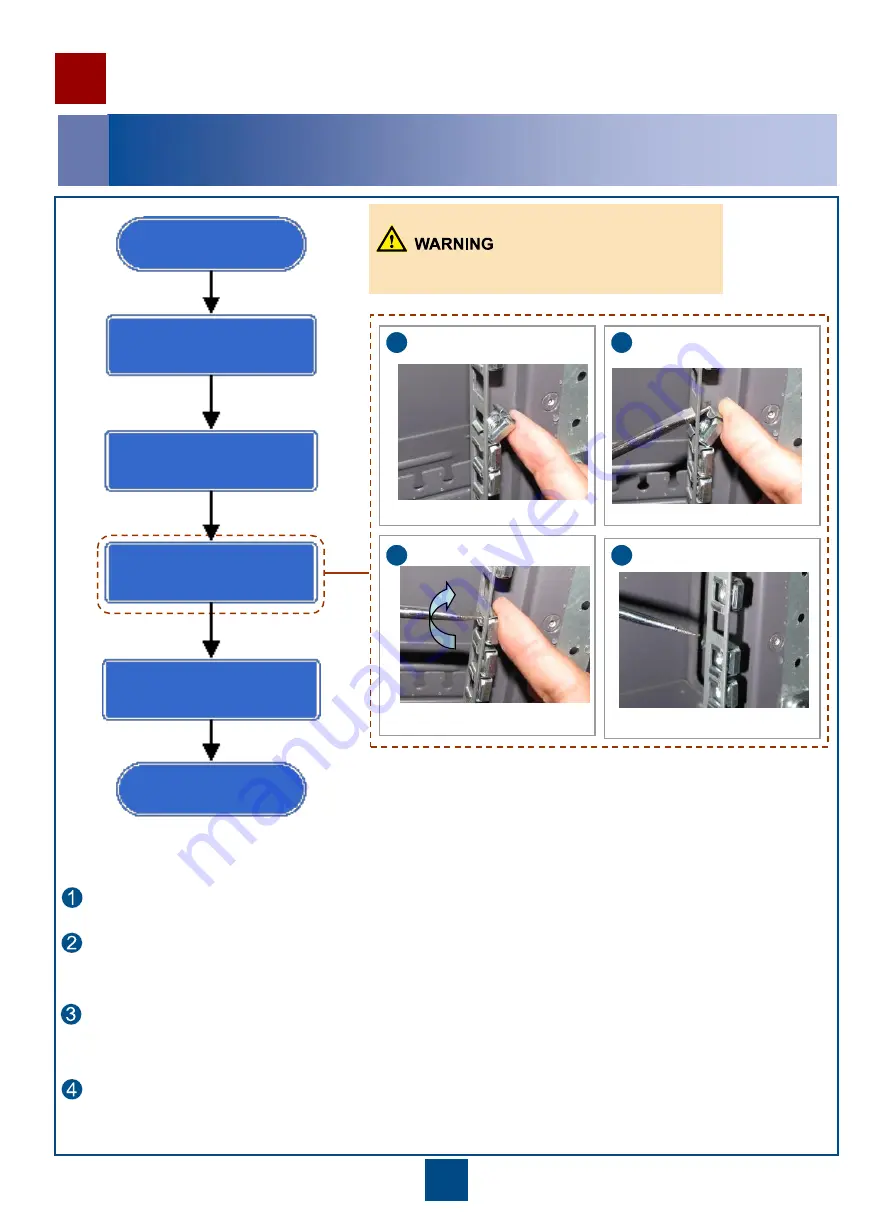
    Insert a flat-head screwdriver through the square hole and place the end of the screwdriver onto the upper tab 

of the captive nut. 

Installing the Components Inside the Cabinet 

Flowchart of installing the components inside the cabinet 


The procedure for installing the captive nut is as follows: 
 

 Insert the lower tab of the captive nut into the square hole and hold the captive nut in position. 

  Start 

Remove the filler panels 

Install captive nuts 

Install component 

End 

Determine the position  

    Use the screwdriver as a lever, and gently but firmly bend the upper tab of the captive nut downwards when 

pushing it through the square hole. 

    Remove the flat-head screwdriver to allow the upper tab to spring into position and release your hand. The 

assembly is complete. 

1


2


4


3


Take care not to stab fingers with screwdriver. 

Содержание eSight V200R003C00

Страница 1: ...HUAWEI TECHNOLOGIES Co Ltd Huawei eSight V200R003C00 Hardware Installation Guide N610E Issue 01 Date 2012 12 31 ...

Страница 2: ...dware Configuration Introduction to Devices Page 4 to 5 Page 6 Installing the Cabinet Installing the Signal Cables Installing Components Inside the Cabinet Installing the Power Cables Checking the Installation End Page 8 Page 9 to 10 Page 11 to 15 Page 16 to 22 Page 23 to 25 ...

Страница 3: ...n this document are written according to the standard configuration If the actual on site installation requirements are inconsistent with this document handle the requirements according to the actual situation Unless otherwise specified the slide rails installed in the cabinet are used for the corresponding devices The models of the corresponding floating nuts and panel screws are M6 Document Prep...

Страница 4: ...illips Screwdriver Flat head Screwdriver Torque Wrench Hydraulic Pliers COAX Crimping Tool Cable Cutter Wire Stripper Diagonal Pliers RJ45 Crimping Tool Multimeter Network Cable Tester ESD Gloves ESD Wrist Strap Socket Wrench 3 ...

Страница 5: ... X3650 M4 1 2U Power Distribution Box 3U LAN Switch 2 1U Filler panel 4U KVM Switch 1U Nonstandard Filler panel 1U Filler panel 4U Filler panel 2U Nonstandard Filler panel 1U Filler panel 2U Nonstandard Filler panel 1U Nonstandard Filler panel 1U Filler panel 2U Nonstandard Filler panel 1U Nonstandard Filler panel 1U Nonstandard Filler panel 1U Nonstandard Filler panel 1U Nonstandard Filler panel ...

Страница 6: ... Switch 1 1U X3850 X5 4 4U X3850 X5 3 4U KVM 1U X3850 X5 2 4U X3850 X5 1 4U Power Distribution Box 3U Filler panel 1U Filler panel 1U Cabling trough 1U Cabling trough 1U Filler panel 1U Filler panel 1U Filler panel 1U KVM Switch 1U Nonstandard filler panel 1U Nonstandard filler panel 1U Filler panel 1U Filler panel 1U Filler panel 2U Filler panel 1U Filler panel 3U Nonstandard filler panel 1U Nons...

Страница 7: ...ted manuals delivered with the equipment Component Height U Weight kg Power Consumption W Input Voltage V PC server IBM X3650 M4 2 30 750 100 to 132 200 to 240 PC server IBM X3850 X5 4 37 6 1440 100 to 132 200 to 240 Switch 1 3 30 100 to 240 KVM 1 13 56 90 to 264 If you install both IBM X3650 M4 and IBM X3850 X5 in the cabinet adjust their positions based on the configuration diagram and actual re...

Страница 8: ...ESD preventive wrist strap insert the wrist strap into the ESD plug of the cabinet You can clip the ESD preventive wrist strap with metallic clip to the cabinet directly Wearing an Antistatic Wrist Strap 1 Wearing Antistatic Clothes 2 Wearing Antistatic Gloves 3 Wearing an ESD preventive wrist strap plugged Scenario 2 ...

Страница 9: ...ion Guide V2 0 N610E 22 Cabinet Introduction to the N610E 22 cabinet N610E 22 cabinets are classified into single door cabinets and double door cabinets The left figure shows the appearance of a double door cabinet The appearance of an actually delivered cabinet may be different The N610E 22 cabinet complies with the requirement of the dimensions of mechanical structures of the 482 6 mm 19 inch se...

Страница 10: ... lower tab of the captive nut into the square hole and hold the captive nut in position 1 Start Remove the filler panels Install captive nuts Install component End Determine the position Use the screwdriver as a lever and gently but firmly bend the upper tab of the captive nut downwards when pushing it through the square hole Remove the flat head screwdriver to allow the upper tab to spring into p...

Страница 11: ...anel screws to fix the rear mounting point of the KVM to the square holes on both sides of the cabinet Use the panel screws to fix the front mounting point of the KVM to the square holes on both sides of the cabinet The PC server is heavy and two or three persons are required to carry the PC server 3 Determine the position in the cabinet for installing the PC server Remove the handle bar of the fr...

Страница 12: ...s of the KVM Switch 23 24 Power cables of the LAN Switch The Label No refers to the number printed on the cable label The Cable No refers to each cable number in the diagram The remaining cables that need not to be installed are bound in the applicable position of the cabinet and is delivered as the accessories APD B A output output input input LANS 2 X3650 M4 4 24 14 8642 23 13 7531 W1 KVM LANS 1...

Страница 13: ...of the LAN Switch The Label No refers to the number printed on the cable label The Cable No refers to each cable number in the diagram The remaining cables that need not to be installed are bound in the applicable position of the cabinet and is delivered as the accessories APD B A output output input input LANS 1 X3850 X5 3 1 2 4 3 12 15 13 14 12 6 4 2 19 10 5 31 11 18 9 W1 KVM LANS 0 19 18 X3850 ...

Страница 14: ... terminal block on the back provides dual AC inputs The terminal on each side supports the 220 V AC input The maximum current of each power input is 32 A The silkscreen on the top of the PDB describes the output current of the air breaker of group A B The preceding figure shows the dual input terminals of the APD32 6 24 AC PDB The four three pin connectors are connected to the following posts resp...

Страница 15: ...ut terminal block on the back supports dual AC inputs The terminal on each side allows one 220 V AC input The maximum current of each power input is 32 A The silkscreen on the top of the PDB describes the output current of the air breaker of group A B The preceding figure shows the dual input terminals of the APD32 6 24 AC PDB The four three pin connectors are connected to the following posts resp...

Страница 16: ...ists the specifications of the cables connected to the AC power distribution cabinet Function Electrical cable Dielectric strength 300 0 V Maximum current 36 A Type 227IEC10 BVV Color Black jacket cable core blue brown yellow green Cross sectional area 6 00 mm 2 Wire gauge Default Remarks 3 cores ...

Страница 17: ...evices The pictures in this document are referential to describe the installation procedure of the device If the pictures are different from the delivered devices take the delivered devices as the standard For details about the devices see the associated manuals delivered with the devices 1 Description of signal cables KVM rear view ...

Страница 18: ...f the pictures are different from the delivered devices take the delivered devices as the standard For details about the devices see the associated manuals delivered with the devices Description of signal cables Number IBM X3650M4 IBM X3850X5 1 IMM interface Ethernet interface 2 Ethernet interface IMM interface 3 VGA interface VGA interface IBM X3650M4 rear view 1 IBM X3850X5 rear view ...

Страница 19: ...VM controlling conversion cables 3 Connection relationships of the signal cables are marked after the commissioning of the device Labels are attached at both ends of a cable and the ports of the server Serial cable RJ 45 to DB 9 Introduction to cable labels ...

Страница 20: ...owing principle Connecting an Ethernet interface of the server and the switch by using a network cable 5 Cable connection of the X3850X5 server When connecting cables comply with the following principle Connecting an Ethernet interface of the server and the switch by using a network cable ...

Страница 21: ...he Keyboard Video and Mouse KVM is as follows Connecting the PS S interface of the KVM and the mouse keyboard and VGA interface of the server by using KVM conversion power cables KVM conversion cables a USB VGA PS 2 a b c The following figure shows the IBM X3650 M4 server a b c ...

Страница 22: ...21 Laying network cables 7 a Lay network cables inside the cabinet b Lay network cables underground between cabinets c Lay network cables overhead between cabinet ...

Страница 23: ...22 Laying optical fibers 8 a Lay optical fibers inside a cabinet b Lay optical fibers underground between cabinets c Lay optical fibers overhead between cabinets ...

Страница 24: ...dicate cabinet rows and columns are correctly attached 8 The ESD wrist strap is inserted into the ESD installation hole of the cabinet 9 All screws are fastened The flat washers and spring washers are mounted The spring washers are placed between the flat washers and the screws 10 The cabinets are stable and orderly 11 The vertical deviation of the cabinet is less than 3 mm 12 All cabinet side doo...

Страница 25: ...ls at the wiring terminals are tightly wrapped up with the insulating tape or heat shrinkable tubes 9 All screws are fastened The flat washers and spring washers are mounted The spring washers are placed between the flat washers and the screws 10 The power cables and PGND cables connecting the PDB with the functional modules and the PGND cables connecting the modules with the grounding bar are all...

Страница 26: ...s are coiled on the fiber management tray at the rear side of the cabinet 8 The signal cables connected to the left part of the subrack are led out of the subrack from the left Similarly the signal cables connected to the right part of the subrack are led out of the subrack from the right 9 The signal cables are bound separately from the power cables 10 The extra length of the cable ties must be c...

Страница 27: ...26 Changes in Documentation Issue 01 2012 12 31 This issue is the first official release ...

Страница 28: ...HUAWEI TECHNOLOGIES CO LTD Huawei Industrial Base Bantian Longgang Shenzhen 518129 People s Republic of China enterprise huawei com ...

Отзывы: