background image

5

NOTE

1.The optical connector connected to the 

OPTICAL

 port is an SC/APC connector, and the 

type of the optical connector connected to the optical port in the wall is determined by practical 

conditions.

2.To ensure normal use of fibers, make sure that the fiber bend radius is larger than 30 mm.

Step 2 Use a network cable to connect the 

LAN

 port to a PC or the Ethernet port on the 

IP STB.

Step 3 Use a phone line to connect the 

TEL

 port to a phone or fax machine. 

Step 4 Use a power adapter to connect the 

POWER

 port to the power socket.

The preceding figure connects the power adapter as an example. When connecting the 

backup battery unit , please see the usage guide to the backup battery for details .
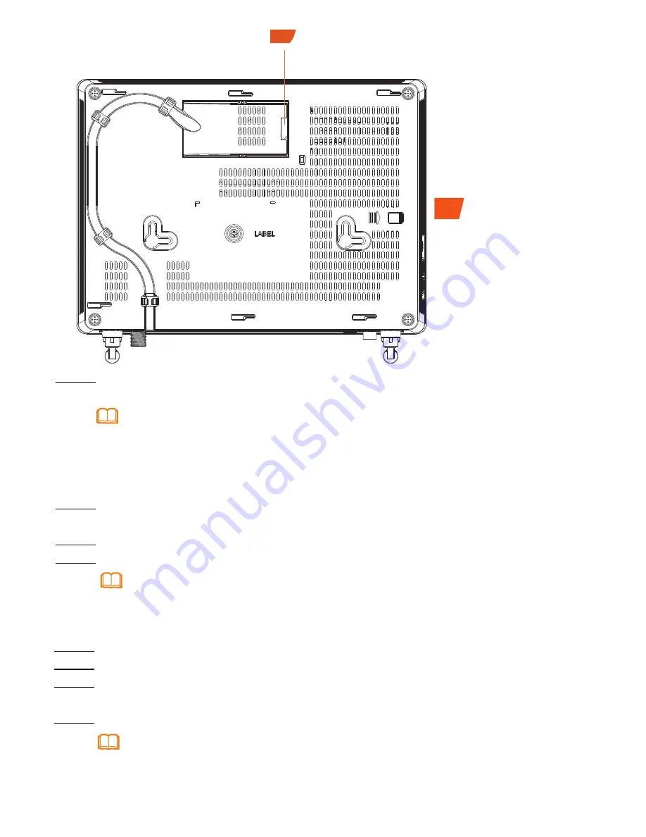
NOTE

Step 1 

Use an optical fiber to connect the optical port on the ONT and the optical port on 

the wall.The optical port of the HG8247H is at the back of the device. 

Step 5 Use a USB data cable to connect the 

USB

 port to the USB storage device. 

Step 6 Press the 

ON/OFF

 power switch.

Step 7 Press the 

WLAN

 switch to enable the Wi-Fi access function. By default, this 

function is enabled. 

Step 8 Press the 

WPS

 switch to enable the WPS encryption function. 

Before enabling the WPS encryption function of a GPON terminal, ensure that the function is 

set in the system software in advance. After successful setting, press the 

WPS

 switch for the 

settings to take effect.

NOTE

11

11

Optical port

Содержание EchoLife HG8247H

Страница 1: ...Quick Start EchoLife HG8247H GPON Terminal ...

Страница 2: ...ds of lightning activities The socket outlet shall be installed near the power adapter and shall be easily accessible Before use the power adapter please check no damage on the adapter Do not lead the strength member of the optical fiber or other metal parts indoors Do not install telephone lines network cables power adapters or power adapter cables outdoors Adopting these measures will help preve...

Страница 3: ...or be placed on a workbench Do not install GPON terminals in other modes such as the ceiling 3 The terminal cannot be connected to other devices such as GPON terminals switch and router Item Specifications Dimensions L x W x H 220 mm x 160 mm x 32 mm without an external antenna Weight including the power adapter About 800 g System power supply See the nameplate on the device Power adapter input 10...

Страница 4: ...wo mounting holes Step 2 Select a proper drill according to the outer diameter of the screws Use a hammer drill to drill the marked positions on the wall Then clean the wall and install two expansion bolts Step 3 Use a screwdriver to fasten the screws into the expansion bolts leaving the heads of the screws 3 mm over the wall Then install the GPON terminal to the screws ...

Страница 5: ...4 Connecting Cables 1 Power switch 2 Power port 3 USB port 4 POTS port 5 Ethernet port 6 Optical port 7 CATV port 8 Reset 9 WLAN switch WPS switch 10 ...

Страница 6: ... example When connecting the backup battery unit please see the usage guide to the backup battery for details NOTE Step 1 Use an optical fiber to connect the optical port on the ONT and the optical port on the wall The optical port of the HG8247H is at the back of the device Step 5 Use a USB data cable to connect the USB port to the USB storage device Step 6 Press the ON OFF power switch Step 7 Pr...

Страница 7: ...s One minute later it will be unlocked Change the initial password after logging in to the web page Step 1 Set the IP address of the PC in the same subnet as the management IP address of the GPON terminal Step 2 Enter the management IP address of the GPON terminal in the address bar of Internet Explorer and press Enter The login window is displayed Step 3 In the login window select your preferred ...

Страница 8: ...247H at a proper place to avoid walls or ceilings whenever possible 2 Observe the straight line rule when installing network devices The distance for which signals have to traverse at a 45 corner of two 0 5 meter thick walls reaches approximately one meter To better receive signals devices should be installed at places where signals can directly traverse walls or ceilings 3 Note the impact of buil...

Страница 9: ...n The USB port is connected and is working in the host mode but no data is transmitted Blinks twice a second Data is being transmitted on the USB port Off The system is not powered on or the USB port is not connected TEL1 TEL2 Steady on The terminal is registered with the softswitch but no service flows are transmitted Blinking Service flows are transmitted Off The terminal is not powered on or fa...

Страница 10: ...ireless network function press the WLAN button on the side panel of the HG8247H Indicator Description Table 2 Indicator status description 2 Status No Status Description PON LOS 1 Off Off The GPON terminal is prohibited by the upper layer device contact the service provider for help 2 Blinks twice a second Off The GPON terminal attempts to set up a connection with its upper layer device 3 Steady o...

Страница 11: ...nician for help This device complies with FCC radiation exposure limits set forth for an uncontrolled environment and it also complies with Part 15 of the FCC RF Rules This equipment must be installed and operated in accordance with provided instructions and the antenna s used for this transmitter must be installed to provide a separation distance of at least 20cm from all persons and must not be ...

Страница 12: ...p The phone does not ring upon an incoming call but communication is in normal state when the phone is in off hook state The GPON terminal provides a maximum of 60 V AC ringing current voltage Check whether the ringing current voltage of the phone is higher than 60 V AC If it is higher than 60 V AC replace it with another phone How to reset the GPON terminal Press Reset by using a needle type obje...

Страница 13: ..._____________________________ Purchase Date ______________________________________________________ Invoice Number ______________________________________________________ Dealer s Name ______________________________________________________ Dealer s Address _____________________________________________________ Dealer s Telephone ___________________________________________________ Warranty Card Thank ...

Страница 14: ...caused by the fact that the product is dismantled or altered by anyone that is not from a Huawei authorized service partner 3 The defects are caused by the fact that the product is used in a harsh environment that is not suitable for the operation of the product 4 The defects are caused by any force majeure including but not limited to fire earthquake lightning and tsunami 5 The defects are caused...

Страница 15: ...td Trademarks and Permissions and other Huawei trademarks are trademarks of Huawei Technologies Co Ltd All other trademarks and trade names mentioned in this document are the property of their respective holders Notice The information in this document is subject to change without notice Unless otherwise stated this guide serves only as a guide All statements information and recommendations in this...

Отзывы: