background image

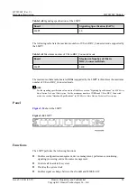
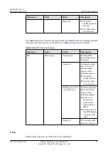
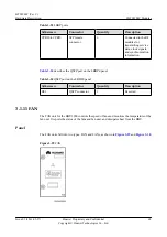
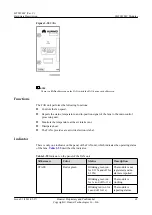
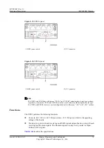
Figure 3-30

 FANc


NOTE

There is a 

FANc

 silkscreen on the FANc while the FAN has no such silkscreen.

Functions

The FAN unit performs the following functions:

l

Controls the fan speed.

l

Reports the status, temperature, and in-position signal of the fans to the main control
processing unit.

l

Monitors the temperature at the air intake vent.

l

Dissipates heat.

l

The FANc provides a read-write electronic label.

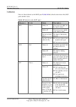
Indicator

There is only one indicator on the panel of the FAN unit, which indicates the operating status
of the fans. 

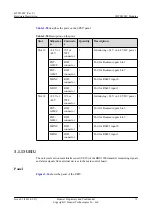
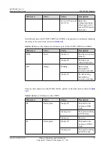
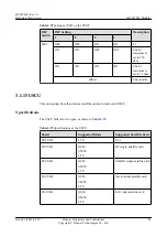
Table 3-55

 describes the indicator.

Table 3-55

 Indicator on the panel of the FAN unit

Silkscreen

Color

Status

Description

STATE

Red or green

Blinking green (on
for 0.125s and off for
0.125s)

The module is not
registered, and no
alarm is reported.

Blinking green (on
for 1s and off for 1s)

The module is
working.

Blinking red (on for
1s and off for 1s)

The module is
reporting alarms.

BTS3900C (Ver.C)
Hardware Description

3 BTS3900C Modules

Issue 03 (2013-05-27)

Huawei Proprietary and Confidential

Copyright © Huawei Technologies Co., Ltd.

69

Содержание BTS3900C

Страница 1: ...BTS3900C Ver C Hardware Description Issue 03 Date 2013 05 27 HUAWEI TECHNOLOGIES CO LTD ...

Страница 2: ... be within the purchase scope or the usage scope Unless otherwise specified in the contract all statements information and recommendations in this document are provided AS IS without warranties guarantees or representations of any kind either express or implied The information in this document is subject to change without notice Every effort has been made in the preparation of this document to ens...

Страница 3: ...00 Intended Audience This document is intended for l System engineers l Base station installation personnel l Site maintenance personnel Organization 1 Changes In BTS3900C Ver C Hardware Description This chapter describes the changes in the BTS3900C Ver C Hardware Description 2 BTS3900C Cabinet This chapter describes the exterior boards modules and configurations of the BTS3900C cabinets providing...

Страница 4: ... that may be found in this document are defined as follows Symbol Description Indicates a hazard with a high level or medium level of risk which if not avoided could result in death or serious injury Indicates a hazard with a low level of risk which if not avoided could result in minor or moderate injury Indicates a potentially hazardous situation that if not avoided could result in equipment dama...

Страница 5: ...al bars One item is selected or no item is selected x y Optional items are grouped in braces and separated by vertical bars A minimum of one item or a maximum of all items can be selected x y Optional items are grouped in brackets and separated by vertical bars Several items or no item can be selected GUI Conventions The GUI conventions that may be found in this document are defined as follows Con...

Страница 6: ...ions The mouse operations that may be found in this document are defined as follows Action Description Click Select and release the primary mouse button without moving the pointer Double click Press the primary mouse button twice continuously and quickly without moving the pointer Drag Press and hold the primary mouse button and move the pointer to a certain position BTS3900C Ver C Hardware Descri...

Страница 7: ...Assignment of the BBU3900 14 3 1 5 UMPT 28 3 1 6 WMPT 37 3 1 7 WBBP 43 3 1 8 GTMU 49 3 1 9 LMPT 57 3 1 10 LBBP 61 3 1 11 FAN 68 3 1 12 UPEU 70 3 1 13 UEIU 73 3 1 14 UTRP 74 3 1 15 USCU 83 3 1 16 UBRI 86 3 1 17 UELP 89 3 1 18 UFLP 90 3 2 RRU 92 3 3 GPS Surge Protector 92 4 BTS3900C Power System 94 4 1 Configurations of Upper Level Circuit Breakers and Power Cables 95 4 2 Power Distribution for the ...

Страница 8: ... 7 3 1 Power Cable Connections 130 7 3 2 Transmission Cable Connections 132 7 3 3 Monitoring Signal Cable Connections 141 7 3 4 CPRI Cable Connections 143 7 4 PGND Cables 146 7 5 Power Cables 147 7 5 1 DC Input Power Cable 147 7 5 2 AC Input Power Cable 148 7 5 3 ETP48100 A1 Power Cable 149 7 5 4 PDU10D 01 Power Cable 149 7 5 5 BBU Power Cable 150 7 5 6 HEUB Power Cable 151 7 5 7 RRU Power Cable 1...

Страница 9: ...nitoring Signal Cable 166 7 8 5 BBU Alarm Cable 167 7 8 6 ELU Signal Cable 169 7 8 7 Monitoring Signal Cable for the Door Status Sensor 170 7 8 8 Monitoring Signal Cable for the Surge Protection Box 170 7 8 9 GPS Clock Signal Cable 170 7 8 10 Adapter Used for Local Maintenance 171 7 9 RRU RF Jumper 172 7 10 RRU AISG Multi Wire Cable 172 7 11 RRU AISG Extension Cable 174 BTS3900C Ver C Hardware Des...

Страница 10: ... 7 7 CPRI Fiber Optic Cable Added information about the classification of CPRI fiber optic cables and the principles for selecting CPRI fiber optic cables 02 2012 12 30 This is the second official release Compared with issue 01 2012 11 10 no information is added from this issue Compared with issue 01 2012 11 10 this issue includes the following changes Topic Change Description All the sections Cha...

Страница 11: ...mpared with issue Draft A 2012 09 20 this issue includes the following changes Topic Change Description 3 1 5 UMPT Changed the indicator description of the UMPT Compared with issue Draft A 2012 09 20 no information is deleted from this issue Draft A 2012 09 20 This is a draft BTS3900C Ver C Hardware Description 1 Changes In BTS3900C Ver C Hardware Description Issue 03 2013 05 27 Huawei Proprietary...

Страница 12: ...Interior of the BTS3900C Cabinet This section describes the interior and configuration of the BTS3900C AC cabinet and BTS3900C DC cabinet 2 3 BTS3900C Engineering Specifications This section describes the BTS3900C engineering specifications The BTS3900C engineering specifications include input power specifications and equipment specifications BTS3900C Ver C Hardware Description 2 BTS3900C Cabinet ...

Страница 13: ...900C cabinet NOTE 1 OMB outdoor mini box 2 2 Interior of the BTS3900C Cabinet This section describes the interior and configuration of the BTS3900C AC cabinet and BTS3900C DC cabinet Interior of the BTS3900C AC Cabinet Figure 2 2 shows the interior of the BTS3900C AC cabinet and Table 2 1 describes the components in the BTS3900C AC cabinet BTS3900C Ver C Hardware Description 2 BTS3900C Cabinet Iss...

Страница 14: ...tion 1 ELU Mandatory 1 The electronic label unit ELU automatically reports the cabinet type 2 PMU 11A Mandatory 1 The power monitoring unit 11A PMU 11A manages the power system monitors power distribution and reports alarms BTS3900C Ver C Hardware Description 2 BTS3900C Cabinet Issue 03 2013 05 27 Huawei Proprietary and Confidential Copyright Huawei Technologies Co Ltd 5 ...

Страница 15: ...and power surge protection alarm information and reports the collected information to the BBU 4 PSU R4850G2 Mandatory 2 The power supply unit PSU converts 110 V AC or 220 V AC power into 48 V DC power 5 BBU3900 Mandatory 1 The BBU3900 is a baseband processing unit It processes the baseband signals of the base station BTS3900C Ver C Hardware Description 2 BTS3900C Cabinet Issue 03 2013 05 27 Huawei...

Страница 16: ...U10D 01 Mandatory 1 The power distribution unit 10D 01 PDU10D 01 provides 48 V DC power for all components in the cabinet 8 RRU subrack Mandatory 1 The RRU subrack houses the RRU 9 RRU Mandatory 1 The RRU processes and forwards RF signals between the BBU and antenna system 10 AC surge protection box Mandatory 1 The AC surge protection box provides surge protection for the input AC power BTS3900C V...

Страница 17: ...e BTS3900C DC cabinet and Table 2 2 describes the components in the BTS3900C DC cabinet Figure 2 3 Interior of the BTS3900C DC cabinet Table 2 2 Components in the BTS3900C DC cabinet No Component Optional Mandatory Maximum Quantity in a Single Cabinet Description 1 ELU Mandatory 1 The ELU automatically reports the cabinet type BTS3900C Ver C Hardware Description 2 BTS3900C Cabinet Issue 03 2013 05...

Страница 18: ... the BBU 3 BBU3900 Mandatory 1 The BBU3900 is a baseband processing unit It processes the baseband signals of the base station 4 Fan assembly Mandatory 2 The fan assembly dissipates heat from the cabinet including outer air circulation fan assembly and inner air circulation fan assembly Two fan assemblies are separately installed at the left bottom and the left top in the OMB BTS3900C Ver C Hardwa...

Страница 19: ...cifications Input Power Specifications The BTS3900C supports 110 V AC 220 V AC and 48 V DC power supply When AC power is used the base station converts AC power into 48 V DC power Table 2 3 and Table 2 4 list the input voltage scopes supported by the BTS3900C Table 2 3 AC input voltage range Input Power Rated Voltage Permissible Voltage Range 220 V AC single phase 200V AC to 240 V AC 176V AC to 29...

Страница 20: ...n x 16 54 in x 16 93 in Weight BTS3900C AC 32 kg without the BBU and RRU BTS3900C DC 25 kg without the BBU and RRU RRU subrack 4 kg without the RRU NOTE For details about other engineering specifications of the BTS3900C see 3900 Series Base Station Technical Description BTS3900C Ver C Hardware Description 2 BTS3900C Cabinet Issue 03 2013 05 27 Huawei Proprietary and Confidential Copyright Huawei T...

Страница 21: ...erms of their configuration rules functions ports indicators and DIP switches 3 2 RRU This section describes the types of RRUs supported by the BTS3900C 3 3 GPS Surge Protector The Global Positioning System GPS surge protector protects the satellite receiver from lightning BTS3900C Ver C Hardware Description 3 BTS3900C Modules Issue 03 2013 05 27 Huawei Proprietary and Confidential Copyright Huawe...

Страница 22: ...1 Figure 3 1 BBU3900 The Electronic Serial Number ESN is a unique identifier of a Network Element NE It is used during base station commissioning l If there is a label on the FAN unit of the BBU the ESN is printed on the label and a mounting ear of the BBU as shown in Figure 3 2 Figure 3 2 ESN 1 l If there is no label on the FAN unit of the BBU the ESN is printed on a mounting ear of the BBU as sh...

Страница 23: ...ort is used for commissioning the base station rather than importing or exporting the base station configuration 3 1 3 BBU3900 Technical Specifications This section describes the technical specifications of the BBU which include capacity transmission ports input power specifications equipment specifications environment specifications and surge protection specifications For details about technical ...

Страница 24: ...s 5 and 6 occupied FAN Mandatory 1 Slot 16 It is configured only in slot 16 UPEU Mandatory 2 Slot 18 or 19 A single UPEU is preferentially configured in slot 19 USCU Optional 1 Slot 0 or 1 It is preferentially configured in slot 1 The 1 U GPS GLONASS receiver is configured in slot 1 with slots 0 and 1 occupied UTRP Optional 1 Slot 0 or 4 It is preferentially configured in slot 4 UEIU Optional 1 Sl...

Страница 25: ... for the boards in the BBU3900 UMTS Table 3 2 Slot assignment principles for the boards in the BBU3900 UMTS Board Optional Mandatory Maximum Number Slot Restriction WMPT UMPT Mandatory 2 Slot 6 or 7 A single UMPT or WMPT is preferentially configured in slot 7 The UMPT and WMPT cannot be configured simultaneously BTS3900C Ver C Hardware Description 3 BTS3900C Modules Issue 03 2013 05 27 Huawei Prop...

Страница 26: ...d in descending order of priority in slot 3 0 1 2 4 or 5 The slot assignment principles for the WBBP boards are as follows l The WBBPd or WBBPf is preferentiall y configured in slot 3 or 2 The WBBPf takes precedence over the WBBPd in slot assignment l If five or more WBBPs are required ensure that a WBBP is installed in each of slots BTS3900C Ver C Hardware Description 3 BTS3900C Modules Issue 03 ...

Страница 27: ...lot 3 or 2 l If the WBBPf4 is installed in the same BBU as the WBBPf1 WBBPf2 and WBBPf3 the WBBPf4 is preferentiall y installed in slots 2 and 3 FAN Mandatory 1 Slot 16 It must be configured in slot 16 UPEU Mandatory 2 Slot 18 or 19 A single UPEU is preferentially configured in slot 19 UEIU Optional 1 Slot 18 BTS3900C Ver C Hardware Description 3 BTS3900C Modules Issue 03 2013 05 27 Huawei Proprie...

Страница 28: ...f them as following UTRPc UTRP6 UTRP9 UTRP2 UTRP3 UTRP4 USCU Optional 1 Slot 1 or 0 It is preferentially configured in slot 1 When configured with two satellite cards it is configured in slot 1 with both slots 0 and 1 occupied Figure 3 6 shows the typical configurations of the BBU3900 UMTS Figure 3 6 Typical configuration of the BBU3900 UMTS BTS3900C Ver C Hardware Description 3 BTS3900C Modules I...

Страница 29: ... LBBP Mandatory 6 Slots 0 to 5 A single LBBP is preferentially configured in slot 3 If more LBBPs are required the LBBP is installed in descending order of priority in slot 3 1 2 0 4 or 5 FAN Mandatory 1 Slot 16 It is configured only in slot 16 UPEU Mandatory 2 Slot 18 or 19 A single UPEU is preferentially configured in slot 19 UEIU Optional 1 Slot 18 UTRP Optional 1 Slot 4 or 5 It is preferential...

Страница 30: ...ly configured in slot 1 or a USCU that uses a dual satellite card is configured in slot 1 with both slots 1 and 0 occupied Figure 3 7 shows the typical configurations of the BBU3900 LTE Figure 3 7 Typical configuration of the BBU3900 LTE BBU3900 GU Table 3 4 describes the slot assignment principles for the boards in the BBU3900 GU BTS3900C Ver C Hardware Description 3 BTS3900C Modules Issue 03 201...

Страница 31: ... Slot 7 The WMPT or UMPT is configured only in slot 7 The UMPT and WMPT cannot be configured simultaneously GTMU Mandatory 1 Slots 5 and 6 It is configured only in slot 6 with slots 5 and 6 occupied BTS3900C Ver C Hardware Description 3 BTS3900C Modules Issue 03 2013 05 27 Huawei Proprietary and Confidential Copyright Huawei Technologies Co Ltd 22 ...

Страница 32: ...order of priority in slot 3 0 1 2 or 4 If a WBBPd or WBBPf is required it is installed in descending order of priority in slot 3 or 2 If five or more WBBPs are required ensure that a WBBP is installed in each of slots 2 and 3 At least one of the WBBPs in slots 2 and 3 is WBBPd or WBBPf The WBBPf takes precedence over the WBBPd during slot assignment BTS3900C Ver C Hardware Description 3 BTS3900C M...

Страница 33: ...kes precedence over the UTRP in UMTS mode during slot assignment USCU Optional 1 Slot 0 1 or 4 It is preferentially configured in slot 4 UBRI Optional 1 Slot 2 Figure 3 8 shows the typical configurations of the BBU3900 GU Figure 3 8 Typical configuration of the BBU3900 GU BBU3900 GL Table 3 5 describes the slot assignment principles for the boards in the BBU3900 GL BTS3900C Ver C Hardware Descript...

Страница 34: ...configured in slot 3 If more LBBPs are required the LBBP is installed in descending order of priority in slot 3 1 2 0 or 4 FAN Mandatory 1 Slot 16 It is configured only in slot 16 UPEU Mandatory 2 Slot 18 or 19 A single UPEU is preferentially configured in slot 19 UEIU Optional 1 Slot 18 UTRP Optional 2 Slot 0 or 4 It is preferentially configured in slot 4 The UTRP in GSM mode takes precedence ove...

Страница 35: ... Slot assignment principles for the boards in the BBU3900 UL Board Optional Mandatory Maximum Number Slot Restriction LMPT UMPT Mandatory 1 Slot 6 It is configured only in slot 6 WMPT UMPT Mandatory 1 Slot 7 It is configured only in slot 7 LBBP Mandatory 5 Slot 0 1 2 4 or 5 A single LBBP is configured only in slot 2 If more LBBPs are required the LBBP is installed in descending order of priority i...

Страница 36: ...m of six CPRI ports is configured in either slot 2 or slot 3 FAN Mandatory 1 Slot 16 It is configured only in slot 16 UPEU Mandatory 2 Slot 18 or 19 A single UPEU is preferentially configured in slot 19 UEIU Optional 1 Slot 18 UTRP Optional 2 Slot 4 or 5 It is preferentially configured in slot 4 The UTRP in UMTS mode takes precedence over the UTRP in LTE mode during slot assignment BTS3900C Ver C ...

Страница 37: ...C370 and later versions Specifications of the UMPT The UMPT is classified into four types UMPTa1 UMPTb1 UMPTa2 and UMPTa6 Table 3 7 lists the specifications of the UMPTa1 UMPTb1 UMPTa2 and UMPTa6 Table 3 7 Specifications of the UMPT Board Applicable Mode Transmissi on Mode Number of ports Port Capacity Full Half Duplex UMPTa1 UMPTb1 UMTS ATM over E1 T1 or IP over E1 T1 1 Four channels Transmissio ...

Страница 38: ...es the data radio bearer DRB specifications and maximum number of users supported by the UMPTa2 or UMPTa6 working in LTE mode Table 3 9 Data radio bearer specifications Board Maximum Number of Users UMPTa2 UMPTa6 10800 The maximum of data radio bearers DRBs supported by the UMPTa2 UMPTa6 working in LTE mode is three times the maximum number of UEs in RRC_Connected mode NOTE For the signaling speci...

Страница 39: ... 14 UMPTa6 Panel NOTE In the lower left of the UMPTa1 UMPTb1 UMPTa2 and UMPTa6 there are silkscreens UMPTa1 UMPTb1 UMPTa2 and UMPTa6 respectively indicating their board types Functions The UMPT performs the following functions BTS3900C Ver C Hardware Description 3 BTS3900C Modules Issue 03 2013 05 27 Huawei Proprietary and Confidential Copyright Huawei Technologies Co Ltd 30 ...

Страница 40: ...onnector A 10 Mbit s 100 Mbit s or 1000 Mbit s adaptive Ethernet electrical port is used for transmitting service data and signaling messages USB 1 USB connector The USB port with the USB silkscreen is used for the software upgrade of a base station using a USB flash driver This port also functions as a commissioning Ethernet port 2 The USB port with the CLK silkscreen functions as the TOD clock o...

Страница 41: ...ut the board is faulty Steady off There is no power supply or the board is faulty On for 1s and off for 1s The board is functioning properly On for 0 125s and off for 0 125s l The board is being loaded or configured l The board is not started ALM Red Steady on An alarm is generated and the board needs to be replaced Steady off The board is running properly On for 1s and off for 1s An alarm is gene...

Страница 42: ...he first 2s and then off for 2s l All cells corresponding to the subrack that houses this board are not activated l The S1 link is faulty NOTE Of UMPT boards only the UMPTa2 and UMPTa6 have this status Besides the preceding three indicators some other indicators indicate the connection status of the FE GE optical port FE GE electrical port interconnection port and E1 T1 port The indicators on the ...

Страница 43: ...n for the electrical port Green Steady on The connection is normal Steady off The connection is abnormal ACT silkscreen for the electrical port Orange Blinking Data is being transmitted Steady off No data is being transmitted CI Red or green Steady green The interconnection link is normal Steady red An optical module fails to receive signals because of one of the following reasons l The optical mo...

Страница 44: ... R2 Red or green Reserved L01 Red or green Steady off E1 T1 link 0 and 1 is not set up or an LOS alarm is generated Steady green E1 T1 links 0 and 1 are working properly Blinking green on for 1s and off for 1s E1 T1 link 0 is working properly but E1 T1 link 1 is not set up or an LOS alarm is generated Blinking green on for 0 125s and off for 0 125s E1 T1 link 1 is working properly but E1 T1 link 0...

Страница 45: ... an LOS alarm is generated Blinking green on for 0 125s and off for 0 125s E1 T1 link 3 is working properly but E1 T1 link 2 is not set up or an LOS alarm is generated Steady red Alarms are generated on E1 T1 links 2 and 3 Blinking red on for 1s and off for 1s An alarm is generated on E1 T1 link 2 Blinking red on for 0 125s and off for 0 125s An alarm is generated on E1 T1 link 3 DIP Switch Two DI...

Страница 46: ...W1 ON ON Reserved Reserved The E1 resistance is set to 75 ohms OFF ON The E1 resistance is set to 120 ohms ON OFF The T1 resistance is set to 100 ohms Table 3 14 DIP switch SW2 DIP Switch DIP Status Description 1 2 3 4 SW2 OFF OFF OFF OFF Balanced ON ON ON ON Unbalanced 3 1 6 WMPT The WCDMA main processing and transmission unit WMPT processes signals for the BBU3900 and manages resources for other...

Страница 47: ...7 shows the panel of the WMPT Figure 3 17 WMPT panel Functions The WMPT performs the following functions l Performs functions such as configuration management equipment management performance monitoring signaling processing and active and standby switchover and provides OM channel to communicate with the LMT or M2000 l Provides a reference clock for the system l Processes signaling and manages res...

Страница 48: ...or 0 125s l Data or software is being loaded to the board l The board is not started ALM Red Steady on An alarm is generated and the board must be replaced Steady off The board is running properly On for 1s and off for 1s An alarm is generated and you need to locate the fault before deciding whether to replace the board ACT Green Steady on The board serves as an active board Steady off l The board...

Страница 49: ...e WMPT panel whereas they are at both sides of the corresponding ports as shown in Figure 3 18 Figure 3 18 Port status indicators on the WMPT panel Table 3 17 describes the port status indicators on the WMPT panel Table 3 17 Port status indicators Indicator Color Status Description FE1 optical port status indicators Green LINK on the left side Steady on The connection is set up successfully Steady...

Страница 50: ...e Blinking Data is being transmitted or received Steady off No data is being transmitted or received Ports Table 3 18 describes the ports on the WMPT panel Table 3 18 Ports on the WMPT panel Silkscreen Connector Description E1 T1 port DB26 female connector E1 T1 port FE0 RJ45 connector FE electrical port FE1 SFP female connector FE optical port GPS SMA connector Reserved ETH 1 RJ45 connector Commi...

Страница 51: ... work mode of the E1 T1 signal cable and SW2 is used to set the resistance of the four E1 T1 signal cables in different modes Figure 3 19 shows the DIP switch settings of the WMPT Figure 3 19 DIP switch settings of the WMPT Table 3 19 and Table 3 20 list the DIP switch settings of the WMPT Table 3 19 Settings of the DIP switch SW1 on the WMPT DIP Switch DIP Status Description 1 2 3 4 SW1 ON ON OFF...

Страница 52: ...C320 and later versions Specifications The WBBP falls into four types as listed in Table 3 21 NOTE The WBBP in slot 2 or slot 3 could transfer the received CPRI data to other boards Table 3 21 Specifications of the WBBP Board Number of Cells Supported Number of UL CEs Number of DL CEs WBBPa 3 128 256 WBBPb1 3 64 64 WBBPb2 3 128 128 WBBPb3 6 256 256 WBBPb4 6 384 384 WBBPd1 6 192 192 WBBPd2 6 384 38...

Страница 53: ...144 96 WBBPd1 6x15 128 96 WBBPd2 6x15 144 144 WBBPd3 6x15 144 96 WBBPf1 6x15 144 144 WBBPf2 6x15 192 192 WBBPf3 6x15 256 256 WBBPf4 6x15 384 384 NOTE For the combined signaling specifications of the WBBP see section Signaling Specifications in 3900 Series Base Station Technical Description Panel The WBBP has four types of panels as shown in Figure 3 20 Figure 3 21 Figure 3 22 and Figure 3 23 Figur...

Страница 54: ...4 indicating their board types on the lower left corner of the board panel respectively Functions The WBBP performs the following functions l Provides CPRI ports for communication with RF modules and supports CPRI ports in 1 1 backup mode l Processes uplink and downlink baseband signals l The WBBPd supports interference cancellation IC within the board l When the WBBPd is installed in slot 2 or 3 ...

Страница 55: ...enerated and you need to locate the fault before deciding whether to replace the board ACT Green Steady on The board serves as an active board Steady off l The board does not serve as an active board l The board has not been activated l The board is not providing any services On for 1s and off for 1s The power supply for the board is insufficient NOTE Of all types of WBBP boards only the WBBPf has...

Страница 56: ... lock because of following reasons l There is no mutual lock between dual mode clock sources l There is mismatched data rate over CPRI ports l VSWR alarms are generated on the RF module connected to the CPRI link when the USB 1 flash drive is used for VSWR test Steady off l The optical module cannot be detected l The CPRI cable is not connected NOTE 1 The security of the USB port is ensured by enc...

Страница 57: ... because of the following reasons l The optical module is faulty l The fiber optic cable is broken Blinking red on for 1s and off for 1s The interconnection link is out of lock because of the following reasons l There is no mutual lock between two interconnected BBUs l There is mismatched data rate over QSFP ports Steady off The optical module cannot be detected Ports Table 3 26 describes the thre...

Страница 58: ...six CPRI ports and one HEI port as listed in Table 3 28 Table 3 28 Ports on the WBBPf panel Silkscreen Connector Description CPRIx SFP female connector Data transmission port interconnected to the RF module It supports the input and output of optical and electrical transmission signals HEI QSFP connector Port interconnected to other baseband boards to share the baseband resources 3 1 8 GTMU The GS...

Страница 59: ...0 Mbit s and 100 Mbit s Full duplex Transmissio n over FE electrical ports 1 10 Mbit s and 100 Mbit s Full duplex Table 3 30 lists the TRX specifications of the GTMU and GTMUb Table 3 30 TRX specifications of the GTMU Board Supported Mode Transmission Mode Maximum Carrier Number GTMU GTMUb GSM TDM 126 IP over FE 60 IP over E1 48 Panel Figure 3 24 and Figure 3 25 show the panels of the GTMU and GTM...

Страница 60: ...gnals l Provides CPRI ports for communication between the BBU and the RFUs Indicators Table 3 31 describes the indicators on the GTMU Table 3 31 Indicators on the GTMU Silkscreen Color Status Description RUN Green Steady on There is power supply but the board is faulty Steady off There is no power supply or the board is faulty On for 1s and off for 1s The board is running properly On for 0 125s an...

Страница 61: ...sponding ports and have no silkscreen Table 3 32 describes the indicators Table 3 32 Indicators for ports Indicator Color Status Description LIU0 to LIU3 Green Steady on An E1 T1 local alarm is generated On for 1s and off for 1s An E1 T1 remote alarm is generated Steady off The link is functional CPRI0 to CPRI5 Red or green Steady green The CPRI link is functioning properly Steady red An optical m...

Страница 62: ...or on the right side Blinking Data is being transmitted or received Steady off No data is being transmitted or received FE0 Green LINK indicator on the left side Steady on The connection is set up successfully Steady off No connection is set up Orange ACT indicator on the right side Blinking Data is being transmitted or received Steady off No data is being transmitted or received FE1 on the GTMUb ...

Страница 63: ...GTMUb SFP female connector Reserved ETH 1 RJ45 connector Local maintenance and commissioning port FE0 RJ45 connector Connected to the routers in the equipment room through FE cables to transmit network information FE1 DLC connector Connected to the routers in the equipment room through fiber optic cables to transmit network information TST 2 USB connector Providing reference clock for the test ins...

Страница 64: ...four bits DIP switches S1 and S2 need to be set jointly The functions of the five DIP switches are as follows l S1 is used to select the E1 resistance Table 3 35 provides details on the DIP switch l S2 is used to select the grounding mode of E1 T1 transmission cables Table 3 36 provides details on the DIP switch l S3 is reserved l S4 is used to select the E1 bypass Table 3 37 provides details on t...

Страница 65: ...75 ohm all the bits of S2 must be set to ON to rectify the faults on the E1 links Others Unavailable Table 3 37 Description on S4 DIP Switch DIP Setting Description 1 2 3 4 S4 ON ON ON ON Supporting E1 bypass OFF OFF OFF OFF Not supporting E1 bypass Others Unavailable Table 3 38 Description on S5 DIP Switch DIP Setting Description 1 2 3 4 S5 ON ON ON ON Not supporting E1 bypass OFF ON ON OFF Suppo...

Страница 66: ... and provides system clock for the BBU3900 Specifications Table 3 39 lists the specifications of the LMPT Table 3 39 Specifications of the LMPT Board Mode Transmissi on Mode Number of ports Port Capacity Full Half Duplex LMPT LTE Transmissio n over FE GE optical ports 2 10 Mbit s 100 Mbit s and 1000 Mbit s Full duplex Transmissio n over FE GE electrical ports 2 10 Mbit s 100 Mbit s and 1000 Mbit s...

Страница 67: ...ecifications in 3900 Series Base Station Technical Description For the maximum number of DRBs and UEs in RRC_Connected mode see section Baseband Specifications in 3900 Series Base Station Technical Description Panel Figure 3 26 shows the LMPT Figure 3 26 LMPT Functions The LMPT performs the following functions l Enables configuration management device management performance monitoring signaling pr...

Страница 68: ...dy off The board is running properly On for 1s and off for 1s An alarm is generated and you need to locate the fault before deciding whether to replace the board ACT Green Steady on The board serves as an active board Steady off l The board does not serve as an active board l The board has not been activated l The board is not providing any services On for 0 125s and off for 0 125s The OML is disc...

Страница 69: ... Steady off No data is being transmitted or received ETH Orange ACT Blinking Data is being transmitted or received Steady off No data is being transmitted or received Green LINK Steady on The connection is set up successfully Steady off No connection is set up FE GE0 to FE GE1 Green LINK Steady on The connection is set up successfully Steady off No connection is set up Orange ACT Blinking Data is ...

Страница 70: ...g the base station through the OM port 2 The TST port is used for commissioning the base station rather than importing or exporting the base station configuration 3 The security of the USB port is ensured by encryption NOTE SFP0 and FE GE0 ports on the LMPT are used for one GE input Therefore they are not used simultaneously SFP1 and FE GE1 ports on the LMPT are used for another GE input Therefore...

Страница 71: ... data radio bearers DRBs supported by the LBBP is three times the maximum RRC_connected users NOTE For the signaling specifications of an entire eNodeB see section Signaling Specifications in 3900 Series Base Station Technical Description For the following specifications see section Baseband Specifications in 3900 Series Base Station Technical Description the maximum number of data radio bearers m...

Страница 72: ... Cell Bandwidth Antenna Configuration LBBPc 3 1 4 MHz 3 MHz 5 MHz 10 MHz 15 MHz and 20 MHz 3x20 MHz 1T1R 3x20 MHz 1T2R 3x10 MHz 4T4R 3x20 MHz 2T2R 1x20 MHz 4T4R LBBPd1 3 1 4 MHz 3 MHz 5 MHz 10 MHz 15 MHz and 20 MHz 3x20 MHz 1T1R 3x20 MHz 1T2R 3x20 MHz 2T2R LBBPd2 3 1 4 MHz 3 MHz 5 MHz 10 MHz 15 MHz and 20 MHz 3x20 MHz 1T1R 3x20 MHz 1T2R 3x20 MHz 2T2R 3x20 MHz 4T4R LBBPd3 6 1 4 MHz 3 MHz 5 MHz 10 M...

Страница 73: ...ee cells connected to the LBBPc can use any of the following antenna configurations 1 4 MHz 2T2R 3 MHz 2T2R 5 MHz 2T2R 10 MHz 2T2R 15 MHz 2T2R and 20 MHz 2T2R l The LBBP supports CPRI convergence when the site is configured with any of the following RRUs RRU3221 RRU3240 RRU3828 RRU3829 RRU3928 RRU3929 LRFUe MRFUd RRU3229 RRU3841 RRU3942 RRU3642 RRU3832 RRU3838 and RRU3268 The CPRI convergence of t...

Страница 74: ...ady on There is power supply but the board is faulty Steady off There is no power supply or the board is faulty On for 1s and off for 1s The board is functioning properly On for 0 125s and off for 0 125s l The board is being loaded or configured l The board is not started ALM Red Steady on An alarm is generated and the board must be replaced Steady off The board is running properly On for 1s and o...

Страница 75: ...tus Description CPRIx Red or green Steady green The CPRI link is functioning properly Steady red An optical module fails to receive or transmit signals because of the following reasons l The optical module is faulty l The fiber optic cable is broken Blinking red on for 0 125s and off for 0 125s The RF module connected to the CPRI link has a hardware fault Blinking red on for 1s and off for 1s The ...

Страница 76: ...y red An optical module fails to receive or transmit signals because of the following reasons l The optical module is faulty l The fiber optic cable is broken Blinking red on for 1s and off for 1s The interconnection link is out of lock because of the following reasons l There is no mutual lock between two interconnected BBUs l The data rates of the QSFP ports do not match each other Steady off Th...

Страница 77: ...Connector Quantity Description HEI QSFP connector 1 Reserved 3 1 11 FAN The FAN unit for the BBU3900 controls the speed of fans and monitors the temperature of the fan unit It reports the status of the fans and fan unit and dissipates heat from the BBU Panel The FAN units fall into two types FAN and FANc as shown in Figure 3 29 and Figure 3 30 Figure 3 29 FAN BTS3900C Ver C Hardware Description 3 ...

Страница 78: ... only one indicator on the panel of the FAN unit which indicates the operating status of the fans Table 3 55 describes the indicator Table 3 55 Indicator on the panel of the FAN unit Silkscreen Color Status Description STATE Red or green Blinking green on for 0 125s and off for 0 125s The module is not registered and no alarm is reported Blinking green on for 1s and off for 1s The module is workin...

Страница 79: ...ent interface unit type c UPEUc and universal power and environment interface unit type d UPEUd The UPEUa UPEUc and UPEUd convert 48 V DC power into 12 V DC power and the UPEUb converts 24 V DC power into 12 V DC power Figure 3 31 Figure 3 32 Figure 3 33 and Figure 3 34 show the panels of the UPEUa UPEUb UPEUc and UPEUd respectively Figure 3 31 UPEUa panel 1 BBU power switch 2 7W2 connector Figure...

Страница 80: ...silkscreens 48 V and 24 V on them Functions The UPEU performs the following functions l Converts 48 V DC or 24 V DC power into 12 V DC power which is the operating voltage of the boards l Provides two ports with each receiving one RS485 signal and another two ports with each receiving four Boolean signals The Boolean signals can only be dry contact or Open Collector OC signals Table 3 56 describes...

Страница 81: ...r consumption shown in the M2000 after the UPEUa is replaced by the UPEUc does not necessarily reflect the actual decrease of power consumption Indicator The UPEU has one indicator which indicates the operating status of the UPEU Table 3 57 describes the indicator Table 3 57 Indicator on the UPEU panel Silkscreen Color Status Description RUN Green Steady on The board is functional Steady off There...

Страница 82: ...r 48 V 3V3 or 7W2 connector 1 Introducing 24 V or 48 V DC power EXT ALM0 RJ45 connector 1 Port for Boolean inputs 0 to 3 EXT ALM1 RJ45 connector 1 Port for Boolean inputs 4 to 7 MON0 RJ45 connector 1 Port for RS485 input 0 MON1 RJ45 connector 1 Port for RS485 input 1 3 1 13 UEIU The universal environment interface unit UEIU of the BBU3900 transmits monitoring signals and alarm signals from externa...

Страница 83: ...each transmitting four paths of Boolean signals Table 3 59 describes the ports on the panel of the UEIU Table 3 59 Ports on the panel of the UEIU Slot Silkscre en Connect or Quanti ty Description Slot 18 EXT ALM0 RJ45 connector 1 Port for Boolean inputs 0 to 3 EXT ALM1 RJ45 connector 1 Port for Boolean inputs 4 to 7 MON0 RJ45 connector 1 Port for RS485 input 0 MON1 RJ45 connector 1 Port for RS485 ...

Страница 84: ...Pb4 Without a sub board GSM TDM over E1 T1 2 Eight channels Full duplex UTRP6 UUAS UMTS STM 1 OC 3 1 One channel Full duplex UTRP9 UQEC UMTS Transmiss ion over FE GE electrical ports 4 10 Mbit s 100 Mbit s and 1000 Mbit s Full duplex UTRPc Without a sub board GSM UMTS LTE Transmiss ion over FE GE electrical ports 4 10 Mbit s 100 Mbit s and 1000 Mbit s Full duplex Transmiss ion over FE GE optical p...

Страница 85: ... in GSM mode Figure 3 39 Panel of the UTRP4 with eight E1 T1 channels Figure 3 40 shows the panel of the UTRP6 Figure 3 40 Panel of the UTRP6 with one STM 1 channel Figure 3 41 shows the panel of the UTRP9 Figure 3 41 Panel of the UTRP9 with four electrical ports BTS3900C Ver C Hardware Description 3 BTS3900C Modules Issue 03 2013 05 27 Huawei Proprietary and Confidential Copyright Huawei Technolo...

Страница 86: ...Ua cannot be used together with the UTRPc Indicators Table 3 61 describes the indicators on the UTRP panel Table 3 61 Indicators on the UTRP panel Silkscreen Color Status Description RUN Green Steady on There is power supply but the board is faulty Steady off There is no power supply or the board is faulty On for 1s and off for 1s The board is running properly On for 0 125s and off for 0 125s l Th...

Страница 87: ... not been activated l The board is not providing any services The ACT indicator on the UTRP board in GSM mode has different status from the ACT indicator on other boards as listed in Table 3 62 Table 3 62 Status of the ACT indicator on the UTRP board in GSM mode Silkscreen Color Status Description ACT Green Steady on l Before the configuration takes effect none or both of the two E1 ports in GSM m...

Страница 88: ...erly ACT Orange Blinking Data is being transmitted or received on the link Steady off No data is being transmitted or received on the link There are three indicators on the UTRPc R0 R1 and R2 of which the status is listed in Table 3 64 Table 3 64 Status of indicators on the UTRPc Silkscreen Color Status Description R0 Red or green Steady off The board is not working in GSM mode Steady green The bo...

Страница 89: ...E optical port 2 SFP female connector The UTRP3 UTRP4 and UTRPb4 have the same ports as listed in Table 3 66 Table 3 66 Ports on the panel of the UTRP3 UTRP4 and UTRPb4 with 8 E1 T1 ports Silkscreen Port Type Quantity Connector E1 T1 E1 T1 port 2 DB26 female connector Table 3 67 lists the ports on the UTRP6 Table 3 67 Ports on the panel of the UTRP6 with one STM 1 channel Silkscreen Port Type Quan...

Страница 90: ...FE GE2 to FE GE5 FE GE electrical port 4 RJ45 connector DIP Switch There is no DIP switch on the UTRP2 UTRP6 and UTRP9 There are three DIP switches on the UTRP3 UTRP4 and UTRPb4 SW1 and SW2 are used to set whether to ground the receiver end of the E1 cable and SW3 is used to set the resistance of the E1 cable Figure 3 43 shows the DIP switches on the UTRP3 and UTRP4 Figure 3 44 shows the DIP switc...

Страница 91: ...ed Others Unavailable Table 3 71 Settings of SW2 on the UTRP DIP Switch DIP Setting Description 1 2 3 4 SW2 OFF OFF OFF OFF Balanced ON ON ON ON Imbalanced Others Unavailable CAUTION SW1 and SW2 are set to OFF by default SW1 corresponds to No 4 to No 7 E1 channels SW2 corresponds to No 0 to No 3 E1 channels BTS3900C Ver C Hardware Description 3 BTS3900C Modules Issue 03 2013 05 27 Huawei Proprieta...

Страница 92: ...ecifications The USCU falls into five types as shown in Table 3 73 Table 3 73 Specifications of the USCU Board Supported Mode Supported Satellite Card USCUb11 LTE N A USCUb12 GSM UMTS LTE RT single satellite card USCUb14 GSM UMTS LTE UBLOX single satellite card USCUb22 GSM UMTS LTE Naviors dual satellite card USCUb21 GSM UMTS LTE K161 dual satellite card BTS3900C Ver C Hardware Description 3 BTS39...

Страница 93: ...on the lower left corner of the board panel respectively Functions The USCU has the following functions l The USCUb11 provides ports to communicate with the RGPS for example the reused equipment of the customer and BITS equipment It does not support GPS signals l The USCUb12 contains an RT satelliate card which does not support RGPS signals l The USCUb14 contains a UBLOX satelliate card which does...

Страница 94: ...The board is not started ALM Red Steady on An alarm is generated and the board needs to be replaced Steady off The board is running properly On for 1s and off for 1s An alarm is generated and you need to locate the fault before deciding whether to replace the board ACT Green Steady on The board serves as an active board Steady off l The board does not serve as an active board l The board has not b...

Страница 95: ... signals The RGPS ports on the USCUb12 USCUb21 USCUb14 and USCUb22 are reserved and cannot receive RGPS signals TOD0 port RJ45 connector This port receives or transmits 1PPS TOD signals TOD1 port RJ45 connector This port receives or transmits 1PPS TOD signals and receives TOD signals from the M1000 BITS port SMA connector This port receives BITS clock signals supports adaptive input of 2 048 MHz a...

Страница 96: ...1s and off for 1s The board is running properly On for 0 125s and off for 0 125s Software is being loaded to the board ALM Red Steady on An alarm is generated on the board Steady off The board is running properly On for 1s and off for 1s An alarm is generated and you need to locate the fault before deciding whether to replace the board ACT Green Steady on The board serves as an active board Steady...

Страница 97: ...RI link is out of lock because of the following reasons l There is no mutual lock between dual mode clock sources l The data rates of the CPRI ports do not match each other Steady off l The optical module cannot be detected l The CPRI cable is not connected Ports Table 3 79 describes the ports on the UBRI panel Table 3 79 Ports on the UBRI panel Silkscreen Connector Quantity Description CPRI0 to C...

Страница 98: ...sts the ports on the UELP Table 3 81 Ports on the UELP Silkscreen Connector Description INSIDE DB25 female connector Connecting to a transmission board of the base station OUTSIDE DB26 female connector Connecting to an external transmission device DIP Switch The UELP has one DIP switch which is used to determine whether the receiving end is grounded The DIP switch has four DIP bits Figure 3 49 sho...

Страница 99: ...E1 cable of 120 ohms and the T1 cable of 100 ohms cannot be grounded 3 1 18 UFLP Each universal FE lightning protection unit UFLP provides protection for two channels of FE signals Each universal FE lightning protection unit type B UFLPB provides protection for two channels of FE GE signals NOTE The UFLPB applies only to the LTE mode BTS3900C Ver C Hardware Description 3 BTS3900C Modules Issue 03 ...

Страница 100: ...smission board of the base station OUTSIDE side FE0 and FE1 RJ45 connector Connecting to an external transmission device Table 3 84 describes UFLPB ports Table 3 84 UFLPB ports Port Location Silkscreen on the Panel Connector Description INSIDE side FE GE0 and FE GE1 RJ45 connector Connecting to a transmission board of the base station BTS3900C Ver C Hardware Description 3 BTS3900C Modules Issue 03...

Страница 101: ...nd TX signals which enables these signals to share the same antenna path It also filters the RX and TX signals l For the RRUs with a built in Bias Tee BT the built in BT couples RF signals and OOK signals and transmits them through the TX RX port A The built in BT also supplies power to the tower mounted amplifier TMA Table 3 85 lists the types of RRUs supported by the BTS3900C For details about t...

Страница 102: ...the GPS surge protector Table 3 86 Ports on the GPS surge protector SN Silkscreen Connector 1 Surge N type female connector 2 Ground terminal 3 Protect N type male connector BTS3900C Ver C Hardware Description 3 BTS3900C Modules Issue 03 2013 05 27 Huawei Proprietary and Confidential Copyright Huawei Technologies Co Ltd 93 ...

Страница 103: ...n for the BTS3900C This section describes power distribution schemes for BTS3900C cabinets when 110 V AC 220 V AC or 48 V DC power is supplied 4 3 ETP48100 A1 The embedded telecommunication power 48100 A1 ETP48100 A1 system converts external 220 V or 110 V AC input power into 48 V DC power 4 4 PDU10D 01 The power distribution unit 10D 01 PDU10D 01 distributes 48 V DC power to all components in the...

Страница 104: ...0 025 in 2 15 m 110 V AC dual live wire 20 A 2 P NOTE 1 P is short for Pole indicating the number of switches simultaneously controlled by a pole Table 4 2 lists the recommended configurations of upper level circuit breakers and power cables for a BTS3900C DC cabinet Table 4 2 Recommended configurations of upper level circuit breakers and power cables for a BTS3900C DC cabinet Input Power Requirem...

Страница 105: ...ble 4 3 Specifications of fuses when 110 V AC or 220 V AC power is supplied Input Power Specifications of a circuit breaker 220 V AC single phase l RRU 1x30 A l BBU 1x30 A l HEUB 1x30 A 110 V AC dual live wire Power Distribution Scheme in the 48 V DC Power Supply Scenario When 48 V DC power is supplied the PDU10D in the OMB converts the one DC input into several DC outputs and distributes the DC p...

Страница 106: ...ower 48100 A1 ETP48100 A1 system converts external 220 V or 110 V AC input power into 48 V DC power 4 3 1 ETP48100 A1 Components The embedded telecommunication power 48100 A1 ETP48100 A1 system consists of the power monitoring unit 11A PMU 11A power supply unit PSU and ETP48100 A1 subrack Figure 4 3 shows the ETP48100 A1 components BTS3900C Ver C Hardware Description 4 BTS3900C Power System Issue ...

Страница 107: ...0 A1 subrack Figure 4 4 ETP48100 A1 subrack 1 AC input terminal 2 Circuit breaker 3 DC output terminal Table 4 5 describes the ports on an ETP48100 A1 subrack Table 4 5 Ports on an ETP48100 A1 subrack Port Silkscreen Connector AC input terminal INPUT OT terminal Circuit breaker LOAD0 LOAD1 DC output terminal OUTPUT OT terminal BTS3900C Ver C Hardware Description 4 BTS3900C Power System Issue 03 20...

Страница 108: ...ms the following functions l Manages the power system l Reports the battery temperature l Monitors power distribution and reports alarms Ports Figure 4 6 shows the ports on the PMU 11A and Table 4 6 describes these ports Figure 4 6 Ports on the PMU 11A BTS3900C Ver C Hardware Description 4 BTS3900C Power System Issue 03 2013 05 27 Huawei Proprietary and Confidential Copyright Huawei Technologies C...

Страница 109: ...en Color Description Status Description RUN Green Running status indicator Steady on The PMU 11A is performing startup self check loading and activation Blinking on for 1s and off for 1s The PMU 11A is functional and communicating with the BBU properly This status does not necessarily mean that the PMU 11A has been configured Blinking on for 0 125s and off for 0 125s The PMU 11A is functional but ...

Страница 110: ... Four least significan t bits 1 2 3 and 4 Define the monitoring address of the PMU The bit 1 indicates ON and the bit 0 indicates OFF Bits 1 to 4 are set to 1100 by default before delivery Four most significan t bits 5 6 7 and 8 Reserved for future use The bit 1 indicates ON and the bit 0 indicates OFF Bits 5 to 8 are set to 0000 by default before delivery 4 3 4 PSU The power supply unit PSU conve...

Страница 111: ...exterior NOTE A scanner is required for stock management to scan the two dimensional bar code on the front panel of the PSU Indicators Figure 4 9 shows the indicators on the front panel of the PSU Figure 4 9 Indicators on the front panel of the PSU 1 Power indicator 2 Protection indicator 3 Fault indicator Table 4 9 describes the indicators on the front panel of the PSU BTS3900C Ver C Hardware Des...

Страница 112: ...f for 1s The communication between the PSU and the PMU is interrupted Fault indicato r Red Steady off The PSU is functioning properly Steady on The PSU is faulty or shut down in case of an emergency Diagnose the fault to determine whether to replace the PSU 4 4 PDU10D 01 The power distribution unit 10D 01 PDU10D 01 distributes 48 V DC power to all components in the cabinet Exterior Figure 4 10 sho...

Страница 113: ... 11 Ports on the PDU10D 01 Table 4 10 Ports on the PDU10D 01 No Port Silkscreen Matched Terminal and Cable Description 1 DC input terminals NEG One hole OT terminal M6 The maximum cross sectional area of the cable supported is 25 mm2 0 039 in 2 for one input or 16 mm2 0 025 in 2 for two inputs Negative power input wiring terminal RTN Positive power input wiring terminal BTS3900C Ver C Hardware Des...

Страница 114: ...o any one among ports LOAD6 to LOAD9 The maximum cross sectional area of the cable is 4 mm2 0 006 in 2 NOTE Figure 4 13 shows an EPC4 or EPC6 connector An EPC4 connector must be connected to a cable onsite whereas an EPC6 connector has been connected to a cable before delivery The EPC5 connector must be connected to the cable onsite The output current is 30 A 5 Spare fuse box There are three fuses...

Страница 115: ...otection for the input AC power Exterior Figure 4 14 shows the panel of an AC surge protection box Figure 4 14 Panel of the AC surge protection box 1 AC surge protection box 2 Alarm port 3 AC power supply ports BTS3900C Ver C Hardware Description 4 BTS3900C Power System Issue 03 2013 05 27 Huawei Proprietary and Confidential Copyright Huawei Technologies Co Ltd 106 ...

Страница 116: ...Silkscreen Connector Description Port for alarm reporting ALARM Bare wire Port for collecting the AC input surge protection alarm AC power supply port L Cord end terminal AC power supply port N PE BTS3900C Ver C Hardware Description 4 BTS3900C Power System Issue 03 2013 05 27 Huawei Proprietary and Confidential Copyright Huawei Technologies Co Ltd 107 ...

Страница 117: ...ious boards The boards collect alarms from sensors and fans and then transmit the alarm signals to the MON port on the BBU through the RS485 serial bus In this manner the boards monitor the cabinet 5 2 BBU Monitoring Port The BBU houses the UPEU and UEIU for monitoring Each board has two Boolean input ports and two RS485 input ports and each Boolean input port receives four Boolean inputs 5 3 Moni...

Страница 118: ...r monitoring of a BTS3900C cabinet when the BBU is installed in the OMB Principles for Monitoring a BTS3900C Cabinet in the 48 V DC Power Supply Scenario Figure 5 2 illustrates the principles for monitoring a BTS3900C cabinet when the BBU is installed in the OMB For details about modules monitored by the HEUB see 5 3 1 HEUB Figure 5 2 Principles for monitoring of a BTS3900C cabinet when the BBU is...

Страница 119: ... 7 MON0 RJ45 connector 1 Port for RS485 input 0 MON1 RJ45 connector 1 Port for RS485 input 1 Slot18 UEIU optional EXT ALM0 RJ45 connector 1 Port for Boolean inputs 0 to 3 EXT ALM1 RJ45 connector 1 Port for Boolean inputs 4 to 7 MON0 RJ45 connector 1 Port for RS485 input 0 MON1 RJ45 connector 1 Port for RS485 input 1 5 3 Monitoring Boards This section describes monitoring boards in a BTS3900C cabin...

Страница 120: ...ons The HEUB performs the following functions l Provides 48 V DC power to the fan assembly l Collects the cabinet environment monitoring information l Collects the surge protection alarm information of power equipment when AC power is used l Monitors the running status of fans and supports fan speed adjustment based on temperature or controlled by the BBU l Reports collected information to the BBU...

Страница 121: ...ection alarm GATE Bare wire Port for the door status sensor COM_IN RJ45 connector Port for reporting monitoring signals COM_OUT RJ45 connector Port connected to the ETP48100 A1 PWR 3V3 power connector 48 V DC input port 5 3 2 PMU 11A The power monitoring unit 11A PMU 11A manages the power system monitors power distribution and reports alarms Exterior Figure 5 5 shows a PMU 11A Figure 5 5 PMU 11A B...

Страница 122: ...or Connects to a door status sensor 2 TEM_BAT 2 pin connector Reserved for a battery temperature sensor 3 COM_IN RJ45 connector Connects to the BBU or upper level device and reports alarms to the BBU 4 COM_OUT RJ45 connector Connects to the BBU or lower level devices and collects alarms from lower level devices 5 COM_485 RJ45 connector Reserved Indicators Table 5 4 describes the indicators on the ...

Страница 123: ... unable to communicate with the PMU properly Steady off The PMU is faulty or there is no DC power supply ALM Red Alarm indicator Steady on An alarm is generated Steady off No alarms is generated Blinking on for 1s and off for 1s An alarm is generated and you need to locate the fault before deciding whether to replace the PMU 11A DIP Switch Figure 5 7 shows the DIP switches on the PMU 11A Figure 5 ...

Страница 124: ...es OFF Bits 1 to 4 are set to 1100 by default before delivery Four most significan t bits 5 6 7 and 8 Reserved for future use The bit 1 indicates ON and the bit 0 indicates OFF Bits 5 to 8 are set to 0000 by default before delivery BTS3900C Ver C Hardware Description 5 BTS3900C Monitoring System Issue 03 2013 05 27 Huawei Proprietary and Confidential Copyright Huawei Technologies Co Ltd 115 ...

Страница 125: ... cabinet 6 2 ELU The electronic label unit ELU reports the cabinet type automatically to facilitate troubleshooting 6 3 BTS3900C Sensors The BTS3900C sensors consist of the door status sensor and temperature sensor BTS3900C Ver C Hardware Description 6 BTS3900C Components Issue 03 2013 05 27 Huawei Proprietary and Confidential Copyright Huawei Technologies Co Ltd 116 ...

Страница 126: ... circulation fan assembly has the same exterior as the outer air circulation fan assembly as shown in Figure 6 1 Figure 6 1 Fan assembly 1 Barcode opening 6 2 ELU The electronic label unit ELU reports the cabinet type automatically to facilitate troubleshooting The ELU is on the top right corner of the BTS3900C cabinet door as shown in Figure 6 2 BTS3900C Ver C Hardware Description 6 BTS3900C Comp...

Страница 127: ...atus Sensor The door status sensor on the cabinet door monitors whether the cabinet door is open Exterior Figure 6 3 shows a door status sensor Figure 6 3 Door status sensor BTS3900C Ver C Hardware Description 6 BTS3900C Components Issue 03 2013 05 27 Huawei Proprietary and Confidential Copyright Huawei Technologies Co Ltd 118 ...

Страница 128: ...Connector Specifications Table 6 1 shows specifications of a temperature sensor Table 6 1 Specifications of a temperature sensor Parameter Specifications Permissible voltage range 3 0 V DC to 5 5 V DC Temperature measurement range 55 C to 125 C 67 F to 257 F Temperature measurement error 0 5 C 32 9 F BTS3900C Ver C Hardware Description 6 BTS3900C Components Issue 03 2013 05 27 Huawei Proprietary a...

Страница 129: ... length of a PGND cable is 15 m 49 21 ft 7 5 Power Cables This chapter describes all the power cables used in a BTS3900C 7 6 BTS3900C Transmission Cables This chapter describes all the transmission cables used in a BTS3900C including the exteriors functions and pin assignments of the transmission cables 7 7 CPRI Fiber Optic Cable CPRI fiber optic cables are classified into multimode fiber optic ca...

Страница 130: ...When the RRU is connected to the RET antenna an AISG multi wire cable transmits RS485 signals 7 11 RRU AISG Extension Cable When the distance between an RRU and an RCU is longer than 5 m 16 4 ft an AISG multi core cable cannot connect the RRU and the RCU because it is not long enough In this case an AISG extension cable is used to extend the AISG multi core cable for transmitting RS485 signals BTS...

Страница 131: ...abinet Power Cables Table 7 2 and Table 7 3 list the power cables used in an AC cabinet Table 7 4 and Table 7 5 list the power cables used in a DC cabinet Table 7 2 Power cables installed before delivery in an AC cabinet Cable One End The Other End Connector Installation Position Connector Installation Position 7 5 3 ETP48100 A1 Power Cable OT terminal L L1 and N L2 on the INPUT side of the ETP481...

Страница 132: ...n the external power equipment External power equipment 7 5 5 BBU Power Cable EPC4 or EPC6 connector LOAD6 on the PDU10D 01 3V3 connector 48V on the UPEU 7 5 7 RRU Power Cable EPC4 or EPC6 connector LOAD0 on the PDU10D 01 Depending on the RRU type NEG and RTN terminals on the RRU Table 7 4 Power cables installed before delivery in a DC cabinet Cable One End The Other End Connector Installation Pos...

Страница 133: ...on cables that have been installed before delivery Table 7 7 lists the transmission cables and CPRI fiber optic cables that need to be installed onsite Table 7 6 Transmission cables installed before delivery Cable One End The Other End Connector Installation Position Connector Installation Position E1 T1 Surge Protection Transfer Cable DB25 connector INSIDE port on the UELP in the BBU DB26 connect...

Страница 134: ...er End Connector Installation Position Connector Installation Position 7 6 1 E1 T1 Cable DB26 male connector INSIDE port on the UELP in the BBU Depending on the external transmission equipment External transmission equipment 7 6 3 FE GE Ethernet Cable RJ45 connector FE0 port in the OUTSIDE part on the UFLP in the BBU RJ45 connector Routing device 7 6 7 FE GE Fiber Optic Cable LC connector l FE1 po...

Страница 135: ...ignal Cable for the Door Status Sensor Bare wire Door status sensor Bare wire GATE port on the HEUB Monitoring signal cable for the inner air circulation fan 4 pin connector IntFAN port on the HEUB 4 pin connector Power and monitoring port for the inner air circulation fan Monitoring signal cable for the outer air circulation fan 4 pin connector ExtFAN port on the HEUB 4 pin connector Power and mo...

Страница 136: ...irculation fan 4 pin connector ExtFAN port on the HEUB 4 pin connector Power and monitoring port for the outer air circulation fan 7 8 6 ELU Signal Cable RJ45 connector RJ45 port on the ELU RJ45 connector ELU port on the HEUB 7 8 10 Adapter Used for Local Maintenance USB3 0 connector BBU UMPT USB Ethernet connector Ethernet cable Table 7 10 Signal cables to be installed onsite Cable One End The Ot...

Страница 137: ...roofe d DB9 male connector RET port on the RRU Standard AISG female connector Standard AISG male connector on the RCU or on the AISG extension cable 7 11 RRU AISG Extension Cable Standard AISG male connector Standard AISG female connector on the AISG multi wire cable Standard AISG female connector Standard AISG male connector on the RCU 7 2 Cable Outlets in a BTS3900C Cabinet All cables for a BTS3...

Страница 138: ...able hole for the alarm cable 3 Cable hole for the GPS clock signal cable 8 Cable hole for the monitoring signal cable for an outer air circulation fan 4 Cable hole for the alarm cable 9 Reserved 5 Cable hole for the transmission cable Cable holes on the right cable outlet module Figure 7 3 shows cable holes on the right cable outlet module BTS3900C Ver C Hardware Description 7 BTS3900C Cables Iss...

Страница 139: ...o the configurations of the cabinet 7 3 1 Power Cable Connections This section describes the power cable connections for a BTS3900C AC cabinet and a BTS3900C DC cabinet Power Cable Connections for a BTS3900C AC Cabinet Figure 7 4 shows the power cable connections for a BTS3900C AC cabinet Table 7 12 describes the power cables in a BTS3900C AC cabinet BTS3900C Ver C Hardware Description 7 BTS3900C ...

Страница 140: ... P4 7 5 4 PDU10D 01 Power Cable P5 7 5 7 RRU Power Cable P6 7 5 2 AC Input Power Cable Power Cable Connections for a BTS3900C DC Cabinet Figure 7 5 shows the power cable connections for a BTS3900C DC cabinet Table 7 13 describes the power cables in a BTS3900C DC cabinet BTS3900C Ver C Hardware Description 7 BTS3900C Cables Issue 03 2013 05 27 Huawei Proprietary and Confidential Copyright Huawei Te...

Страница 141: ...s This chapter describes the transmission cable connections of the BTS3900C in different modes Transmission Cable Connections in a Single Mode Base Station In GSM only UMTS only or LTE only mode use the E1 T1 cable FE GE cable or optical cable to transmit data This section describes transmission cable connections for each mode BTS3900C Ver C Hardware Description 7 BTS3900C Cables Issue 03 2013 05 ...

Страница 142: ...le GSM only Scenario 1 The UTRP is not configured The transmission cable is connected to the E1 T1 port on the GTMU Scenario 2 The UTRP is configured The transmission cables are connected to the E1 T1 ports on the GTMU and UTRP 1 in the Figure 7 6 shows the cable connections in scenario 1 UMTS only Scenario 1 The UTRP is configured The transmission cable is connected to the E1 T1 port on the UTRP ...

Страница 143: ...ort on the WMPT or UMPT 5 in the Figure 7 6 shows the cable connections in scenario 1 LTE only Scenario 1 The UTRPc is configured The transmission cable is connected to the FE GE optical port or electrical port on the UTRPc Scenario 2 The UTRP is not configured The transmission cable is connected to the FE GE optical port or electrical port on the LMPT or UMPT 6 in the Figure 7 6 shows the cable c...

Страница 144: ...ssion scenario the transmission cables are connected to ports on the GTMU or UTRP l In a GU dual mode base station supporting IP co transmission scenario the transmission cables are connected ports on the WMPT GTMU or UTRP l In a GL dual mode base station the transmission cables are connected to ports on the LMPT or UMPT or ports on the UTRP in the LTE side with a higher priority l The FE GE fiber...

Страница 145: ...e Figure 7 7 shows the cable connections IP over FE GE Comm on Trans missio n GSM UMT S Scenario 1 The UTRPc is configured The transmission cable is connected to the FE GE optical port or electrical port on the UTRPc Scenario 2 The UTRP2 is configured The transmission cable is connected to the FE GE optical port on the UTRP2 The GTMU is interconnected to the UTRP using the optical port Scenario 3 ...

Страница 146: ...n cable is connected to the FE GE optical port on the LMPT or UMPT The LMPT or UMPT is interconnected to the WMPT or UMPT using the electrical port Scenario 3 The UTRP is not configured The transmission cable is connected to the FE GE electrical port on the LMPT or UMPT The LMPT or UMPT is interconnected to the WMPT or UMPT using the optical port Scenario 4 The UTRP is not configured The transmiss...

Страница 147: ...ort Scenario 2 The transmission cables are connected to the optical ports on the LMPT or UMPT and the WMPT or UMPT The LMPT or UMPT is interconnected to the WMPT or UMPT using the optical port 10 in the Figure 7 7 shows the cable connections in scenario 1 Hybrid Trans missio n UMTS LTE Scenario 1 The transmission cables are connected to the optical ports on the WMPT or UMPT and the LMPT or UMPT Th...

Страница 148: ...nsfer Cable T7 7 6 3 FE GE Ethernet Cable Transmission Cable Connections in a Dual Mode Base Station in Separate Transmission Mode In GSM UMTS GSM LTE or UMTS LTE mode independent transmission can be used This section describes transmission cable connections for each mode Configuration Principles l The BTS3900C cannot provide enough space for an SLPU Therefore surge protection boards need to be in...

Страница 149: ...UMPT and the GTMU 1 in the Figure 7 8 shows the cable connections GSM FE GE UMT S FE GE GSM UMT S Scenario 1 The transmission cables are connected to the FE optical port on the WMPT or UMPT and the GTMU Scenario 2 The transmission cables are connected to the FE electrical port on the WMPT or UMPT and the GTMU 2 in the Figure 7 8 shows the cable connections in scenario 1 GSM E1 T1 LTE FE GE GSM LTE...

Страница 150: ...t on the LMPT or UMPT and the WMPT or UMPT Scenario 2 The transmission cables are connected to the FE optical port on the LMPT or UMPT and FE electrical port on the WMPT or UMPT 6 in the Figure 7 8 shows the cable connections in scenario 1 Figure 7 8 Transmission cable connections in a dual mode base station in separate transmission mode T1 E1 T1 Surge Protection Transfer Cable T2 7 6 1 E1 T1 Cabl...

Страница 151: ...cabinet Cable No Cable Description S1 ELU signal cable S2 Monitoring signal cable for the outer air circulation fan S3 Monitoring signal cable for the inner air circulation fan S4 Monitoring signal cable for the door status sensor S5 Monitoring signal cable for the surge protection box S6 HEUB BBU monitoring signal cable S7 PMU 11A monitoring signal cable S8 Temperature monitoring signal cable BTS...

Страница 152: ...able No Cable Description S1 ELU signal cable S2 Monitoring signal cable for the outer air circulation fan S3 Monitoring signal cable for the inner air circulation fan S4 Monitoring signal cable for the door status sensor S5 HEUB BBU monitoring signal cable S6 Temperature monitoring signal cable 7 3 4 CPRI Cable Connections CPRI cable connections in the BTS3900C cabinet depend on the mode of the B...

Страница 153: ...ly Base Station Figure 7 12 shows CPRI cable connections in the UMTS only base station Figure 7 12 CPRI cable connections in the UMTS only base station CPRI Cable Connections in the LTE Only Base Station Figure 7 13 shows CPRI cable connections in the LTE only base station BTS3900C Ver C Hardware Description 7 BTS3900C Cables Issue 03 2013 05 27 Huawei Proprietary and Confidential Copyright Huawei...

Страница 154: ...e 7 14 CPRI cable connections in the GSM UMTS base station CPRI Cable Connections in the GSM LTE Base Station Figure 7 15 shows CPRI cable connections in the GSM LTE base station Figure 7 15 CPRI cable connections in the GSM LTE base station BTS3900C Ver C Hardware Description 7 BTS3900C Cables Issue 03 2013 05 27 Huawei Proprietary and Confidential Copyright Huawei Technologies Co Ltd 145 ...

Страница 155: ... cabinet and components in the cabinet are properly grounded and that the base station runs properly The maximum length of a PGND cable is 15 m 49 21 ft Exterior Figure 7 17 shows a PGND cable Figure 7 17 PGND cable 1 OT terminal Cable Description Table 7 19 describes a PGND cable BTS3900C Ver C Hardware Description 7 BTS3900C Cables Issue 03 2013 05 27 Huawei Proprietary and Confidential Copyrigh...

Страница 156: ...input power cable is 6 m 19 68 ft Exterior Figure 7 18 shows a DC input power cable for the BTS3900C Figure 7 18 DC input power cable for the BTS3900C 1 OT terminal NOTE l A DC input power cable for the BTS3900C has two wires with the cross sectional area of 16 mm2 0 025 in 2 l Colors and structures of cables vary in different region If cables are purchased at local markets they must comply with l...

Страница 157: ... 19 68 ft Exterior Figure 7 19 shows an AC input power cable for the BTS3900C Figure 7 19 AC input power cable for the BTS3900C 1 OT terminal Cable Description Table 7 21 describes an AC input power cable for the BTS3900C NOTE Colors and structures of cables vary in different region If cables are purchased at local markets they must comply with local rules and regulations BTS3900C Ver C Hardware D...

Страница 158: ...5 3 ETP48100 A1 Power Cable The ETP48100 A1 power cable feeds AC power into the ETP48100 A1 Exterior Figure 7 20 shows an ETP48100 A1 power cable Figure 7 20 ETP48100 A1 power cable 1 Cord end terminal 2 OT terminal M4 4 mm2 or 0 0062 in 2 7 5 4 PDU10D 01 Power Cable The PDU10D 01 power cable feeds 48 V DC power into the PDU10D 01 Exterior Figure 7 21 shows a PDU10D 01 power cable BTS3900C Ver C H...

Страница 159: ... cable feeds 48 V DC power into a BBU Exterior Figure 7 22 shows a BBU power cable Figure 7 22 BBU power cable 1 3V3 connector 2 EPC4 or EPC6 connector Cable Description A BBU power cable consists of two wires Table 7 23 describes the pin assignment for the wires of a BBU power cable BTS3900C Ver C Hardware Description 7 BTS3900C Cables Issue 03 2013 05 27 Huawei Proprietary and Confidential Copyr...

Страница 160: ... or EPC6 connector Cable Description An HEUB power cable consists of two wires Table 7 24 describes the pin assignment for the wires of an HEUB power cable Table 7 24 Pin assignment for the wires of an HEUB power cable Wire X1 End X2 End Wire Color in Most Regions Wire Color in Other Regions W1 X1 A1 X2 2 Blue Gray W2 X1 A3 X2 1 Black Blue 7 5 7 RRU Power Cable The RRU power cable feeds 48 V DC po...

Страница 161: ...cable Wire Color North American Standard European Standard NEG Blue Blue RTN Black Brown 7 6 BTS3900C Transmission Cables This chapter describes all the transmission cables used in a BTS3900C including the exteriors functions and pin assignments of the transmission cables 7 6 1 E1 T1 Cable An E1 T1 cable transmits baseband signals from BBU to the external transmission equipment The maximum length ...

Страница 162: ...DB26 male connector L9 male connector L9 female connector SMB female connector BNC male connector SMZ male connector SMZ female connector Pin Assignment Table 7 27 Table 7 28 and Table 7 29 describe the pin assignment for the wires of the E1 T1 cable Table 7 27 Pin assignment for the wires of the 75 ohm E1 coaxial cable Pin on the DB26 Male Connector Type 1 Coaxial Unit No Wire Label X1 1 Tip 1 RX...

Страница 163: ...or of the cable Table 7 28 Pin assignment for the wires of the 120 ohm E1 twisted pair cable Pin on the DB26 Male Connector Wire Color Wire Type Wire Label X 1 Blue Twisted pair RX1 X 2 White RX1 X 3 Orange Twisted pair RX2 X 4 White RX2 X 5 Green Twisted pair RX3 X 6 White RX3 X 7 Brown Twisted pair RX4 X 8 White RX4 X 19 Gray Twisted pair TX1 X 20 White TX1 X 21 Blue Twisted pair TX2 BTS3900C Ve...

Страница 164: ...n and white Twisted pair RX4 X 8 White and brown RX4 X 19 Gray and white Twisted pair TX1 X 20 White and gray TX1 X 21 Blue and red Twisted pair TX2 X 22 Red and blue TX2 X 23 Orange and red Twisted pair TX3 X 24 Red and orange TX3 X 25 Green and red Twisted pair TX4 X 26 Red and green TX4 7 6 2 E1 T1 Surge Protection Transfer Cable This section describes the E1 T1 surge protection transfer cable ...

Страница 165: ...Pin assignment for the wires of the E1 T1 surge protection transfer cable Pin on the DB25 Male Connector Type Pin on the DB26 Male Connector X1 20 Twisted pair cable X2 2 X1 19 X2 3 X1 4 Twisted pair cable X2 4 X1 3 X2 5 X1 22 Twisted pair cable X2 6 X1 21 X2 7 X1 6 Twisted pair cable X2 8 X1 5 X2 9 X1 24 Twisted pair cable X2 10 X1 23 X2 11 X1 8 Twisted pair cable X2 12 X1 7 X2 13 X1 1 Twisted pa...

Страница 166: ...nd Figure 7 27 shows an FE GE Ethernet cable Figure 7 27 FE GE Ethernet cable 1 RJ45 connector Pin Assignment Table 7 31 describes the pin assignment for the wires of the FE GE Ethernet cable Table 7 31 Pin assignment for the wires of the FE GE Ethernet cable Pin on the RJ45 Connector Wire Color Wire Type Pin on the RJ45 Connector X1 2 Orange Twisted pair X2 2 X1 1 White and orange X2 1 X1 6 Green...

Страница 167: ...gure 7 28 Figure 7 28 FE surge protection transfer cable 1 RJ45 connector Pin Assignment Table 7 32 describes the pin assignment for the wires of the FE surge protection transfer cable Table 7 32 Pin assignment for the wires of the FE surge protection transfer cable Pin on the RJ45 Connector Wire Color Wire Type Pin on the RJ45 Connector X1 2 Orange Twisted pair X2 2 X1 1 White X2 1 X1 6 Green Twi...

Страница 168: ...29 Figure 7 29 Interconnection cable between FE electrical ports 1 RJ45 connector 7 6 6 Interconnection Cable Between FE Optical Ports This cable connects the FE optical ports on the GTMU and WMPT to achieve co transmission in IP mode Exterior The interconnection cable between the FE optical ports has an LC connector at each end as shown in Figure 7 30 Figure 7 30 Interconnection cable between FE ...

Страница 169: ...r optic cable with the FC and LC connectors Figure 7 32 FE GE fiber optic cable with the SC and LC connectors Figure 7 33 FE GE fiber optic cable with the LC connectors CAUTION To connect a BBU3900 and a transmission device by using FE GE optical fiber patch cords adhere to the following rules l The TX port on the BBU3900 must be connected to the RX port on the transmission equipment l The RX port...

Страница 170: ...andard l The ODF is an outdoor transfer box for fiber optic cables which interconnects the single mode pigtail and trunk single mode fiber optic cable l A multimode fiber optic cable and a single mode fiber optic cable are connected to a multimode optical module and a single mode optical module respectively Exterior Multimode fiber optic cable The multimode fiber optic cable has a DLC connector at...

Страница 171: ...able 4 FC connector 5 LC connector 6 SC connector NOTE l When a single mode pigtail connects a BBU and an ODF the breakout cables on the BBU side and ODF side are 0 34 m 1 12 ft and 0 8 m 2 62 ft respectively l When a single mode pigtail connects an RRU and an ODF the breakout cables on the RRU side and ODF side are 0 03 m 0 098 ft and 0 8 m 2 62 ft respectively Figure 7 37 shows the connection of...

Страница 172: ... ft Greater than 100 m 328 08 ft and equal to or less than 150 m 492 12 ft Multimode fiber optic cable Connects the BBU and RRU Recommended single mode fiber optic cable single mode pigtail and trunk single mode fiber optic cable The single mode pigtail at the RRU or BBU side is connected to the trunk single mode fiber optic cable using the ODF Greater than 150 m 492 12 ft Single mode fiber optic ...

Страница 173: ...2B RX port on the BBU CPRI RX port on RRU 0 ODF 7 8 BTS3900C Signal Cables This chapter describes all the signal cables used in a BTS3900C including the exteriors functions and pin assignments of the signal cables 7 8 1 Monitoring Signal Cable for the Fan Assembly The monitoring signal cable for the fan assembly is used for the HEUB to monitor the operating status of the fan assembly Exterior Figu...

Страница 174: ...temperature monitoring signal cable Table 7 35 Pin assignment for the wires of a temperature monitoring signal cable Cable X1 End X2 End W1 X1 1 X2 3 W2 X1 2 X2 2 W3 X1 3 X2 1 7 8 3 PMU 11A Monitoring Signal Cable The PMU 11A monitoring signal cable is used to connect PMU 11A and HEUB The cable transmits the monitoring information of the PMU 11A to the BBU Exterior Figure 7 40 shows a PMU 11A moni...

Страница 175: ... 2 X2 2 Orange X1 3 X2 3 White Twisted pair X1 6 X2 6 Green X1 5 X2 5 White Twisted pair X1 4 X2 4 Blue X1 7 X2 7 White Twisted pair X1 8 X2 8 Brown 7 8 4 HEUB BBU Monitoring Signal Cable The HEUB BBU monitoring signal cable transmits the monitoring information collected by the HEUB to the BBU Exterior Figure 7 41 shows an HEUB BBU monitoring signal cable BTS3900C Ver C Hardware Description 7 BTS3...

Страница 176: ...d pair X1 4 X2 4 Blue X1 7 X2 7 White Twisted pair X1 8 X2 8 Brown 7 8 5 BBU Alarm Cable A BBU alarm cable transmits alarm signals from external alarm equipment to a BBU The maximum length of a BBU alarm cable is 20 m 65 62 ft Exterior The BBU alarm cable has an RJ45 connector at each end as shown in Figure 7 42 One RJ45 connector at one end however may be removed and an appropriate terminal may b...

Страница 177: ...olean input 5 X1 6 Green X2 6 Boolean input 5 GND X1 5 White and blue Twisted pair X2 5 Boolean input 6 X1 4 Blue X2 4 Boolean input 6 GND X1 7 White and brown Twisted pair X2 7 Boolean input 7 X1 8 Brown X2 8 Boolean input 7 GND EXT ALM0 X1 1 White and orange Twisted pair X2 1 Boolean input 0 X1 2 Orange X2 2 Boolean input 0 GND X1 3 White and green Twisted pair X2 3 Boolean input 1 X1 6 Green X2...

Страница 178: ... ELU signal cable Figure 7 43 ELU signal cable 1 RJ45 connector Cable Description Table 7 39 describes the pin assignment for the wires of an ELU signal cable Table 7 39 Pin assignment for the wires of an ELU signal cable X1 End X2 End Color Type X1 1 X2 1 White Twisted pair X1 2 X2 2 Orange X1 3 X2 3 White Twisted pair X1 6 X2 6 Green X1 5 X2 5 White Twisted pair X1 4 X2 4 Blue X1 7 X2 7 White Tw...

Страница 179: ...about the AC surge protection box to the HEUB Exterior The monitoring signal cable for the surge protection box consists of two bare wires as shown in Figure 7 45 Figure 7 45 Monitoring signal cable for the surge protection box 7 8 9 GPS Clock Signal Cable The GPS clock signal cable is used to transmit GPS clock signals from the GPS antenna system to the BBU The GPS clock signals serve as the cloc...

Страница 180: ...shown in Figure 7 47 Figure 7 47 Adapter used for local maintenance 1 USB connector 2 Ethernet connector Pin Assignment Table 7 40 describes the pin assignment for the wires of the adapter used for local maintenance Table 7 40 Pin assignment for the wires of the adapter used for local maintenance Pin of the USB Connector Wire Color Wire Type Pin of the Ethernet Connector X1 9 Blue Twisted pair X2 ...

Страница 181: ...RU RF jumper Figure 7 48 RRU RF jumper 1 DIN straight male connector Installation Position Table 7 41 describes the installation position of an RRU RF jumper Table 7 41 Installation position of an RRU RF jumper One End The Other End ANT_TX RXA and ANT_RXB ports on the RRU Antenna feeder 7 10 RRU AISG Multi Wire Cable An RRU AISG multi wire cable is 5 m 16 4 ft long It connects an RRU and a remote ...

Страница 182: ...connector 2 Standard AISG female connector Pin Assignment Table 7 42 describes the pin assignment for the wires of an AISG multi wire cable Table 7 42 Pin assignment for the wires of an AISG multi wire cable X1 End Pin of the Waterproof DB9 Male Connector X2 End Pin of the Standard AISG Female Connector Color Type Description X1 1 X2 1 White and blue Twisted pair 12 V Blue X1 3 X2 3 White and oran...

Страница 183: ...ector at one end and a standard AISG female connector at the other end as shown in Figure 7 50 Figure 7 50 AISG extension cable 1 Standard AISG male connector 2 Standard AISG female connector Pin Assignment Table 7 43 describes the pin assignment for the wires of an AISG extension cable Table 7 43 Pin assignment for the wires of an AISG extension cable X1 End Pin of the Standard AISG Male Connecto...

Страница 184: ...lor Type Description Orange X1 3 X2 3 White and green Twisted pair RS485 B X1 5 X2 5 Green RS485 A X1 6 X2 6 White and brown Twisted pair 24 V Brown BTS3900C Ver C Hardware Description 7 BTS3900C Cables Issue 03 2013 05 27 Huawei Proprietary and Confidential Copyright Huawei Technologies Co Ltd 175 ...

Отзывы: