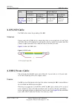
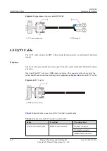


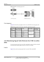


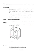


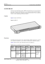

Structure
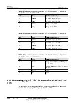
The monitoring signal cable between the APMI and the BBU has an RJ-45 connector at one end
and four bare wires at the other end.
shows the monitoring signal cable between
the APMI and the BBU.
Figure 4-17
Monitoring signal cable between the APMI and the BBU
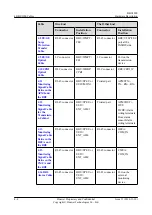
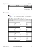
Pin Assignment
describes the pin assignment for the wires of the monitoring signal cable between
the APMI and the BBU.
Table 4-13
Pin assignment for the wires of the monitoring signal cable between the APMI and
the BBU
Pin on the
RJ-45
Connector
Color
X2 to X5 Ends
Description
Terminal on the
APMI
X1.1
White
X2
Twisted pair
TX+
X1.2
Orange
X3
TX-
X1.4
Blue
X4
Twisted pair
RX+
X1.5
White
X5
RX-
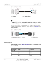
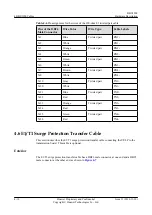
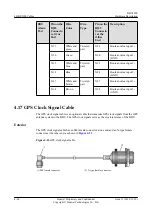
4.12 Monitoring Signal Cable for the Transmission Cabinet
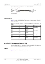
The monitoring signal cable for the transmission cabinet is used to connect the alarm ports of
the APMI, DCDU, and door status sensor to the BBU.
Appearance
One end of the monitoring signal cable is an RJ-45 connector and the other end consists of three
pairs of wires in different colors, as shown in
4 BBU3900 Cables
BBU3900
Hardware Description
4-18
Huawei Proprietary and Confidential
Copyright © Huawei Technologies Co., Ltd.
Issue 11 (2010-11-10)
Содержание BBU3900
Страница 1: ...BBU3900 V200 Hardware Description Issue 11 Date 2010 11 10 HUAWEI TECHNOLOGIES CO LTD ...
Страница 2: ......
Страница 4: ......
Страница 14: ......
Страница 56: ......


