background image

27

4

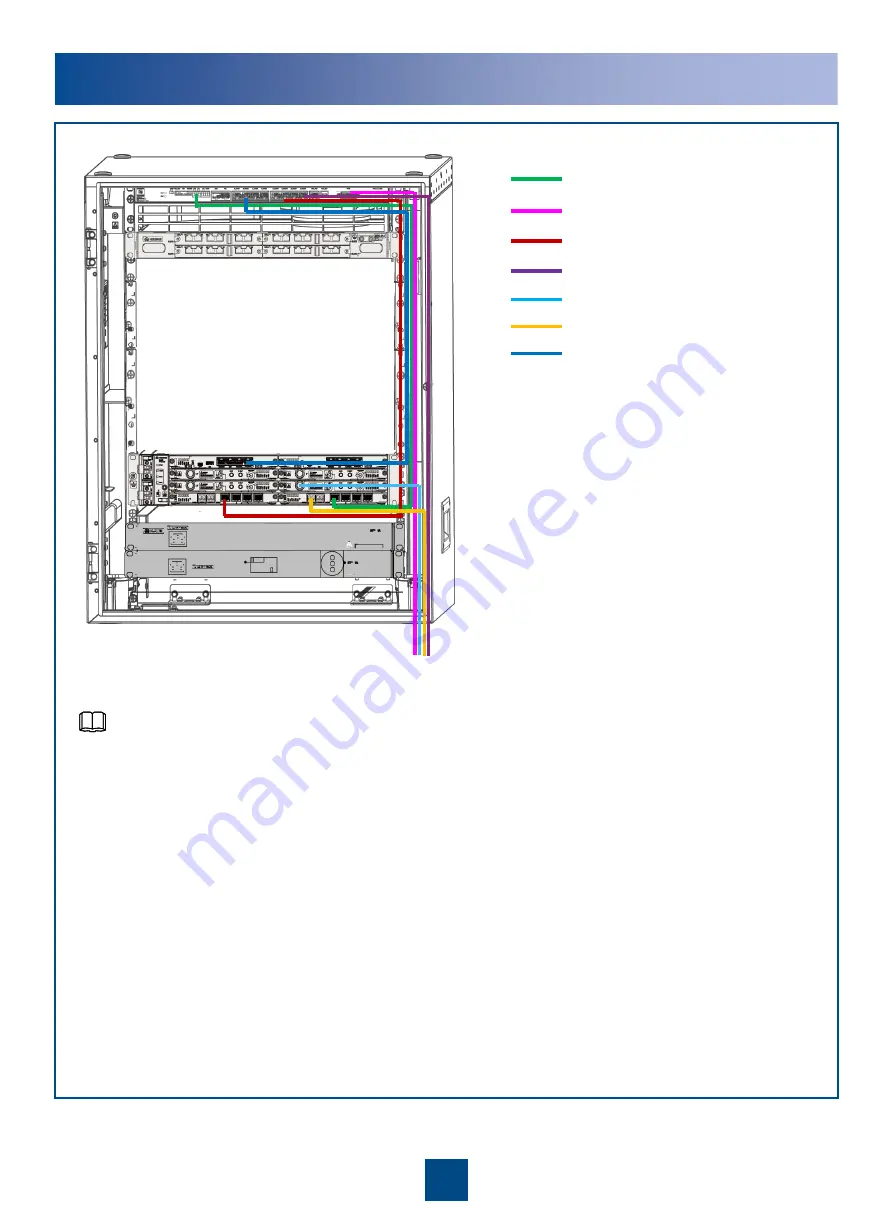
Installing Service Cables of the Devices

E1 cable (adapter cable)

E1 cable (output cable)

Ethernet cable (adapter cable)

Ethernet cable (output cable)

IF cable

Optical fiber

Monitoring cable

The service cables in the AMP30H/TMC11H cabinet are routed in the same way.

When the RTN 900 and the wireless equipment are installed in the same cabinet, 
the E1 and Ethernet cables do not need to be connected to the surge protection 
box and are directly connected to the peer equipment.

NOTE

Содержание APM30H

Страница 1: ...HUAWEI TECHNOLOGIES CO LTD OptiX RTN 900 Radio Transmission System IDU Quick Installation Guide for Outdoor Cabinets APM30H TMC11H Cabinets Ver E Issue 01 Date 2019 03 30 ...

Страница 2: ...ective holders Notice The purchased products services and features are stipulated by the contract made between Huawei and the customer All or part of the products services and features described in this document may not be within the purchase scope or the usage scope Unless otherwise specified in the contract all statements information and recommendations in this document are provided AS IS withou...

Страница 3: ...t perform operations on high voltage and AC power supply facilities or on a tower or mast in the case of thunderstorm Failure to do so causes serious injury or death Ground the device before powering it on Failure to do so causes damage to the device or personal injury Power off the device before performing operations on the power supply facilities High power radio frequency signals are harmful to...

Страница 4: ...rs from getting into the NE which may result in faults on the NE Boards are fragile and valuable When handling or placing a board exercise caution and put it into a dedicated packing box Holding a board without hand protection Wearing ESD gloves Wearing an ESD strip Hold the front panel of a board with hands Instructions and Precautions for Handling Boards CAUTION CAUTION CAUTION ...

Страница 5: ...ons for Handling Power Cable Terminals Do not pick up the tail end of the red latch by using a finger or a screwdriver to avoid damage Press the front of the red latch Properly move the red latch outwards 1 2 1 2 2 2 1 1 CAUTION ...

Страница 6: ...l Socket wrench Torque wrench Hex key Wire clippers Wire stripper RJ45 crimping tool Diagonal pliers Cold press pliers Needle nose pliers Combination pliers Bayonet wrench Utility knife Claw hammer Hammer drill Marker Ladder Electric iron Antistatic gloves Heat gun Multimeter ESD gloves Binding strap Insulation tape ESD wrist strap Impact tool File Vacuum cleaner ...

Страница 7: ...ronous data port Clock port CLK High precision time port TOD Outdoor cabinet monitoring port MON 16 17 16xE1 ports 4 Alarm input output port 13 14 15 COMBO ports Port for the ESD wrist strap MN1 subboard 19 18 18 19 Ground screw DC C power socket Caution See Precautions for Handling Power Cables NE status indicator 1 2 3 Mini USB port 5 IF ports to the ODU ODU switches 6 Radio link status indicato...

Страница 8: ...External clock port External time port Outdoor cabinet monitoring port Front View of the RTN 910A E1 port 11 IF port ODU power switch Input power port Synchronous Asynchronous data port External clock time port Ethernet service port NM COM port Orderwire phone port External alarm port Based on different board configurations the positions of the actual IDU ports may be different from the positions ...

Страница 9: ...11 STM 1 service port ESD port External clock port External time port 1 Bypass E1 port XPIC input output ports 10 12 11 USB port 12 IF port E1 port ODU power switch Based on different board configurations the positions of the actual IDU ports may be different from the positions shown in the figure NOTE Input power port ESD port IF port ODU power switch NM COM port External clock port External time...

Страница 10: ...echnical Specifications Dimensions mm 700 H x 600 W x 480 D Ambient temperature 40 C to 50 C Sunshine radiation 1120 10 W m2 Left View of the APM30H Cabinet b Right View of the APM30H Cabinet c The exterior of the TMC11H cabinet is the same as the exterior of the APM30H cabinet NOTE ...

Страница 11: ...d The monitoring board varies depending on the cabinet version NOTE Fan unit SLPU SOU Internal Structure of the APM30H Cabinet AC Power Supply Cabinet Version Fan Box Monitoring Board APM30H TMC11H Ver E FAN 02E CCUB board APM30H TMC11H Ver D FAN 02D CMUEA board APM30H TMC11H Ver C FAN 02B HPMI and CMUE boards APM30H TMC11H Ver B FAN 02A HPMI and CMUA boards EPU frame Heater Fan unit ...

Страница 12: ...wn in the figure is not for the concrete pad The recommended distance between the cabinets is 40 mm and the maximum distance between the cabinets is 150 mm If the noise reduction module NRM is required the distance between the cabinets is 150 mm Installing the APM30H cabinet on the base APM30H IBBS200D T battery cabinet IBBS200D T Base The installation scenarios of the TMC11H cabinet are the same ...

Страница 13: ...e pad The height of the concrete pad must meet the heat dissipation and waterproofing requirements of the cabinet The concrete pad must be 200 mm higher than the ground and the horizontal error must be less than 5 mm when the pad is cast Do not use the base as a positioning tool when drilling Otherwise the paint on the base may be scratched Concrete pad Unit mm CAUTION ...

Страница 14: ...asher flat washer and bolt Flat washer 12 Remove the front cover of the base Adjust the base level Tighten the bolts by using a torque wrench Position the base and then screw the bolt with the spring washer and flat washer Adjust the base level by adding certain pads to the bolts between the base and the concrete pad ...

Страница 15: ...nts 10 Moving the Cabinet onto the Base b Install the lifting lugs Tie the ropes Store the plastic screws properly Maximum 90 Plastic screw Lifting lug Move the cabinet onto the base Remove the ropes and install the plastic screws Before installing the plastic screws clean the installation holes to ensure that they are free of metal shavings Select a proper method to move the cabinet as required T...

Страница 16: ...ets Optional d Remove the four plastic screws from the top of the lower cabinet M12x30 bolt x4 Remove the two cover plates from the top of the lower cabinet Remove the four rubber caps from the bottom of the upper cabinet Stack the cabinets and then secure the cabinets with the four bolts Rubber cap x4 To ensure the waterproof performance of the cabinet retain the cover plates properly for the rou...

Страница 17: ...nance socket and other devices The RTN 980 cannot be installed in this installation scenario When two or more RTN 900 devices are installed in a cabinet install from top to bottom Reserve 1 U space between the RTN 900 and the heater If no maintenance socket is installed install the heater optional at the bottom of the cabinet by default In this installation scenario a maximum of 8 U space is avail...

Страница 18: ...RTN 900 devices are installed in a cabinet install from top to bottom Due to space constraints select either the maintenance socket or the AC heater when the RTN 980 is installed Reserve 1 U space between the RTN 900 and the heater If no maintenance socket is installed install the heater optional at the bottom of the cabinet by default In this installation scenario a maximum of 10 U space is avail...

Страница 19: ... 900 in the APM30H Cabinet Fixing the Floating Nuts a Installing the RTN 900 b Floating nut Installation hole When installing the RTN 900 in the TMC11H cabinet use the same method NOTE Remove the guide rail if any from the installation position NOTE ...

Страница 20: ...a general purpose surge protection unit for E1 or T1 services A UELP is used for surge protection of four E1 or T1 signals The UFLP is a general purpose surge protection unit for FE or GE services A UFLP can be used for surge protection of two FE or GE signals NOTE The SLPU is generally equipped with two UELP boards and one UFLP board If more than eight E1 signals are transmitted one or two extra ...

Страница 21: ...pose UK standard The SOU which is an optional component provides the transit function for the AC powered equipment of a customer Configured with the four outlet types the cabinets support different SOU types of different countries The SOU is preferably installed in the bottom 1U space of the cabinet NOTE Install the SOU Install the SOU Install the power cable for the SOU ...

Страница 22: ...alled above the SOU When the temperature inside the cabinet is lower than 0 C the heater starts working When the temperature inside the cabinet is higher than 15 C the heater stops working The maximum power of the heater during the heating process is 300 W NOTE Install the power cable for the heater APM30H Cabinet TMC11H Cabinet power cable for the heater power cable for the heater AC input power ...

Страница 23: ...b Installing and Routing the Cables WARNING When installing the PGND cables in the TMC11H cabinet use the same method The ground cables and signal cables must be bound separately or must be separated from each other to minimize mutual interference NOTE Ground bar PGND cable of the SLPU PGND cable of the RTN 900 Ground bar ...

Страница 24: ...ctive cap and open the protective cap Tighten the AC input protective cap Route the power cables into the cabinet along the inner left side of the cabinet connect each wire to the corresponding terminal and use a torque screwdriver to tighten the screws The short circuiting bar does not need to be removed when single phase 220 V power is input The short circuiting bar must be removed when three ph...

Страница 25: ...pply to the RTN 900 The port type can be EPC4 connector NOTE A B C The power terminal of the RTN 905 980 differs from that of the RTN 910A 950 950A NOTE RTN 910A 950 950A RTN 905 RTN 980 Before installing power cables ensure that the circuit breaker of the power output terminal is set to the OFF state Binding strap Cable bridge ...

Страница 26: ...y Cabinet c Either IBBS200D or BBS200T is used Installing the Power Cables for the Fan Assembly in the IBBS200D Battery Cabinet d APM30H For details on how to make EPC4 connectors see Appendixes NOTE NOTE INPUT Base IBBS200D T battery cabinet Base IBBS200D battery cabinet ...

Страница 27: ...Battery Cabinet f L1 N1 Power box of the heating film The power cables for the heating films in the IBBS200D battery cabinet must be routed downward into the power box of the heating film Do not expose the core wires of the power cable outside the power box of the heating film Power box of the heating film CAUTION CAUTION From L1 N1 Load 8 1 1 ...

Страница 28: ...he Power Cables for the RTN 900 in the TMC11H Cabinet b 1 26 3 Installing and Routing the Power Cables DC Power Supply NOTE DC power box cover Remove the cover of the DC power box NEG RTN Install the input power cable Put back the cover of the DC power box 1 2 3 You can select from DC power output terminals LOAD6 LOAD7 and LOAD8 For information about assembling the easy power receptacle pressfit t...

Страница 29: ...put cable IF cable Optical fiber Monitoring cable The service cables in the AMP30H TMC11H cabinet are routed in the same way When the RTN 900 and the wireless equipment are installed in the same cabinet the E1 and Ethernet cables do not need to be connected to the surge protection box and are directly connected to the peer equipment NOTE ...

Страница 30: ...and APM30H TMC11H Ver D and later versions use cable bags to lead out cables NOTE E1 cables for 1xAnea 96 4xDB25 conversion are used For cabinet sharing the Ethernet cables are not connected to the SLPU Instead they are directly connected to the equipment at the opposite end APM30H TMC11H Ver C and earlier versions use rubber blocks to lead out cables and APM30H TMC11H Ver D and later versions use...

Страница 31: ... APM30H TMC11H Ver D and later versions use cable bags to lead out cables If the IF board is IF1 IFU2 IFX2 ISV3 ISU2 ISX2 turn off the ODU PWR switch on the IF board If the IF board is ISM6 skip this operation Off On I O Turning off the ODU PWR switch on the IF board APM30H TMC11H Ver C and earlier versions use rubber blocks to lead out cables and APM30H TMC11H Ver D and later versions use cable b...

Страница 32: ...in 2 TX Orange Pin 3 RX Orange Pin 4 RX Blue Pin 8 TX Blue Pin 5 RX White Blue Pin 7 TX White Blue Pin 8 GND Brown Pin 5 GND Brown Pin 3 6 7 No connected Pin 1 2 4 No connected NOTE When using the CSHU or CSHUA board connect the signal monitoring cable to the MON TOD2 port The pin assignment is the same as that of the CSH or CST board Before installing a signal monitoring cable remove the cable al...

Страница 33: ... Installing Service Cascading Cables f If two or more RTN 905 devices are installed in a single cabinet cascading cables need to be installed if the devices need to be cascaded COMBO port COMBO port NOTE ...

Страница 34: ...ing the Cable Outlet Module Cable Outlet Module a 1 Left cable outlet 2 Right cable outlet The cable outlet module of TMC11H is the same as that of APM30H Sealing Method b NOTE 1 2 Tighten the cable outlet bags ...

Страница 35: ...may be exposed to damages they must be routed through a pipe such as a corrugated PVC pipe to protect them from being damaged A non outdoor cable to be routed out a cabinet must be protected by a pipe The pipe must be led into the cabinet base for about 30 mm to 50 mm but not into the cabinet The pipe end must be sealed with waterproof tapes or silicon gel The pipe must be secured to the cable hol...

Страница 36: ...and do not short circuit the positive and negative poles of the batteries Otherwise the batteries may be burnt and the installation personnel may be injured Move the baffle plate upward and then secure it Battery circuit breaker labeled BAT Install the power cables for the batteries Remove the protecting hood Install the copper bar for serial connections Install the positive and negative cables a ...

Страница 37: ...act No What to Check For 1 The layout of the cabinet complies with the engineering designs 2 The base is installed securely 3 The deviation of the cabinet is less than 3 mm horizontally and not more than 3 mm vertically 4 All the bolts are tightened especially those for electrical connections The flat washers and spring washers are installed completely and properly 5 The cabinet is neat and clean ...

Страница 38: ...The lugs at both ends of the power cable or PGND cable are soldered or crimped securely 5 Bare wires and lug handles at the wiring terminals are wrapped tightly by using insulation tapes or heat shrink tubes 6 The flat washers and spring washers are mounted securely to all the wiring terminals 7 The connectors of all cables are securely linked especially those at the bottom of the cabinet 8 The ca...

Страница 39: ... voltage range of the DC output power to the EPU 43 2 V DC to 57 V DC Normal statuses of the indicators on the CCUB RUN indicator Blinking ALM indicator OFF In the case of AC power supply This part describes only the process for checking the power on status of the AC power equipment When checking the power on status of the DC power equipment refer to the process for checking the power on status of...

Страница 40: ...ntact between the contact terminal and the end of the jacket of the cable is required When placing the contact terminal on the conductor securely to the end of the jacket ensure that the L2 part of the conductor that sticks out of the contact terminal cannot exceed 2 mm Press the end of the contact terminal on the conductor by using the crimping tool Connect the contact terminal to the power serie...

Страница 41: ... conductor into the hole cannot be less than 11 mm Push back the sliding blocks until they are in position Then check whether the conductors are secure by gently pulling the cables If the conductor slides outward or the core wire of the conductor is exposed outside the hole for the conductor remove the conductor cut the split wires and then strip the jacket and install the conductor again Push the...

Страница 42: ... the extraction tool Remove the fuse from the case Replace the fuse by using the extraction tool a b c Fuse Fuse Align the bulge on the extraction tool with the hole on the fuse EPU EPU Remove the fuse by using the extraction tool ...

Страница 43: ...shing paint in an appropriate color based on the original coating Before the repair shake the paint properly Then use the small brush inside the bottle to absorb paint and evenly spread the paint on the damaged area till the scratch damage is covered Note that the paint coating applied needs to be thin and even Ensure that drops do not appear on the paint coating and the surface is smooth Drying P...

Страница 44: ...HUAWEI TECHNOLOGIES CO LTD Huawei Industrial Base Bantian Longgang Shenzhen 518129 People s Republic of China www huawei com ...

Отзывы: