background image

NOTICE

l

When you remove a section of the jacket, do not damage the shield layer of the twisted-
pair cable.

l

When you remove the shield layer, do not damage the insulation of the twisted-pair cable.

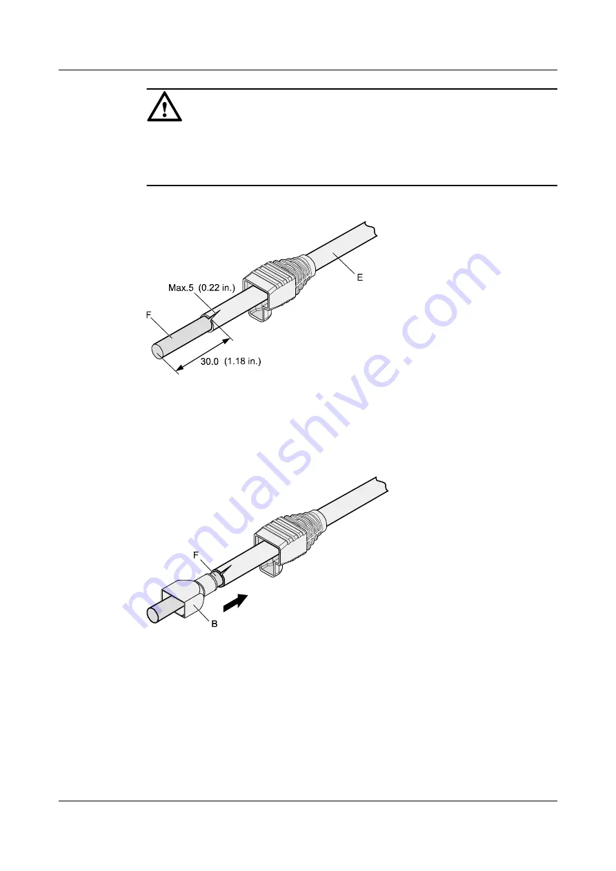
Figure 5-17

 Removing the jacket of a twisted-pair cable (unit: mm (in.))


Step 3

Fit the metal shell onto the twisted-pair cable. The shield layer is covered by the metal shell,
as shown in 

Figure 5-18

.

Figure 5-18

 Fitting the metal shell onto the twisted-pair cable


Step 4

Fit the metal shell onto the twisted-pair cable until the shield layer is covered completely.
Along the edge of the metal shell, cut off the aluminum foil shield layer and ensure that there
is no surplus copper wire. The exposed twisted-pair cable is about 20 mm (0.79 in.) long, as
shown in 

Figure 5-19

.

AP2030DN
Hardware Installation and Maintenance Guide

5 Appendix

Issue 05 (2016-07-22)

Huawei Proprietary and Confidential

Copyright © Huawei Technologies Co., Ltd.

37

Содержание AP2030DN

Страница 1: ...AP2030DN Hardware Installation and Maintenance Guide Issue 05 Date 2016 07 22 HUAWEI TECHNOLOGIES CO LTD ...

Страница 2: ... be within the purchase scope or the usage scope Unless otherwise specified in the contract all statements information and recommendations in this document are provided AS IS without warranties guarantees or representations of any kind either express or implied The information in this document is subject to change without notice Every effort has been made in the preparation of this document to ens...

Страница 3: ...ion which if not avoided will result in death or serious injury Indicates a potentially hazardous situation which if not avoided could result in death or serious injury Indicates a potentially hazardous situation which if not avoided may result in minor or moderate injury Indicates a potentially hazardous situation which if not avoided could result in equipment damage data loss performance deterio...

Страница 4: ...n is added l Installing the Device into Other Junction Boxes l Installing the Device on a Wall or Ceiling Issue 04 2015 12 12 This version has the following updates Optimized the section Logging In to the AP Issue 03 2015 08 05 This version has the following updates Updated the packing list Issue 02 2015 05 18 This version has the following updates Modified descriptions about PoE fault troubleshoo...

Страница 5: ...hecking the Device After Installation 19 2 8 Powering on the Device 19 3 Logging In to the AP 20 3 1 Logging In to the Device Using STelnet Telnet 21 4 Hardware Failures 22 4 1 A Device Fails to Be Powered On 23 5 Appendix 25 5 1 On site Cable Assembly and Installation 26 5 1 1 Cable Assembly Precautions 26 5 1 2 Assembling Power Cables 27 5 1 3 Assembling Ethernet Cables 35 5 1 4 Installing Cable...

Страница 6: ... 6 Specifications for Laying Out Grounding Cables 81 5 4 Engineering Labels for Cables 82 5 4 1 Introduction to Labels 82 5 4 2 Engineering Labels for Optical Fibers 90 5 4 3 Engineering Labels for Network Cables 93 5 4 4 Engineering Labels for User Cables 94 5 4 5 Engineering Labels for Power Cables 95 5 5 Guide to Using Optical Modules 98 5 6 Fault Tag 101 5 7 Installation Checklist 102 AP2030DN...

Страница 7: ... a hidden indicator and a sliding panel The AP2030DN can connect to wireless terminals through wireless connections or to wired terminals using wired cables 1 1 Device Structure 1 2 Indicator Description 1 3 Basic Specifications 1 4 Ordering Information AP2030DN Hardware Installation and Maintenance Guide 1 AP2030DN Overview Issue 05 2016 07 22 Huawei Proprietary and Confidential Copyright Huawei ...

Страница 8: ...AP2030DN No Name Description 1 Phone Phone interface connects to a traditional PSTN 2 GE PoE 10 100 1000 Mbit s interface connects to the wired Ethernet and supports PoE power input 3 ETH0 ETH3 10 100 Mbit s interface connects to the wired Ethernet AP2030DN Hardware Installation and Maintenance Guide 1 AP2030DN Overview Issue 05 2016 07 22 Huawei Proprietary and Confidential Copyright Huawei Techn...

Страница 9: ... delivered with the device otherwise the device maybe damaged 1 2 Indicator Description AP2030DN provides only one indicator as shown in Figure 1 2 Figure 1 2 Indicator on the AP2030DN Indicator ETH0 ETH1 ETH2 Phone ETH3 NOTE l The indicator is located inside the panel which turns on after the AP is powered on l Indicator colors may vary slightly at different temperature AP2030DN Hardware Installa...

Страница 10: ...ware is uploaded and started the indicator remains steady green Running status Green Blinking once every 2s 0 5 Hz The system is running properly the Ethernet connection is normal and STAs are associated with the AP Blinking once every 5s 0 2 Hz The system is running properly the Ethernet connection is normal and no STA is associated with the AP The system is in low power consumption state AP2030D...

Страница 11: ...Steady on A fault that affects services has occurred such as a DRAM detection failure or system software loading failure The fault cannot be automatically rectified and must be rectified manually 1 3 Basic Specifications Table 1 3 Basic specifications of the AP2030DN Item Description Technical specifications Dimensions outside the wall H x W x D 25 mm x 140 mm x 86 mm Dimensions inside the wall H ...

Страница 12: ... m to 5000 m Temperature decreases by 1 C every time the altitude increases 300 m Storage temperature 40 C to 70 C Operating humidity 5 to 95 non condensing IP rating IP20 Atmospheric pressure 70 kPa to 106 kPa 1 4 Ordering Information To place an order contact technical support personnel Part Number Description 50082640 Broadband Network Terminal AP2030DN 5 RJ45 2 RJ11 11ac 2 2 Double Frequency A...

Страница 13: ...2 4 Determining the Installation Position 2 5 Installing the Device 2 6 Cable Connection 2 7 Checking the Device After Installation 2 8 Powering on the Device AP2030DN Hardware Installation and Maintenance Guide 2 AP Installation Issue 05 2016 07 22 Huawei Proprietary and Confidential Copyright Huawei Technologies Co Ltd 7 ...

Страница 14: ...UTION Only the qualified personnel are permitted to install and remove the device and its accessories Before installation and operation read the safety precautions carefully Tool Preparation To install APs prepare tools listed in Table 2 1 Table 2 1 Tools Phillips screwdriver ESD gloves Diagonal pliers RJ45 crimping tool Cable cutter Wire stripper Network cable tester Multimeter 2 2 Installation F...

Страница 15: ...tact the supplier Usually the packing list contains the following items l AP device l Screws l Quick Start Guide l Warranty card l MAC address label l SN label NOTE If a PoE adapter is required you need to purchase it separately 2 4 Determining the Installation Position Figure 2 2 shows dimensions of the AP2030DN AP2030DN Hardware Installation and Maintenance Guide 2 AP Installation Issue 05 2016 ...

Страница 16: ...residents l Make the engineering design by fully considering such factors as hydrology geology earthquake electric power and traffic The selected site should comply with the environment design specifications of communications equipment l Indoor devices are usually mounted on a wall or ceiling using sheet metal mounting brackets The installation position is determined by the site survey Leave at le...

Страница 17: ...se mounting brackets 2 5 1 Installing the Device into an 86 Type Box 1 Use a screwdriver to remove the 86 type panel from the wall skip this step if no 86 type panel is installed on the wall 2 Connect the network cable to the GE PoE interface and the phone cable to the phone interface 3 Install the device that has cables properly connected to the 86 type box as shown in the following figure AP2030...

Страница 18: ... at the right and left of the device with the screw holes on the box and secure the device on the box with a screwdriver 5 Close the panel to complete installation 2 5 2 Installing the Device into Other Junction Boxes AP2030DN Hardware Installation and Maintenance Guide 2 AP Installation Issue 05 2016 07 22 Huawei Proprietary and Confidential Copyright Huawei Technologies Co Ltd 12 ...

Страница 19: ... on the junction box are 83 5 mm distant from each other 60mm 83 5mm 2 Use screws to fix the mounting bracket to the junction box Ensure that the UP arrowhead points upwards If the screw holes on the junction box do not match the M4 screws customers need to prepare the fastening screws by themselves 1 N m M4 3 Connect the network cable to the GE PoE interface and the telephone line to the phone in...

Страница 20: ...e mounting bracket and secure theAP on the mounting bracket with machine screws 1 N m M4 5 Close the panel 2 5 3 Installing the Device on a Wall or Ceiling AP2030DN Hardware Installation and Maintenance Guide 2 AP Installation Issue 05 2016 07 22 Huawei Proprietary and Confidential Copyright Huawei Technologies Co Ltd 14 ...

Страница 21: ...les at the marked positions and install the plastic expansion tubes a b Ø6 35mm a Use a 6 mm drill bit to drill holes at the marked positions b Hammer the plastic expansion tubes into the holes 3 Use the flat washer and self tapping screws to fasten the mounting bracket to the wall or ceiling If the device is installed against the wall ensure that UP arrowhead faces upwards AP2030DN Hardware Insta...

Страница 22: ...he device align the the screw holes at the right and left of the AP with the screw holes on the mounting bracket and secure theAP on the mounting bracket with machine screws AP2030DN Hardware Installation and Maintenance Guide 2 AP Installation Issue 05 2016 07 22 Huawei Proprietary and Confidential Copyright Huawei Technologies Co Ltd 16 ...

Страница 23: ... 6 Cable Connection Figure 2 3 shows interfaces of the AP2030DN AP2030DN Hardware Installation and Maintenance Guide 2 AP Installation Issue 05 2016 07 22 Huawei Proprietary and Confidential Copyright Huawei Technologies Co Ltd 17 ...

Страница 24: ... Ethernet interface to the upstream PSE Ethernet interface CAT5e cables or higher must be used 3 Ethernet cable Connects the Ethernet interface to the terminal CAT5 cables or higher must be used 4 Phone cable Connects the downstream phone interface to the traditional phone POTS phone or modem equipment AP2030DN Hardware Installation and Maintenance Guide 2 AP Installation Issue 05 2016 07 22 Huawe...

Страница 25: ...rements with maintenance space reserved 2 The device is securely installed 3 The power cables are intact and not spliced 4 Terminals of the power cables are welded or cramped firmly 5 All power cables are not short circuited or reversely connected and must be intact with no damage 6 The power cables and ground cables are separated from other cables and bundled separately 7 Connectors of signal cab...

Страница 26: ...is Chapter 3 1 Logging In to the Device Using STelnet Telnet AP2030DN Hardware Installation and Maintenance Guide 3 Logging In to the AP Issue 05 2016 07 22 Huawei Proprietary and Confidential Copyright Huawei Technologies Co Ltd 20 ...

Страница 27: ... in to the AC through a remote terminal and run the following command to check the IP address of the device l V200R005C30 and earlier versions display ap run info id ap id l V200R006 and later versions display ap all Step 1 Use network cables and a LAN switch to connect the PC to the network interface of the device Step 2 Assign the PC with an IP address on the same network segment as the default ...

Страница 28: ...common methods for troubleshooting typical hardware faults 4 1 A Device Fails to Be Powered On AP2030DN Hardware Installation and Maintenance Guide 4 Hardware Failures Issue 05 2016 07 22 Huawei Proprietary and Confidential Copyright Huawei Technologies Co Ltd 22 ...

Страница 29: ...fail If the device has a built in power supply the device itself may be faulty PoE power supply l The power sourcing equipment does not support the PoE function or is faulty l The power sourcing equipment is incorrectly configured the PoE function is disabled or the power off time range is improperly set l The line is faulty the network cable or distribution frame is damaged l The device is faulty...

Страница 30: ...echnical support personnel or Huawei agent and ask them to replace the device PoE power supply 1 Check whether the power sourcing equipment supports PoE or is faulty 2 Check whether the configuration on the power sourcing equipment causes PoE power supply errors such as the PoE function is disabled or the power off time range is incorrectly set 3 Check whether the network cable or distribution fra...

Страница 31: ...peration 5 3 Equipment Grounding Specifications 5 4 Engineering Labels for Cables 5 5 Guide to Using Optical Modules 5 6 Fault Tag 5 7 Installation Checklist AP2030DN Hardware Installation and Maintenance Guide 5 Appendix Issue 05 2016 07 22 Huawei Proprietary and Confidential Copyright Huawei Technologies Co Ltd 25 ...

Страница 32: ...assembly l Hold terminals of cables instead of pulling the cables themselves when installing or removing cable components l Take the following precautions when cutting or stripping cables Make cables slightly longer than necessary Coil cables longer than 2 m 6 56 ft after cutting Bind and fasten the coils using bundling ropes The inner diameters of the coils should be larger than 20 times the oute...

Страница 33: ...mponents of an OT terminal and a power cable Figure 5 1 Components of an OT terminal and a power cable A Heat shrinkable tubing B Bare crimping terminal C Insulation D Conductor Procedure Step 1 Based on the cross sectional area of the cable conductor strip a length of insulation coating C to expose the conductor D of length L1 as shown in Figure 5 2 The recommended values of L1 are listed in Tabl...

Страница 34: ...l Area of Conductor mm2 in 2 Value of L1 mm in 1 0 002 7 0 28 10 0 015 11 0 43 1 5 0 002 7 0 28 16 0 025 13 0 51 2 5 0 004 7 0 28 25 0 039 14 0 55 4 0 006 8 0 31 35 0 054 16 0 63 6 0 009 9 0 35 50 0 077 16 0 63 NOTE If you are proficient in assembling OT terminals and power cables you can obtain the value of L1 by comparing the part to be crimped with the power cable Step 2 Put the heat shrinkable...

Страница 35: ...n Step 4 Crimp the joint parts of the bare crimping terminal and the conductor as shown in Figure 5 4 NOTE The shapes of crimped parts may vary with the crimping dies Figure 5 4 Crimping the joint parts of the bare crimping terminal and the conductor OT terminal Step 5 Push the heat shrink tubing A toward the connector until the tube covers the crimped part and then use a heat gun to heat the tube...

Страница 36: ...Assembling the JG Terminal and Power Cable Context Figure 5 6 shows the components of a JG terminal and a power cable Figure 5 6 Components of a JG terminal and a power cable A JG terminal B Heat shrinkable tubing C Insulation layer of a power cable D Conductor of a power cable AP2030DN Hardware Installation and Maintenance Guide 5 Appendix Issue 05 2016 07 22 Huawei Proprietary and Confidential C...

Страница 37: ...lue of L as required Figure 5 7 Stripping a power cable JG terminal Table 5 2 Mapping between the cross sectional area of the conductor and the value of L Cross Sectional Area of Conductor mm2 in 2 Value of L mm in 16 0 025 13 0 51 25 0 039 14 0 55 35 0 054 16 0 63 50 0 077 16 0 63 Step 2 Put the heat shrink tubing onto the bare crimping terminal as shown in Figure 5 8 AP2030DN Hardware Installati...

Страница 38: ...minal and the conductor as shown in Figure 5 9 Figure 5 9 Crimping the joint parts of the bare crimping terminal and the conductor JG terminal Step 5 Push the heat shrink tubing toward the connector until the tube covers the crimped part and then use a heat gun to heat the tube as shown in Figure 5 10 Figure 5 10 Heating the heat shrink tubing JG terminal AP2030DN Hardware Installation and Mainten...

Страница 39: ... power cable Procedure Step 1 Strip a part of the insulation to expose the cable conductor with a length of L1 as shown in Figure 5 12 The recommended values of L1 are listed in Table 5 3 NOTICE When you strip a power cable do not damage the conductor of the cable Figure 5 12 Stripping a power cable cord end terminal AP2030DN Hardware Installation and Maintenance Guide 5 Appendix Issue 05 2016 07 ...

Страница 40: ... cord end terminal onto the conductor and ensure that the conductor is aligned with the edge of the cord end terminal as shown in Figure 5 13 NOTICE After the conductor is fed into the cord end terminal the protruding part of the conductor must not be longer than 1 mm 0 04 in Figure 5 13 Putting the cord end terminal onto the conductor Step 3 Crimp the joint parts of the cord end terminal and the ...

Страница 41: ... 2 Maximum Width of Crimped Terminal W1 mm in 0 25 0 0004 1 0 04 0 5 0 0008 1 0 04 1 0 0 0015 1 5 0 06 1 5 0 0023 1 5 0 06 2 5 0 0039 2 4 0 09 4 0 006 3 1 0 12 6 0 009 4 0 16 10 0 015 5 3 0 21 16 0 025 6 0 24 25 0 039 8 7 0 34 35 0 054 10 0 39 End 5 1 3 Assembling Ethernet Cables Assembling the Shielded RJ45 Connector and Ethernet Cable AP2030DN Hardware Installation and Maintenance Guide 5 Append...

Страница 42: ...ires Procedure Step 1 Fit the jacket of the connector onto the Ethernet cable as shown in Figure 5 16 Figure 5 16 Fitting the jacket of the connector onto the Ethernet cable Step 2 Remove a 30 mm 1 18 in long section of the jacket cut off the nylon twine inside the jacket and cut a no more than 5 mm 0 20 in cleft in the jacket as shown in Figure 5 17 AP2030DN Hardware Installation and Maintenance ...

Страница 43: ...l shell as shown in Figure 5 18 Figure 5 18 Fitting the metal shell onto the twisted pair cable Step 4 Fit the metal shell onto the twisted pair cable until the shield layer is covered completely Along the edge of the metal shell cut off the aluminum foil shield layer and ensure that there is no surplus copper wire The exposed twisted pair cable is about 20 mm 0 79 in long as shown in Figure 5 19 ...

Страница 44: ...res through the wire holder C G Figure 5 21 Cable locations in a wire holder White Green Green White Orange Orange Blue White Blue White Brown Brown Step 6 Align the four pairs of cables in the holder as shown in Figure 5 22 The connections between the wires and the pins are shown in Figure 5 23 and listed in Table 5 5 AP2030DN Hardware Installation and Maintenance Guide 5 Appendix Issue 05 2016 0...

Страница 45: ...n 8 Pin 1 Table 5 5 Connections between wires and pins using a straight through cable as an example Matching Pins of Wires Wire Color 1 White Orange 2 Orange 3 White Green 4 Blue 5 White Blue 6 Green 7 White Brown AP2030DN Hardware Installation and Maintenance Guide 5 Appendix Issue 05 2016 07 22 Huawei Proprietary and Confidential Copyright Huawei Technologies Co Ltd 39 ...

Страница 46: ... Figure 5 25 NOTE Ensure that the wire holder is in good contact with the connector body Figure 5 25 Putting the connector body onto the wire holder Step 9 Push the metal shell toward the connector body until the wire holder and the connector body are engaged completely Crimp the connector as shown in Figure 5 26 AP2030DN Hardware Installation and Maintenance Guide 5 Appendix Issue 05 2016 07 22 H...

Страница 47: ...shing the metal shell Step 11 To complete the assembly of the other end repeat Step 1 through Step 10 End Assembling an Unshielded RJ45 Connector and Ethernet Cable Context Figure 5 28 shows the components of an unshielded RJ45 connector and cable AP2030DN Hardware Installation and Maintenance Guide 5 Appendix Issue 05 2016 07 22 Huawei Proprietary and Confidential Copyright Huawei Technologies Co...

Страница 48: ...9 Removing the jacket of a twisted pair cable unit mm in Step 2 Align the four pairs of wires and cut the ends neatly as shown in Figure 5 30 The connections between the wires and the pins are listed in Table 5 6 Figure 5 30 Connections between wires and pins unit mm in C 16 White Orange White Green Orange Blue White Blue Green White Brown Brown Pin 8 Pin 1 AP2030DN Hardware Installation and Maint...

Страница 49: ...ng the connector Step 4 To complete the assembly of the other end repeat Step 1 through Step 3 End Checking the Appearance of Contact Strips Context l To ensure proper contact between the crimped wires and the wire conductors the heights and sizes of the contact strips must be standard and the same l The contact strips must be parallel to each other with an offset of less than 5 The top margin of ...

Страница 50: ...tact strips are of the same height The height should be 6 02 0 13 mm 0 237 0 005 If a measuring tool is not available you can compare the connector with a standard connector Figure 5 32 shows an unqualified piece and Figure 5 33 shows a qualified piece NOTE All unqualified pieces must be crimped again Figure 5 32 Contact strips of different heights Figure 5 33 Contact strips of the same height Ste...

Страница 51: ...ors are well aligned and intact If a separator is skewed and cannot be fixed replace it with a new RJ45 connector Figure 5 36 shows an unqualified piece Figure 5 36 Skewed plastic separators Step 5 Hold the connector with the side facing towards you and check whether you can see the cross sections of the wires Ensure that the ends of the wires are in good contact with the edge AP2030DN Hardware In...

Страница 52: ...itch to network devices Table 5 7 lists the connections of core wires in a straight through cable Table 5 7 Connections of core wires in a straight through cable RJ45 Connector 1 RJ45 Connector 2 Core Wire Color Twisted or Not 2 2 Orange Twisted 1 1 Orange White 6 6 Green Twisted 3 3 Green White 4 4 Blue Twisted 5 5 Blue White 8 8 Brown Twisted 7 7 Brown White l Crossover cables are connected in a...

Страница 53: ...Feed both connectors of the cable into the ports of the cable tester Step 2 After the connectors are properly inserted turn on the tester If the indicators from 1 to G turn on simultaneously you can infer that the pins work normally and the wires are correctly connected NOTE Turn the switch to the S position to slow down lighting of the indicators so that you can see the indicators more clearly as...

Страница 54: ...hich the indicators turn on which depends on the wire connections of a crossover cable The Ethernet cable is qualified if the indicators turn on in the following sequence At the master left section of the tester the indicators turn on in the sequence of 1 8 G At the slave right section of the tester the indicators turn on in the sequence of 3 6 1 4 5 2 7 8 G If the indicators do not come on in thi...

Страница 55: ...the same For example in this document the adapters of cable connectors have separate interfaces In the actual situation the adapters may have interfaces fixed on equipment Use dedicated tools provided or specified by Huawei and follow the installation procedure described here Bending Radius Unless otherwise specified bending radius R of cables or fibers must meet the requirements listed in Table 5...

Страница 56: ...r adapter may be damaged l When removing densely aligned cables or fiber connectors use dedicated pliers such as cable pulling pliers and fiber pulling pliers l Do not twist bend stretch or extrude fibers during installation l Cover the idle fiber connectors with dust caps Remove the dust caps before using the fiber connectors Requirements for Cable Routing l To protect cables remove the burrs in ...

Страница 57: ...g sleeve is installed as shown in Figure 5 43 where A is correct and B is incorrect Figure 5 43 Installing an OT terminal showing the orientation of crimping sleeve b Place the spring washer and flat washer in turn mount a matching screw and fasten it clockwise as shown in Figure 5 44 AP2030DN Hardware Installation and Maintenance Guide 5 Appendix Issue 05 2016 07 22 Huawei Proprietary and Confide...

Страница 58: ... you install two OT terminals on a post ensure that the two terminals can be installed on the post and that the electrical connecting pieces have a large contact area Two OT terminals can be installed using any of these methods Bend the upper OT terminal at a 45 or 90 degree angle as shown in Figure 5 46 Cross the two terminals as shown in Figure 5 47 AP2030DN Hardware Installation and Maintenance...

Страница 59: ... To remove an OT terminal loosen the screw counterclockwise End Installing the Cord End Terminal Procedure Step 1 Hold a cord end terminal upright and place it on a terminal jack as shown in Figure 5 48 To ensure bump contact and dense connection place the plain side of the terminal outwards AP2030DN Hardware Installation and Maintenance Guide 5 Appendix Issue 05 2016 07 22 Huawei Proprietary and ...

Страница 60: ... the terminal is less than 2 mm 0 079 in in length l Do not press the insulation of the terminal l Insert only one terminal into one jack Step 3 Move the cable slightly and ensure that it is securely connected Step 4 Before you remove a cord end terminal loosen the screw counterclockwise End Installing Ethernet Adapters AP2030DN Hardware Installation and Maintenance Guide 5 Appendix Issue 05 2016 ...

Страница 61: ...igure 5 51 Figure 5 51 Feeding the male shielded connector into the female shielded connector Step 3 When you hear a click the cable connector is completely inserted in the port The clip on the cable connector pops up to fix the connector in the port Pull the connector slightly and ensure that it is securely connected as shown in Figure 5 52 AP2030DN Hardware Installation and Maintenance Guide 5 A...

Страница 62: ...Removing a shielded Ethernet connector End Installing an Unshielded Ethernet Connector Procedure Step 1 Hold the male and female connectors with the male connector facing the female connector as shown in Figure 5 54 AP2030DN Hardware Installation and Maintenance Guide 5 Appendix Issue 05 2016 07 22 Huawei Proprietary and Confidential Copyright Huawei Technologies Co Ltd 56 ...

Страница 63: ...ector Step 3 A crisp click indicates that the connector is locked by the locking key Pull the connector slightly and ensure that it is securely connected Figure 5 56 shows an installed Ethernet connector Figure 5 56 Installed unshielded Ethernet connector AP2030DN Hardware Installation and Maintenance Guide 5 Appendix Issue 05 2016 07 22 Huawei Proprietary and Confidential Copyright Huawei Technol...

Страница 64: ...r connectors you must use a dedicated tool if the connectors are densely installed Cleaning Fiber Connectors Procedure Step 1 Clean the pins of a fiber connector by using lint free cotton and alcohol Step 2 Clean the pins again by using dust free cotton If necessary clean the pins by using an air gun Ensure that the pins are free from any fiber or debris End Installing an FC Fiber Connector AP2030...

Страница 65: ...nnector with the female connector and gently push the male connector until it is completely seated in the female connector as shown in Figure 5 59 Figure 5 59 Feeding the male connector into the female connector Step 4 Fasten the locking nut clockwise and ensure that the connector is securely installed as shown in Figure 5 60 AP2030DN Hardware Installation and Maintenance Guide 5 Appendix Issue 05...

Страница 66: ...fiber connector End Installing an LC Fiber Connector Procedure Step 1 Remove the dustproof cap of the LC fiber connector and store it for future use Step 2 Align the core pin of the male connector with that of the female connector as shown in Figure 5 62 AP2030DN Hardware Installation and Maintenance Guide 5 Appendix Issue 05 2016 07 22 Huawei Proprietary and Confidential Copyright Huawei Technolo...

Страница 67: ...e fiber connector as shown in Figure 5 63 Figure 5 63 Feeding the male connector into the female connector Step 4 A clicking sound indicates that the male connector is locked as shown in Figure 5 64 Figure 5 64 Installed LC connector AP2030DN Hardware Installation and Maintenance Guide 5 Appendix Issue 05 2016 07 22 Huawei Proprietary and Confidential Copyright Huawei Technologies Co Ltd 61 ...

Страница 68: ...male connector as shown in Figure 5 66 Figure 5 66 Aligning the male connector with the female connector Step 3 Feed the fiber connector into the female connector with your fingers holding the shell of the fiber connector not the pigtail When you hear a click the fiber connector is secured by the clips internal parts not illustrated in the figure Pull the fiber connector gently If the connector do...

Страница 69: ...ell as shown in Figure 5 68 Figure 5 68 Disassembling an SC fiber connector End Installing an MPO Connector Procedure Step 1 Remove the dustproof cap of the MPO fiber connector and store it for future use Step 2 Align the core pin of the male connector with that of the female connector as shown in Figure 5 69 AP2030DN Hardware Installation and Maintenance Guide 5 Appendix Issue 05 2016 07 22 Huawe...

Страница 70: ...and female connectors are securely installed as shown in Figure 5 70 Figure 5 70 Installed MPO fiber connector Step 4 To disassemble an MPO fiber connector hold the shell labeled PULL and remove the male connector as shown in Figure 5 71 AP2030DN Hardware Installation and Maintenance Guide 5 Appendix Issue 05 2016 07 22 Huawei Proprietary and Confidential Copyright Huawei Technologies Co Ltd 64 ...

Страница 71: ...terclockwise as shown in Figure 5 72 Figure 5 72 Loosening two fastening screws Step 2 Hold the handles of the COAX crimping tools to open the self locking mechanism The jaw of the COAX crimping tools opens automatically as shown in Figure 5 73 AP2030DN Hardware Installation and Maintenance Guide 5 Appendix Issue 05 2016 07 22 Huawei Proprietary and Confidential Copyright Huawei Technologies Co Lt...

Страница 72: ...Removing the mold from the COAX crimping tools Step 4 Place the mold to be installed into the jaw of the COAX crimping tools and align the screw holes as shown in Figure 5 75 AP2030DN Hardware Installation and Maintenance Guide 5 Appendix Issue 05 2016 07 22 Huawei Proprietary and Confidential Copyright Huawei Technologies Co Ltd 66 ...

Страница 73: ... to match the mold and the jaw completely Align the screw holes as shown in Figure 5 76 Figure 5 76 Aligning the screw holes Step 6 Hold the handles of the COAX crimping tools with one hand Tighten the two fastening screws clockwise Figure 5 77 and Figure 5 78shows the mold installed in the COAX crimping tool AP2030DN Hardware Installation and Maintenance Guide 5 Appendix Issue 05 2016 07 22 Huawe...

Страница 74: ...tion factors Construction structure heating and ventilation power supply lighting and fire proof construction of the equipment room should be designed by specialized construction designers to suit the environmental requirements of devices The equipment room should also follow local regulations concerning the industrial construction environmental protection fire safety and civil air defense Constru...

Страница 75: ... The doors and windows of the equipment room must be kept closed to maintain an airtight room l Using steel doors to ensure sound insulation is recommended l No cracks or openings are allowed on the walls or floors The outlet holes on the walls or windows must be sealed Walls must be constructed such that they are smooth wear resistant dustproof flame retardant sound insulated heat absorptive and ...

Страница 76: ...pment with the largest capacity Net height The minimum height of the equipment room should not be less than 3 m 9 84 ft The minimum height of the equipment room is the net height below overhead beams or ventilation pipes Floor The floor in the equipment room should be semi conductive and dustproof A raised floor with an ESD covering is recommended Cover the raised floor tightly and solidly The hor...

Страница 77: ... not place a fire hydrant in the equipment room but place it in the corridor or near the staircase Internal partition wall Separate the area where the equipment is installed from the equipment room door The partition wall can block some outside dust Installation position of the air conditioner Install air conditioner vents so that the air does not blow directly on equipment Other requirements Avoi...

Страница 78: ...s for ground wall and ceiling construction l Use screens on the door and windows facing outside The outer windows should be dust proof l Clean the equipment room regularly and clean the air filter monthly l Wear shoe covers and ESD clothing before entering the equipment room Requirements for Corrosive Gases The room should be free from dusts and corrosive gases such as SO2 H2S and NH3 Table 5 12 l...

Страница 79: ...Equipment Room All interference sources inside or outside the equipment room can cause equipment problems with capacitive coupling inductive coupling electromagnetic wave radiation and common impedance including grounding system coupling Prevent the interference using these approaches l Take effective measures against electrical interference from the power supply system l Do not use the working gr...

Страница 80: ...onnect the power equipment to the collective ground cable of the telecommunication site or the protective ground bar of the equipment room Equipotential connection l Properly ground the devices and auxiliary devices in the room such as mobile base station transmission switching equipment power supply equipment and cable distribution frame Connect all PGND cables to the collective protective ground...

Страница 81: ...und cable l Do not use aluminum cables as ground cables Adopt measures to prevent electrification corrosion when connecting different metal parts together l Use a copper busbar as the collective ground cable with a cross sectional area of no less than 120 mm2 0 19 in 2 or use the galvanized flat steel of the same resistance Insulate the collective ground cable from the reinforcing steel bars of th...

Страница 82: ...res must be taken on the ground terminals l The fiber reinforcing rib can be directly connected to the ground bar of the cabinet Before wrapping the reinforcing rib with insulation tape cut a 0 5 m 1 64 ft segment from the reinforcing rib Wrap the reinforcing rib with at least five layers of insulation tape Keep the reinforcing rib at least 5 cm 1 969 in from the cabinet surface 5 2 2 Requirements...

Страница 83: ... voltage of the power mains that supply power directly to devices exceeds the rated voltage by 10 to 5 or exceeds the voltage range that devices can support a voltage regulating device or voltage stabilizing device is required l If the mains do not supply power for the device directly or if the mains voltage exceeds the rated voltage by 15 to 10 or exceeds the input voltage range of the DC power s...

Страница 84: ...ated current Regulated voltage precision If the AC input voltage is in the range of 85 to 110 of the rated value and the load current is in the range of 5 to 100 of the rated value the output voltage of the rectifier ranges from 46 0 V to 56 4 V with the regulated voltage precision less than or equal to 1 Overshoot amplitude of switch on off Integral value of the DC output voltage 5 Peak noise vol...

Страница 85: ...are the same grounding conductor 2 The cable trays shells metal ventilation pipes metal doors and windows in the equipment room should be grounded for protection 3 The metal parts of the equipment which are electrically floating in normal conditions should be grounded for protection 4 The ground cable must be connected securely to the protective ground bar of the equipment room 5 Do not use other ...

Страница 86: ...rea measuring 30 mm x 50 mm 1 18 in x 1 97 in around the connection hole for a captive bolt Measures to prevent rust and corrosion must be taken for this area Zinc electroplating with iridescent yellow chromate conversion coating should be applied to the gasket and nut to ensure good electrical contact 6 When combining cabinets of the same type short circuiting cables are required to connect the g...

Страница 87: ...of the equipment room For cables inside the equipment room install surge protection devices at the interface to the equipment The PGND cable for the surge protection devices should be as short as possible 2 The incoming and outgoing signal cables to and from the office and unused wires inside the cable should be grounded for protection 3 The Tone Data Access TDA cable must pass through the Main Di...

Страница 88: ...he cables facilitate correct and orderly connection of cables and easy maintenance after installation Engineering labels are specialized for power cables and signal cables l Signal cables include network cables optical fibers and user cables l Power cables include the AC power cables and DC power cables NOTE Fill in labels according to specified requirements to keep consistency of labels in the eq...

Страница 89: ...abel when affixed to the cable and its size is 1 mm x 2 mm 0 04 in x 0 08 in The word TO upside down in the figure at the lower right corner of the label is used to identify the opposite end of the cable on which the label is affixed Power Cable Label The label for power cables should be attached to the identification plate on the cable ties that are attached to the cable The identification plate ...

Страница 90: ...n a template from the Huawei local office to print labels The template is made in Microsoft Word Follow these instructions to use the template l You can modify the contents of the template Do not change settings of centered characters direction and fonts AP2030DN Hardware Installation and Maintenance Guide 5 Appendix Issue 05 2016 07 22 Huawei Proprietary and Confidential Copyright Huawei Technolo...

Страница 91: ...ection have been set correctly If the printout conforms to the sheet of labels print the labels on the label paper If the printout does not conform adjust the page setup and try printing again until the correct printout is produced The method for adjusting the page setup is as follows 1 Select File Page Setup 2 Select Layout and set Header and Footer as 0 3 Select the Margins tab page Select Left ...

Страница 92: ...en printing the text Use the space bar to move the text to the next line Writing Labels Writing Tools To make sure the printouts are clear and legible use black markers instead of ball point pens to write the labels If no marker is available black ball point pens are allowed although not recommended Compared with ball point pens water proof markers are better When writing with a ball point pen do ...

Страница 93: ...s for example to avoid cable bending or affecting other cables other positions are allowed to attach the labels The rectangular part with text is attached facing right or downward as shown in Figure 5 85 The details are as follows The identification card is to the right of the cable in vertical cabling The identification card should be downward when you lay out the cable horizontally Figure 5 85 T...

Страница 94: ...s Cable ties should be bound on both ends of a cable After the bundling the finished identification plate should be on top of the cable in horizontal cabling or on the right side of the cable in vertical cabling as shown in Figure 5 87 The details are as follows l The identification card is to the right of the cable in vertical cabling l The identification card is on the top of the cable in horizo...

Страница 95: ...carry information about the location of the ports connected to both ends of the cable Figure 5 88 shows the information on both sides of the labels affixed to the signal cables l Area 1 contains the location information of the local end of the cable l Area 2 with the word TO contains the location information of the opposite end of the cable l Area 3 has been folded up inside the label Figure 5 88 ...

Страница 96: ... the optical interfaces on the boards in a chassis or on the device boxes There are two types of labels for optical cables l One is for the fiber that connects the optical interfaces on two devices l The other is for the fiber that connects the device and the ODF Labels for the Optical Fibers Connecting Devices Meaning of the Label Table 5 22 lists information on both sides of the labels affixed t...

Страница 97: ...e room l G01 01 01 01 T indicates that the opposite end of the optical fiber is connected with optical transmitting interface 01 in slot 01 chassis 01 in the cabinet in row G column 01 in the machine room Labels for the Optical Fibers Connecting the Device and an ODF Meaning of the Labels Table 5 23 shows information on both sides of labels attached to an optical fiber between a device and an opti...

Страница 98: ...numbered from A to Z N The cabinet columns from left to right are numbered from 01 to 99 For example G01 is the ODF of row G and column 01 B row number of the terminal device Range from 01 to 99 for example 01 01 C column number of the terminal device R Optical receiving interface T optical transmitting interface Example of the Label Figure 5 90 shows a sample label on an optical fiber Figure 5 90...

Страница 99: ...For example A01 is the first cabinet in row A B chassis number Numbered in bottom up order with two digits for example 01 C physical slot number Numbered with two digits in top down and left right order For example 01 D network port number Numbered in top down and left right orders For example 01 MN Z MN cabinet number For example B02 is the second cabinet in row B Z Location number Fill in the lo...

Страница 100: ... actual connections Label Example Figure 5 91 shows a sample label on an Ethernet cable Figure 5 91 Sample label on an Ethernet cable A01 TO 03 01 01 B02 03 01 Meaning of the label in Figure 5 91 l A01 03 01 01 indicates that one end of the network cable is connected to network interface 01 in slot 01 chassis 03 of the cabinet in row A column 01 in the equipment room l B02 03 01 indicates that ano...

Страница 101: ...99 for example 01 01 C column number of the terminal device Example of the Label Figure 5 92 shows a sample label on a user cable Figure 5 92 Sample label on a user cable A01 TO 03 01 01 MDF G01 01 01 The meaning of the label in Figure 5 92 is as follows l A01 03 01 01 indicates that the local end of the user cable is connected to port 1 in slot 1 chassis 03 of the cabinet in row A column 01 in th...

Страница 102: ...w number or column number or the connector can be identified without them BC can be omitted It is unnecessary to identify the row and column number for BGND and PGND MN BC B BGND MN BC B PGND The label only carries location information about the destination direction of the power cable whereas information about the local end is unnecessary That is the label only carries location information about ...

Страница 103: ...labels for PGND cables should be given in a similar way Engineering Labels for AC Power Cables These labels are affixed to both ends of an AC power cable that provides AC power supply to cabinets including 110 220 V PGND and BGND cables The 110 220 V AC cables and related PGND and BGND cables are covered with an insulating sheath so the labels need to contain only the word AC and the cabinet numbe...

Страница 104: ...use Huawei certified optical modules Obtain the electronic label of the optical module and contact technical support personnel to confirm whether it is a Huawei certified optical module 1 An optical module is not completely installed in position If the optical module is not completely installed in position and the latch boss is not secured the device cannot identify the optical module After the op...

Страница 105: ...l module when it is open and closed When inserting the optical module make sure that the release handle is closed At this time the latch boss locks the optical module After the optical module is inserted try pulling it out to see if it is installed in position If the optical module cannot be pulled out it is secured Figure 5 95 State of the release handle Close the release handle Open the release ...

Страница 106: ...Using fibers to protect an optical module 3 Cover unused optical connectors with protective caps as shown in Figure 5 99 and then lay out fibers on the fiber rack or coil them in a fiber management tray to prevent fibers from being squeezed Figure 5 99 Installing a protective cap on a fiber 4 If a receptacle or an optical connector has not been used for a long time and is not covered with a protec...

Страница 107: ...rwise the optical module will be burnt 2 When performing a self loop test use an optical attenuator Do not loosen the optical connector instead of the optical attenuator Precautions 1 The optical connector should be vertically inserted in the receptacle to avoid damages to the receptacle 2 Fibers must be inserted into optical modules of the corresponding type That is multimode fibers must be inser...

Страница 108: ...face cards returned the optical interfaces should be covered with protection caps l In general the analysis card will not be returned to you If you have any special requirements please contact Huawei l One Fault Tag should be adapted in one return category such as RMA Return Analysis l The items marked with are the mandatory fields that you must fill in 5 7 Installation Checklist Com pone nt No Ap...

Страница 109: ...s location IDs of the APs are provided at the cable connection points PoE power supply 1 General The proper PoE switch or power adapter is selected meeting AP power supply and onsite environment requirements 2 General To ensure that the PoE power meets requirements the PoE power supply device and APs must be connected through CAT5E and CAT6E network cables and the cable length cannot exceed 100 m ...

Страница 110: ...verall layout of the environment 6 Indoor AP Indoor APs are placed far away from windows and in dry environments with little dust and good ventilation There should be no inflammable materials in rooms The indoor temperature and humidity must be within acceptable ranges 7 Indoor AP When being mounted to a ceiling the APs must be fixed using the matching mounting brackets The APs cannot be hung in t...

Страница 111: ...l with a ground point must be properly grounded 16 Outdoor AP Unused radio ports should be installed with 50 Ω RF loads 17 Outdoor AP Take lightning protection measures on outdoor APs the outdoor APs have built in 5 kV surge protectors If customers require a higher surge protection capability on the feeder ports they can purchase additional surge protective devices which need to be separately grou...

Страница 112: ...ables on the air vents of the cabinet to avoid affecting subrack heat dissipation or cable lifetime 9 General Pigtail layout should meet the following requirements l Pigtails are not strained or twisted at the bent parts They are bundled by binding tape with appropriate force l Pigtails can be pulled back and forth easily inside the cable tie and are not bent at a right angle l Pigtails are not sq...

Страница 113: ...ll be attached evenly and neatly The network cables shall be covered with waterproof PG tubes 16 Outdoor AP Cable connectors are secured on cables and sealed to prevent water intrusion The outlets of cable conduits on a wall are sealed by waterproof and flame retardant materials Drip loops meeting the minimum bending radius requirement are made on the network cable segment that stretches indoor 17...

Страница 114: ...the antennas and feeder cables and keep the drain holes of antennas downwards 7 Outdoor antenna The pole used in antenna mounting should meet the following requirements Pole height 2000 mm Bottom pole diameter 220 mm Top pole diameter 120 mm Pole thickness 6 mm Depth of foundation 1500 mm The pole deployed outdoors must be reinforced with hot dip zinc to prevent water corrosion and rust 8 Outdoor ...

Страница 115: ...General Power cables and ground cables are routed straightly and properly bundled with sufficient slack at the bend part If the cables are fixed on a sharp mechanical part take protection measures 7 General The equipotential cables between the attaching cabinets shall be securely connected 8 General The lugs for the power cables and ground cables are soldered or crimped securely 9 General The lugs...

Страница 116: ...l modules 3 General If a short distance optical fiber is used for a long distance optical module especially in loopback scenarios use an optical attenuator to prevent the optical module from being burnt AP2030DN Hardware Installation and Maintenance Guide 5 Appendix Issue 05 2016 07 22 Huawei Proprietary and Confidential Copyright Huawei Technologies Co Ltd 110 ...

Страница 117: ...AP2030DN Product Description Issue 01 Date 2015 03 10 HUAWEI TECHNOLOGIES CO LTD ...

Страница 118: ... Huawei and the customer All or part of the products services and features described in this document may not be within the purchase scope or the usage scope Unless otherwise specified in the contract all statements information and recommendations in this document are provided AS IS without warranties guarantees or representations of any kind either express or implied The information in this docum...

Страница 119: ...tion engineers z On site maintenance engineers z Network monitoring engineers z System maintenance engineers Symbol Conventions The symbols that may be found in this document are defined as follows Symbol Description Indicates an imminently hazardous situation which if not avoided will result in death or serious injury Indicates a potentially hazardous situation which if not avoided could result i...

Страница 120: ...ury Calls attention to important information best practices and tips NOTE is used to address information not related to personal injury equipment damage and environment deterioration Change History Changes between document issues are cumulative The latest document issue contains all the changes made in previous issues Changes in Issue 01 2015 03 10 This is the initial commercial release ...

Страница 121: ...racteristics 1 1 1 Product Positioning 1 1 2 Product Characteristics 3 2 Hardware Structure 6 2 1 AP2030DN 6 3 Product Features 9 3 1 WLAN Features 9 3 2 Network Features 9 3 3 QoS Features 10 3 4 Security Features 10 3 5 Maintenance Features 11 3 6 BYOD 11 3 7 Spectrum Analysis 11 4 Technical Specifications 12 4 1 Basic Specifications 12 4 2 Radio Specifications 13 4 3 Standards Compliance 16 ...

Страница 122: ...services simultaneously on the 2 4 GHz and 5 GHz frequency bands to support more access users IEEE 802 11a b g n a c Huawei AP2030DN is a wall plate access point It uses an 86 mm x 86 mm plate design and can be easily installed in an 86 type box The AP2030DN is beautifully designed with built in antennas a hidden indicator and a sliding panel It provides comprehensive service support capabilities ...

Страница 123: ...Model Frequency Band Supported IEEE Standards Compliance Positioning Usage Scenario management and maintenance The AP2030DN can connect to wireless terminals through wireless connections or to wired terminals using wired cables This makes it the ideal choice of customers to construct indoor distributed networks The following figure shows typical AP2030DN networking ...

Страница 124: ...ns as a Fit AP The AC is responsible for user access AP go online AP management authentication routing security and QoS Huawei products that provide the AC function include the AC6605 AC6005 ACU2 with S7700 S9700 or S12700 S5720HI S7700 with X series board S9700 with X series board and S12700 with X series board 1 2 Product Characteristics The AP2030DN has the following advantages on a WLAN Produc...

Страница 125: ...the MAC address user agent UA information in an HTTP packet and DHCP options in Fit AP mode z The RADIUS server delivers packet forwarding security and QoS policies according to the device type carried in the RADIUS authentication and accounting packets High network security z Open system authentication z WEP authentication encryption z WPA WPA2 PSK authentication and encryption z WPA WPA2 802 1x ...

Страница 126: ... at 2 4 GHz frequency band only wireless audio transmitters at both the 2 4 GHz and 5 GHz frequency bands wireless game controllers and microwaves and works together with eSight to locate interference sources and display spectrums Easy device management and maintenance z Works in Fit AP mode to support automatic going online configuration loading and plug and play PnP z Supports batch upgrade z Al...

Страница 127: ...Huawei Technologies Co Ltd 6 2 Hardware Structure 2 1 AP2030DN Appearance Figure 2 1 shows the appearance of the device The actual device appearance may be different from the following device appearance these differences will not affect device functions Figure 2 1 Appearance Port Figure 2 2 shows ports on the device ...

Страница 128: ...face connects to a traditional PSTN 5 Default Reset button used to restore factory settings if you hold down the button more than 3 seconds 6 Power input interface 12 V DC LED Indicator The actual indicator color may vary according to temperature The device has indicators located inside the panel The indicators turn on after the device is powered on Type Color Status Description Default status aft...

Страница 129: ...on is normal and no STA is associated with the AP The system is in low power consumption state Alarm Green Blinking once every 0 25s 4 Hz z The software is being upgraded z After the software is uploaded and started the AP working in Fit AP mode requests to go online on the AC and maintains this state until it goes online successfully on the AC before the CAPWAP link is established z The AP workin...

Страница 130: ...I in 20 MHz 40 MHz and 80 MHz modes z Priority mapping and packet scheduling based on a Wi Fi Multimedia WMM profile to implement priority based data processing and forwarding z Automatic and manual rate adjustment z WLAN channel management and channel rate adjustment For details about WLAN channel management see the Country Code Channel Compliance Table z Automatic channel scanning and interferen...

Страница 131: ... z AC dual link backup z IPv6 3 3 QoS Features QoS features supported by the AP are as follows z Priority mapping and packet scheduling based on a Wi Fi Multimedia WMM profile to implement priority based data processing and forwarding z WMM parameter management for each radio z WMM power saving z Priority mapping for upstream packets and flow based mapping for downstream packets z Queue mapping an...

Страница 132: ...figuration monitoring and fast fault location using the NMS z System status alarm 3 6 BYOD BYOD features supported by the AP are as follows z Identifies the device type according to the organizationally unique identifier OUI in the MAC address z Identifies the device type according to the user agent UA information in an HTTP packet z Identifies the device type according to DHCP options z The RADIU...

Страница 133: ...ide the wall H x W x D 16 5 mm x 51 5 mm x 63 5 mm Weight 0 2 kg System memory z 128 MB DDR2 z 32 MB Flash Power specifications Power input 12 V 10 PoE power in compliance with IEEE 802 3af at Maximum power consumption 8 7 W NOTE The actual maximum power consumption depends on local laws and regulations Environment specifications Operating temperature and altitude 60 m to 1800 m 0 C to 40 C 1800 m...

Страница 134: ...Hz 22 dBm z 5 GHz 20 dBm NOTE The actual transmit power depends on local laws and regulations The AP2030DN uses a 86 type box and applies only to countries and regions that support 86 type boxes You can adjust the transmit power from the maximum transmit power to 1 dBm with a step of 1 dB Maximum number of non overlap ping channels 2 4 GHz 802 11b g z 20 MHz 3 802 11n z 20 MHz 3 z 40 MHz 1 5 GHz z...

Страница 135: ...Mbit s z 94 dBm 12 Mbit s z 92 dBm 18 Mbit s z 88 dBm 24 Mbit s z 85 dBm 36 Mbit s z 81 dBm 48 Mbit s z 79 dBm 54 Mbit s 2 4 GHz 802 11n HT20 z 95 dBm MCS0 z 94 dBm MCS1 z 92 dBm MCS2 z 87 dBm MCS3 z 84 dBm MCS4 z 79 dBm MCS5 z 78 dBm MCS6 z 77 dBm MCS7 z 93 dBm MCS8 z 92 dBm MCS9 z 90 dBm MCS10 z 85 dBm MCS11 z 82 dBm MCS12 z 77 dBm MCS13 z 76 dBm MCS14 z 75 dBm MCS15 2 4 GHz 802 11n HT40 z 93 dB...

Страница 136: ...z 84 dBm MCS11 z 81 dBm MCS12 z 76 dBm MCS13 z 75 dBm MCS14 z 74 dBm MCS15 MCS0 z 90 dBm MCS1 z 87 dBm MCS2 z 83 dBm MCS3 z 80 dBm MCS4 z 76 dBm MCS5 z 74 dBm MCS6 z 73 dBm MCS7 z 89 dBm MCS8 z 88 dBm MCS9 z 85 dBm MCS10 z 81 dBm MCS11 z 78 dBm MCS12 z 74 dBm MCS13 z 72 dBm MCS14 z 71 dBm MCS15 5 GHz 802 11ac VHT20 z 95 dBm MCS0NSS1 z 93 dBm MCS1NSS1 z 90 dBm MCS2NSS1 z 86 dBm MCS3NSS1 z 83 dBm MC...

Страница 137: ... MCS7NSS1 z 68 dBm MCS8NSS1 z 66 dBm MCS9NSS1 z 89 dBm MCS0NSS2 z 88 dBm MCS1NSS2 z 86 dBm MCS2NSS2 z 81 dBm MCS3NSS2 z 78 dBm MCS4NSS2 z 74 dBm MCS5NSS2 z 72 dBm MCS6NSS2 z 70 dBm MCS7NSS2 z 65 dBm MCS8NSS2 z 63 dBm MCS9NSS2 MCS5NSS1 z 71 dBm MCS6NSS1 z 69 dBm MCS7NSS1 z 65 dBm MCS8NSS1 z 63 dBm MCS9NSS1 z 86 dBm MCS0NSS2 z 85 dBm MCS1NSS2 z 82 dBm MCS2NSS2 z 78 dBm MCS3NSS2 z 75 dBm MCS4NSS2 z 7...

Страница 138: ...GB 17625 1 z EN 55022 z EN 55024 z CISPR 22 z CISPR 24 z IEC61000 4 6 z IEC61000 4 2 IEEE standards z IEEE 802 11a b g z IEEE 802 11n z IEEE 802 11ac z IEEE 802 11h z IEEE 802 11d z IEEE 802 11e Security Standards z 802 11i Wi Fi Protected Access 2 WPA2 and WPA z 802 1X z Advanced Encryption Standards AES and Temporal Key Integrity Protocol TKIP z EAP Type s Environment Standards z ETSI 300 019 2 ...

Страница 139: ...Issue 01 2015 03 10 Huawei Proprietary and Confidential Copyright Huawei Technologies Co Ltd 18 EMF z CENELEC EN 62311 z CENELEC EN 50385 z RSS 102 RoHS z Directive 2002 95 EC 2011 65 EU Reach z Regulation 1907 2006 EC WEEE z Directive 2002 96 EC 2012 19 EU ...

Отзывы: