background image

10

Operation

1. Be sure your Micro Cut 875S is connected to a clean, dry
source of compressed air with a line pressure of at least 80
but not more than 140 psi.

2. Connect your Micro Cut 875S to a 230 volt power supply.
(see electrical connection).  Turn the On-Off switch on.  The
green 230 V light and the green air pressure light will turn on.
The fan will begin to run.  The red trouble light will be on.
Press the reset switch to turn the trouble light off.

3. Refer to the safety suggestions to be sure the operator has
the correct eye protection, gloves, clothing, and that all of the
safety precautions have been followed.

4. Place the cutting torch on the edge of the material to be
cut. Depress the trigger on the cutting torch. Pre-air flowwill
occur for about 1/2 second. The pilot arc will start
immediately after that. Once themain arc is established,
KEEPTHE PLASMA TORCH IN CONTACT WITH THE
WORKPIECE if you are using the drag cutting tip.  Adjust
the cutting speed based on the thickness and type of material
you are cutting. Hold the plasma torch perpendicular to the
work. Move the plasma torch at a speed which keeps the
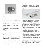
plasma arc bent anywhere from 5 to 15 degrees. (See Fig 4).
When you release the trigger, the arc will stop, but air will
continue to flow for about 30 seconds to cool the plasma
torch. When using the drag cutting tip, the highest cutting
efficiency is achieved by keeping the plasma cutting tip
perpendicular and in contact with the work surface putting
very little downforce on the plasma torch. If you move too
fast, sparks will shoot up and you will not cut all the way
through the work. If you are cutting correctly all the plasma
sparks will go beneath the panel you are cutting.

Fig. 4

5. When piercing a thicker sheet of steel (1/4” and greater)
hold the torch at approximately a 45 degree angle and
gradually roll the torch until it is perpendicular to the work
piece (See Fig. 5) If the torch is held perpendicular to the

work to start, there will be no where for the slag to flow, and it
will come straight up and damage the gas diffuser, cutting tip,
and electrode.

Fig. 5

WARNING: Never disassemble the cutting torch unless the
machine has been disconnected from its power supply.

Maintenance and Service

Always disconnect the machine from the main power source
before performing any maintenance or service work.

Consumable Parts:

1. Check nozzle and electrode often for excessive wear due to
cutting. The electrode will develop a pit in the center of it. When
the pit reaches approximately 1/16" deep, the electrode should
be replaced. (See Fig. 6) 

Fig. 6

Likewise, when the hole in the center of the cutting tip becomes
enlarged to approximately 1/16" in diameter, the cutting
efficiency will be reduced and the cutting tip should be
replaced. (See Fig. 7)

Содержание MicroCut 875S

Страница 1: ...Mi c r o C u t 8 7 5 S ...

Страница 2: ...you have purchased one of the most technologically advanced safest and economical plasma cutters available today The owner s manual has been designed to instruct you on the safe operation of your Micro Cut 875S If you read and follow the instructions in this manual your plasma cutter will provide you with years of trouble free operation If you fail to read and understand this manual as well as cor...

Страница 3: ...ED BY HTP Limited Warranty Subject to the terms and conditions hereof HTP warrants to its Distributor Dealer that all MicroCut 875S Plasma Cuffers furnished by HTP are free from defect in workmanship and material as of the time and place of delivery by HTP No warranty is made by HTP with respect to trade accessories or other items manufactured by others Such trade accessories and other items are s...

Страница 4: ...are also live when power is on Plasma arc cutting requires higher voltages than welding to start and maintain the arc 100 300 volts dc are common but also uses torches designed with safety interlock systems which turn off the machine when the shield cup is loosened or if tip touches electrode inside the nozzle Incorrectly installed or improperly grounded equipment is a hazard Do not touch live ele...

Страница 5: ...f ventilation is poor use an approved air supplied respirator Read the Material Safety Data Sheet MSDS and the manufacturer s instruction for metals to be cut coating and cleaners Work in a confined space only if it is well ventilated or while wearing an air supplied respirator Fumes from cutting and oxygen depletion can alter air quality causing injury or death Be sure the breathing air is safe D...

Страница 6: ...ece as close to the cut as possible About Pacemakers Pacemaker wearers consult your doctor first If cleared by your doctor then following the above procedures is recommended Never allow electrical contact between a plasma arc torch and cylinder Never cut on a pressurized cylinder Explosion will result Keep protective cap in place over valve except when cylinder is in use or connected for use Read ...

Страница 7: ...the filter needs to be discarded If you do not have a drier on your compressor we strongly recommend the HTP Max Dry Part 25310 This is a 3 stage filter which completely removes all oil and water from the air The first stage of the Max Dry removes the water which is present in the air The second stage of the filter removes any oil which may be in the air along with particulate down to 03 microns T...

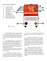
Страница 8: ...hat the air pressure is set to 70 psi for the correct operation of the machine with the air pressure flowing 3 THERMO SWITCH LIGHT if the duty cycle of the machine is exceeded 40 at 60 amps the yellow thermo switch light will be illuminated If this happens leave the machine on so the cooling fan will continue to run cooling the machine When the machine has cooled down the yellow light will go out ...

Страница 9: ...metal The Automatic mode is designated by the dashed line or the lower position We recommend leaving the machine in the manual setting unless there is some need to have the arc automatically ignite once contact is lost with the metal 10 PLASMA TORCH CONNECTION the central adapter block is where the plasma torch connects to the front of your Micro Cut 875S Your machine will not operate without the ...

Страница 10: ... cool the plasma torch When using the drag cutting tip the highest cutting efficiency is achieved by keeping the plasma cutting tip perpendicular and in contact with the work surface putting very little downforce on the plasma torch If you move too fast sparks will shoot up and you will not cut all the way through the work If you are cutting correctly all the plasma sparks will go beneath the pane...

Страница 11: ...ent cutting of circles and lines Fig 8 Circle Cutting Attachement 2 When cutting heavier gauge material up to the machine capability it is recommended to initiate the pilot arc off the edge of the material and dragging the pilot arc to the work piece 3 When making rust repairs it is possible to place the new metal over the rusted area and then cut your patch panel at the same time you cut the rust...

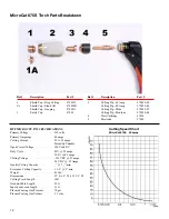
Страница 12: ... Speed Chart MicroCut 875S 40 amps HTP MICROCUT 875S SPECIFICATIONS Primary Voltage 230 volts Primary Amperage 40 amps Cutting Current 30 to 55 amps Infinitely Variable Open Circuit Voltage 320 Volts DC Duty Cycle 40 55 amps 100 45 amps Cutting Voltage 102 VDC 55 amps 96 VDC 45 Amps Quality Cutting Capacity _ 7 _ min Severance Cutting Capacity 1 1 8 3 min Weight 40 lbs Dimensions 22 L x 8 W x 11 1...

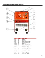
Страница 13: ...o Switch 660554 6 ID Label 660555 7 Torch Ground Label 20320 8 Female Ground Receptacle 22312 Male Ground Plug 22310 Ground Clamp Complete 61471 9 Female Torch Receptacle 660556 17 Decal Side Panel 62020 18 Side Panel 66028 19 Knob Amperage 660553 38 Front Panel Label MicroCut 875S Parts Breakdown part 1 ...

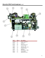
Страница 14: ...Illus Description 610889 10 PCB Primary Power 64393 11 Gas Solenoid Valve 64032 12 Pressure Safety Switch 650193 13 Control Transformer 64180 14 Fuse Holder 203335 2 15 Fuse MicroCut 875S Parts Breakdown part 2 ...

Страница 15: ...7 Choke Coil 66160 28 Gas Hose 61733 29 PCB Input Power 62018 30 Cabinet Base 64215 31 Thermoswitch 70 C 63053 32 Pressure Guage 63055 33 Regulator 64132 34 MicroSwitch Safety 62639 35 Center Panel 62022 36 Regulator Bracket MicroCut 875S Parts Breakdown part 3 ...

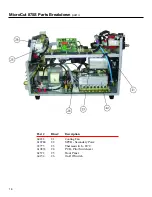
Страница 16: ...lus Description 64182 21 Cooling Fan 610784 22 SPCB Secondary Powe 65775 23 Thermoswitch 80 C 610833 24 PCB Pilot Switchover 62572 25 Front Panel 64154 26 On Off Switch MicroCut 875S Parts Breakdown part 4 16 ...

Страница 17: ...17 MicroCut 875S Wiring Diagram ...

Страница 18: ...18 ...

Страница 19: ...19 ...

Страница 20: ...20 ...

Отзывы: