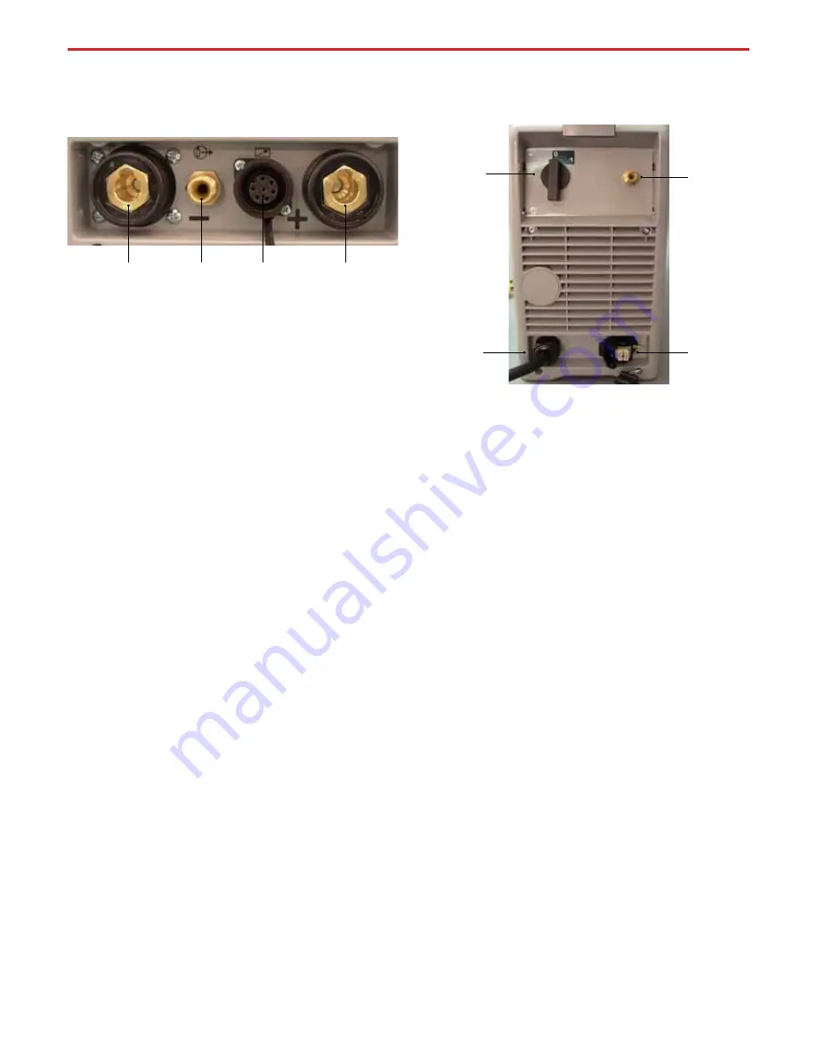
1. Negative Output Receptacle
When TIG welding, this is where the TIG Torch connects to your
Invertig 221 Welder. That’s right, we said the TIG Torch. This is
called straight polarity, with the torch negative and the work
positive. When using your Invertig Welder to TIG weld, all work
will be done in straight polarity.
When Stick Welding Direct Current Electrode Negative (DCEN),
the optional electrode holder will be plugged into the nega-
tive output receptacle. When Stick Welding Direct Current
Electrode Positive (DCEP), the ground cable will be plugged
into the negative output receptacle
To install a cable into the negative output receptacle, insert
the male end of the cable into the negative output receptacle
and twist clockwise until snug.
2. Gas Output Connection
T
his is where you connect the gas fitting from the TIG Torch.
The gas output is controlled by the solenoid valve, which is
mounted inside the welder.
3. 7
- Pin
Connection
T
he 7
-
pin connection is where your remote amperage control
would connect to your 221. This is also where you would con-
nect a momentary contact switch. Insert the connection into
the machine and twist the lock ring clockwise until snug.
I have found it is easiest to connect the remote first, the gas
second, and the positive and negative receptacles last.
4. Positive Output Receptacle
When TIG welding, this is where the ground cable connects to
the front of the TIG Adapter. That’s right, we said the ground
cable. This is called straight polarity, with the torch negative
and the work positive.
When Stick Welding Direct Current Electrode Negative (DCEN),
the ground cable will be plugged into the positive output
receptacle. When Stick Welding Direct Current Electrode
Positive (DCEP), the electrode holder will be plugged into
the positive output receptacle.
To install a cable into the positive output receptacle, insert
the male end of the cable into the positive output receptacle
and twist clockwise until snug.
1. On-Off Switch
This switch controls the input power to your Invertig Welder.
0 is off and 1 is on.
2. Gas Inlet Connection
Connect the female end of your gas hose to the inlet gas
connection and the male end of your gas hose to your flowmeter.
Shield Gas
TIG welding requires a shield gas of 100% Argon. A shield gas
is used to keep the surrounding atmosphere from coming in
contact with the molten weld puddle. The correct flow rate is
enough gas to shield the molten weld puddle and protect the
tungsten electrode. Any greater flow rate is a waste of shield
gas. Usually, the flow rate will be set anywhere between
15 and 30 cubic feet per hour (
CFH
).
Use a gas regulator such as HTP Part #12020 which is
compatible with Argon cylinders and has a barbed fitting
for the delivery hose.
Argon/helium mixtures can be used to increase penetration.
Argon/
h
elium mixes with high (more than 50%) helium
content will give you difficulties starting the arc, as well as arc
stability issues. As far as added headed into the weld puddle,
there are no real advantages to running mixtures with more
than 50% helium in AC mode.
If you will be welding thick
aluminum castings such as an aluminum cylinder head, ultra
high purity helium can be used. If you are welding thick
aluminum sections like cylinder heads and engine blocks, and
you do not want to preheat the part, you can weld these items
in DC using ultra high purity helium, to achieve maximum
penetration without pre-heating. Since there is no AC
cleaning cycle, it is important proper cleaning practices are
followed.
3. Input Power Cord
–
this is where the input power cord
passes through the rear of the cabinet.
4. 220V
& 110V/220V
Water
-
Cooler Connection
–
This is the
electrical
connection where a 220
V
or 110 V/220V
water
-
cooler will connect to your Invertig 221
/Invertig 221DV
. If you
have an Invertig 221DV, the water
-
cooler
will operate w
ith the
Invertig 221DV
connected to either 110V or 220V power.
The
water
-
cooler, like the Invertig 221 DV, auto senses the input
power voltage.
Figure 1
FRONT PANEl CONNECTIONS
REAR PANEl CONTROlS AND CONNECTIONS
Figure 2
1
2
4
3
1
2
3
4
5


