Included with DMA-1240
and DMA-1275
5
P
roduct
F
eatures
(1) Power cord
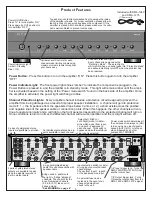
Power Button:
Press this button in to turn the amplifier “ON”. Press this button again to turn the amplifier
“OFF”.
Power Indicator Light:
The front power light shines “amber” to indicate the component is plugged in, the
Power Button is pressed in, and the amplifier is in stand-by mode. This light will remain amber until the ampli-
fier is activated based on the setting of the “Power mode switch” found on the back side of the amplifier. Once
the amplifier is activated, the power light will change to blue.
Channel Protection Lights:
Every amplifier channel includes a protection circuit designed to prevent the
amplifier from being damaged as a result of improper speaker installation. A channel will go into protection
mode if:
1.) the impedance from the speakers drops below 4 ohms, or 2.) a short exists across the positive
and negative lines of the speaker cable or connection points. When this happens, the other channels will con-
tinue to operate normally and a red light on the front panel corresponding to the protected channel will turn on.
Once conditions return to normal, the affected channel will resume operation and the red light will turn off.
Left
Right
Out 2
Out 1
In 2
In 1
1
2
3
Line In
4
5
6
7
8
9
10
11
12
Line In
1 2 Line
Bridged
L L+R R
L L+R R
L L+R R
L L+R R
L L+R R
L L+R R
L L+R R
L L+R R
L L+R R
L L+R R
L L+R R
L L+R R
On
Auto On
3-30V
AC/DC
Trigger In
AC 120V-60Hz
Fuse: T15A/250V
Power Consumption: 1200W
12V DC
Control
Out
T
rigger
1 2 Line
1 2 Line
1 2 Line
1 2 Line
1 2 Line
1 2 Line
1 2 Line
1 2 Line
1 2 Line
1 2 Line
1 2 Line
Line In
Line In
Line In
Line In
Bridged
Bridged
Bridged
Bridged
Bridged
DMA-1275
Power
Vol 1
Vol 2
Vol 3
Vol 4
Vol 5
Vol 6
Vol 7
Vol 8
Vol 9
Vol 10
Vol 11
Vol 12
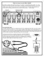
Top panel air vents allow unwanted heat to escape the inside
of the amplifier chassis. For proper ventilation, please allow at
least 5 inches of open air space above the component. If the
amplifier is placed within a cabinet, please make sure the cabi-
net is well ventilated to prevent overheating.
Power On/Off Button
Press “In” to turn amplifier “ON”
Press again (to OUT position) to
turn amplifier “OFF”
Power Indicator Light
Amber = Standby
Blue = ON
Channel Protection Lights
Every channel is designed with a
“Protection Mode”. These red lights
will turn ON when a channel goes into “Protection Mode”
and will automatically turn OFF when the problem has
been resolved.
Variable Level Controls for each
channel make limiting or balancing
maximum volume levels throughout
your home easy.
Left
Right
Out 2
Out 1
In 2
In 1
1
2
3
Line In
4
5
6
7
8
9
10
11
12
Line In
1 2 Line
Bridged
L L+R R
L L+R R
L L+R R
L L+R R
L L+R R
L L+R R
L L+R R
L L+R R
L L+R R
L L+R R
L L+R R
L L+R R
On
Auto On
3-30V
AC/DC
Trigger In
AC 120V-60Hz
Fuse: T15A/250V
Power Consumption: 1200W
12V DC
Control
Out
T
rigger
1 2 Line
1 2 Line
1 2 Line
1 2 Line
1 2 Line
1 2 Line
1 2 Line
1 2 Line
1 2 Line
1 2 Line
1 2 Line
Line In
Line In
Line In
Line In
Bridged
Bridged
Bridged
Bridged
Bridged
DMA-1275
Power
Vol 1
Vol 2
Vol 3
Vol 4
Vol 5
Vol 6
Vol 7
Vol 8
Vol 9
Vol 10
Vol 11
Vol 12
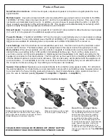
Select Left, Right, or
Left+Right (mono) to deter-
mine which signal from input
1 or input 2 is assigned to
each channel. This switch is
bypassed when the individual
Line input is selected.
Power mode switch determines if
the component is always on (ON),
turns on when an input signal is
sensed (AUTO-ON), or turns on
when triggered by another
component (TRIGGER).
1/8” Input trigger jack - Turns the
DMA-1240/DMA-1275 ON from
another component.
1/8” Output trigger jack - Turns
ON another component from the
DMA-1240’s/DMA-1275’s signal.
An individual gold-plated Line in-
put is available to each channel.
2 pairs of gold-plated stereo
inputs are available to all chan-
nels.
2 pairs of gold-plated stereo
outputs are available to pass
along the signals received in
the two stereo inputs.
5-way gold-plated binding
posts for solid connections with
speaker cable.
Input selection switch for deter-
mining input source that each
channel plays.
Choose from input 1, input 2,
or the dedicated Line input.
Bridge switch - postition to
the right to “bridge” adjacent
channels. The controls for the
Even Numbered channels
(2,4,6,8,10,12) take over in
bridged mode.
*See WARNING on page 4*
An external fuse can be
replaced in the event of an
unexpected electrical
shock to the unit.
Содержание DMA-1240
Страница 9: ...This Page Left Blank Intentionally...

