IN-4200
5
“ATTENTION“ -
En soulevant le siège, assurez-
vous que le tabouret reste dégagé de n’importe
quels meubles ou équipement. Autrement, la
force augmentante résultante peut endommager
les meubles, l’équipement ou le tabouret.
“NOTE”-
Après que la barre de soutien ait été
insérée dans l’appui arrière par instructions
d’assemblée (section 2.2), insérez la vis d’arrêt
dans le trou fileté dans l’extrémité de la barre de
soutien. Les #10-24 la vis principale que ronde de
machine de ¼ de X (numéro de la pièce 2037299)
est embarquée dans les pièces mettent en sac.
2
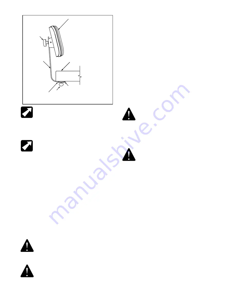
STOP SCREW
STOOL
SEAT
5
4
3
1
FIGURE 1
3. OPERATING INSTRUCTIONS
3.1. Seat Height Adjustment
3.1.1. A metered gas spring device provides for controlled
raising of the stool seat without load and controlled
lowering under load.
3.1.2 To raise the seat, support the body weight from the
floor and raise the lock handle lever located under the
seat. Allow the seat to rise to the desired position and
release the handle.
“NOTE”-
After support bar has been
inserted into back support per the assembly
instructions (section 2.2), insert stop screw
into threaded hole in end of support bar. The
#10-24 x ¼ Round Head Machine Screw (Part
Number 2037299) is shipped in the parts bag.
“CAUTION”-
When raising the seat, ensure
that the stool remains clear of any furniture or
equipment. Otherwise, the resulting raising force
may damage the furniture, equipment or stool.
3.2. Back Rest Adjustment
3.2.1. The back rest typical of Model 4246 can be
adjusted vertically and horizontally.
3.5.2. To adjust the back rest vertically, loosen the
black handwheel, (ltem 2, Figure 1), move the back
rest to the desired position and tighten the hand-
wheel.
3.2.3. To adjust the back rest horizontally, loosen the
thumbscrew (ltem 5, Figure 1), move the support bar,
Item 3, as desired and tighten the thumb screw
securely.
4. Replacement of Parts
4.1. When ordering replacement parts, please specify
the model number of the stool and the proper part
number from the following figures.
4.2. When ordering upholstered items, please specify
color.
“WARNING”-
The foot rest ring is
intended for lightweight foot support only
and is not intended for use as a step/
weight bearing support. lf repositioning
of the body is needed while seated, you
must insure both feet are firmly placed
on the floor before shifting your weight.
“VERTISSANT“-
l’anneau de repos
de pied est prévu pour l’appui léger de
pied seulement et n’est pas prévu pour
l’usage comme support de roulement
d’étape/poids. le replacement de LF du
corps est nécessaire tandis que posé,
vous doit assurer les deux pieds sont
fermement placés sur le plancher avant
de décaler votre poids.
Содержание Reliance 4200 Series
Страница 1: ...OWNERS MANUAL INSTALLATION AND OPERATING INSTRUCTIONS SERIES 4200 PNEUMATIC STOOLS EN FR ...
Страница 6: ...IN 4200 6 PAGE LEFT BLANK INTENTIONALLY ...
Страница 9: ...IN 4200 9 4 5 6 7 3 1 2 10 8 9 RELIANCE MODEL 4240 PNEUMATIC STOOL AND BASE PARTS FIGURE 2 ...
Страница 15: ...IN 4200 15 NOTES ...


