HRS DF40 Series Скачать руководство пользователя страница 9


TITLE

:     

DF40 Series Guideline


ETAD-H1015-00 


HIROSE ELECTRIC CO.,LTD.


PRODUCT

:


BOARD TO BOARD/FPC CONNECTOR, 

Pitch: 0.4mm, Width: 3.38mm,   

Stacking height: 1.5-4.0mm


PAGE:


9   

OF

    18 


Copyright© 2007 Hirose Electric Co., Ltd. All rights reserved. 


Mounting requirements 


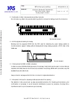
2.1 Metal mask design 

Recommended metal mask dimensions for receptacle (ex. 40 pos.) 


Recommended soldering paste amount: 0.0135 mm

(Per 1 Pad) 


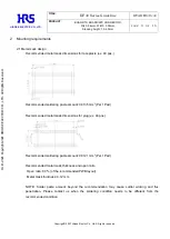
Recommended metal mask dimensions for plug (ex. 40 pos.) 


Recommended soldering paste amount: 0.0121 mm

(Per 1


Pad) 


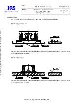
Recommended metal mask thickness and open ratio 

  Open ratio: 80 % (of the recommended PWB layout) 

  Metal mask thickness: 0.12 mm 


NOTE:  Solder  paste  amount  beyond  the  recommendation  may  cause  solder  wicking  and  flux 

penetration.  Please  contact  us  when  the  soldering  condition  needs  to  be  different  from  the 

recommended condition. 

Oct.1.2021 Copyright 2021 HIROSE ELECTRIC CO., LTD. All Rights Reserved.

Содержание DF40 Series

Страница 1: ...OF 18 Copyright 2007 Hirose Electric Co Ltd All rights reserved DF40 Series Guideline ETAD H1015 00 Approver WR FUKUCHI 20210331 Checker TS MIYAZAKI 20210330 Designer PAN YIWEI 20210330 REVISIONS DIS...

Страница 2: ...Selection of connector mounting machine and notice for mounting 6 1 2 PWB requirements 7 1 2 1 Recommended PWB pattern 7 1 2 2 PWB pad layout and connector location 8 1 2 3 PWB designing 8 1 2 4 FPC...

Страница 3: ...s applied to contacts during un mating process when this product is mounted onto low rigidity or thin FPC Under the circumstances mount plug connector of which retention force is higher than the other...

Страница 4: ...td All rights reserved 1 1 3 FPC fixing For FPC alignment by guide posts do not disturb FPC flexibility Design without flexibility of FPC could apply direct stress to the connector by drop impact etc...

Страница 5: ...ctors on one board receptacle and plug the following mounting accuracy is required As mentioned above very tight tolerances are required It is impossible to satisfy this tolerance in consideration of...

Страница 6: ...FPC side to the PWB side 1 1 7 Precautions for PWB to PWB connection In order to connect PWB to PWB precision of necessary components and mounter or screw fitting is required and direct stress to the...

Страница 7: ...se Electric Co Ltd All rights reserved 1 2 PWB requirements 1 2 1 Recommended PWB pattern Recommended PWB pad layout for receptacle ex 40 pos Patterning of different signals is unacceptable on the are...

Страница 8: ...yout optimum retention force can be obtained between connector and PWB Solder wicking and flux penetration could occur by applying different PWB layout from the recommended Please contact us for the d...

Страница 9: ...soldering paste amount 0 0135 mm3 Per 1 Pad Recommended metal mask dimensions for plug ex 40 pos Recommended soldering paste amount 0 0121 mm3 Per 1 Pad Recommended metal mask thickness and open rati...

Страница 10: ...dgment of fillet forming quality check side fillet forming as an indication Fillet forming on receptacle Recommended condition is that fillet thickness is one third of contact thickness 0 13 mm or mor...

Страница 11: ...temperature at the connector lead area 2 Reflow cycles Up to 2 cycles of reflow soldering are acceptable under the recommended reflow profile of DF40 Series 3 Reflow heating method and condition Far...

Страница 12: ...act lead The raise of solder paste may affect on distance of PWBs or performance of spring contact of the receptacle Repairing condition Soldering iron 350 C 3 seconds MAX Notice Do not apply stress t...

Страница 13: ...r is led into the mating pair by self alignment function 3 Once aligned the connector pair does not move back and forth and around as they are located in a parallel position Mate the connectors comple...

Страница 14: ...o unmate the connector in vertical direction 2 When vertical removal is difficult lift up either side of longitudinal contact pitch direction Do not unmate the connector in connector width direction o...

Страница 15: ...Co Ltd All rights reserved Failure caused by removing the connector in the width direction 3 Check the rigidity of the FPC for unmating operation prior to your production otherwise solder breakage an...

Страница 16: ...Width 3 38mm Stacking height 1 5 4 0mm PAGE 16 OF 18 Copyright 2007 Hirose Electric Co Ltd All rights reserved 4 PWB and solder paste applied for evaluation test 4 1 PWB applied for evaluation test G...

Страница 17: ...g height 1 5 4 0mm PAGE 17 OF 18 Copyright 2007 Hirose Electric Co Ltd All rights reserved Glass epoxy board for plug FPC for receptacle 4 2 Solder paste applied for evaluation test Lead free solder p...

Страница 18: ...rred on the housing surface due to high heat during reflow In order to prevent this problem avoid storing connectors under humid condition For long term storage keep them at humidity manageable place...

Отзывы: