background image


46 

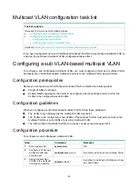
Configuring a port-based multicast VLAN 

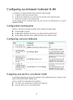
To configure a port-based multicast VLAN, perform the following steps: 

1. 

Configure a VLAN as the multicast VLAN. 

2. 

Configure the attributes for user ports that are connected to the multicast receivers. 

3. 

Assign the user ports to the multicast VLAN. 

You can assign a port to a multicast VLAN only when the port is an Ethernet port or a Layer 2 
aggregate interface. 

Configuration prerequisites 

Before you configure a port-based multicast VLAN, complete the following tasks: 


Create VLANs as required. 


Enable IGMP snooping for the VLAN to be configured as the multicast VLAN. 


Enable IGMP snooping for all the VLANs that contain the multicast receivers. 

Configuring user port attributes 

Step Command 

Remarks 

1. 

Enter system view. 

system-view 

N/A 

2. 

Enter interface view. 

interface


interface-type interface-number

N/A 

3. 

Configure the link 
type of the user port 
as hybrid. 

port link-type hybrid 

The default setting is 

access

For more information about this 
command, see 

Layer 2—LAN 

Switching Command Reference.


4. 

Specify the PVID of 
the current user port 
as the VLAN to 
which the user port 
belongs. 

port hybrid pvid vlan


vlan-id 

By default, the PVID for a hybrid 
port is VLAN 1. 

For more information about this 
command, see 

Layer 2—LAN 

Switching Command Reference.


5. 

Configure the 
current user port to 
permit the multicast 
VLAN and to untag 
the packets. 

port hybrid vlan


vlan-id-list


untagged 

By default, a hybrid port permits 
only VLAN 1. 

For more information about this 
command, see 

Layer 2—LAN 

Switching Command Reference.


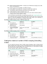
Assigning user ports to a multicast VLAN 

You can either assign the user ports to the multicast VLAN in multicast VLAN view, or assign the user 
ports to the multicast VLAN in interface view.  

When you perform this task, follow these guidelines: 


The VLAN to be configured as a multicast VLAN must exist. 


A port can belong to only one multicast VLAN. 

Содержание FlexNetwork 5130 EI Series

Страница 1: ...HPE FlexNetwork 5130 EI Switch Series IP Multicast Configuration Guide Part number 5998 5477s Software version Release 3111P02 and later Document version 6W101 20161010 ...

Страница 2: ... and 12 212 Commercial Computer Software Computer Software Documentation and Technical Data for Commercial Items are licensed to the U S Government under vendor s standard commercial license Links to third party websites take you outside the Hewlett Packard Enterprise website Hewlett Packard Enterprise has no control over and is not responsible for information outside the Hewlett Packard Enterpris...

Страница 3: ...ping querier 21 Configuration prerequisites 21 Enabling the IGMP snooping querier 21 Configuring parameters for IGMP queries and responses 22 Configuring parameters for IGMP messages 22 Configuration prerequisites 23 Configuring source IP addresses for IGMP messages 23 Setting the 802 1p priority for IGMP messages 24 Configuring IGMP snooping policies 24 Configuring a multicast group policy 24 Con...

Страница 4: ... 60 Setting aging timers for dynamic ports 60 Configuring static ports 60 Configuring a port as a simulated member host 61 Enabling fast leave processing 61 Disabling a port from becoming a dynamic router port 62 Configuring the MLD snooping querier 63 Configuration prerequisites 63 Enabling the MLD snooping querier 63 Configuring parameters for MLD queries and responses 63 Configuring parameters ...

Страница 5: ...multicast VLAN 88 Configuration prerequisites 88 Configuring user port attributes 88 Assigning user ports to an IPv6 multicast VLAN 88 Setting the maximum number of IPv6 multicast VLAN forwarding entries 89 Displaying and maintaining IPv6 multicast VLANs 89 IPv6 multicast VLAN configuration examples 90 Sub VLAN based IPv6 multicast VLAN configuration example 90 Port based IPv6 multicast VLAN confi...

Страница 6: ...ast Unicast In unicast transmission the information source must send a separate copy of information to each host that needs the information Figure 1 Unicast transmission In Figure 1 Host B Host D and Host E need the information A separate transmission channel must be established from the information source to each of these hosts In unicast transmission the traffic transmitted over the network is p...

Страница 7: ...s broadcasting to hosts that do not need the information also causes traffic flooding on the same subnet Broadcast is not as efficient as multicast for sending data to groups of hosts Multicast Multicast provides point to multipoint data transmissions with the minimum network consumption When some hosts on the network need multicast information the information sender or multicast source sends only...

Страница 8: ...ined to the same subnet Multicast features A multicast group is a multicast receiver set identified by an IP multicast address Hosts must join a multicast group to become members of the multicast group before they receive the multicast data addressed to that multicast group Typically a multicast source does not need to join a multicast group A multicast source is an information sender It can send ...

Страница 9: ...st source S sends to multicast group G S represents a specific multicast source and G represents a specific multicast group Multicast benefits and applications Multicast benefits Enhanced efficiency Reduces the processor load of information source servers and network devices Optimal performance Reduces redundant traffic Distributed application Enables point to multipoint applications at the price ...

Страница 10: ...receivers exist on the network Host registration Where is the multicast source that will provide data to the receivers Multicast source discovery How is the information transmitted to the receivers Multicast routing IP multicast is an end to end service The multicast architecture involves the following parts Addressing mechanism A multicast source sends information to a group of receivers through ...

Страница 11: ...chanism for assigning multicast addresses between different ASs By filling an AS number into the middle two bytes of 233 0 0 0 you get 255 multicast addresses for that AS For more information see RFC 2770 Table 3 Common permanent multicast group addresses Address Description 224 0 0 1 All systems on this subnet including hosts and routers 224 0 0 2 All multicast routers on this subnet 224 0 0 3 Un...

Страница 12: ...his address is an IPv6 multicast address not based on a unicast prefix When set to 1 this address is an IPv6 multicast address based on a unicast prefix The T bit must also be set to 1 T When set to 0 this address is an IPv6 multicast address permanently assigned by IANA When set to 1 this address is a transient or dynamically assigned IPv6 multicast address Scope The Scope field contains four bit...

Страница 13: ...ing five bits of the IPv4 multicast address are lost As a result 32 IPv4 multicast addresses are mapped to the same IPv4 multicast MAC address Therefore a device might receive unwanted multicast data at Layer 2 processing which needs to be filtered by the upper layer IPv6 multicast MAC addresses As defined by IANA the most significant 16 bits of an IPv6 multicast MAC address are 0x3333 The least s...

Страница 14: ... and multicast routing protocols Figure 8 Positions of Layer 3 multicast protocols Multicast group management protocols Internet Group Management Protocol IGMP and Multicast Listener Discovery MLD protocol are multicast group management protocols Typically they run between hosts and Layer 3 multicast devices that directly connect to the hosts to establish and maintain the multicast group membershi...

Страница 15: ...nooping and MLD snooping run on Layer 2 devices as multicast constraining mechanisms to improve multicast forwarding efficiency They generate Layer 2 multicast forwarding tables by listening to IGMP or MLD messages exchanged between the hosts and Layer 3 multicast devices This effectively controls the flooding of multicast data in Layer 2 networks PIM snooping and IPv6 PIM snooping PIM snooping an...

Страница 16: ... interfaces Compared to a unicast model a multicast model is more complex in the following aspects To ensure multicast packet transmission in the network different routing tables are used for multicast forwarding These routing tables include unicast routing tables routing tables for multicast for example the MBGP routing table and static multicast routing tables To process the same multicast infor...

Страница 17: ...own in Figure 10 when IGMP snooping is not enabled the Layer 2 device floods multicast packets to all hosts When IGMP snooping is enabled the Layer 2 device forwards multicast packets of known multicast groups to only the receivers Figure 10 Multicast packet transmission without and with IGMP snooping Basic IGMP snooping concepts IGMP snooping related ports As shown in Figure 11 IGMP snooping runs...

Страница 18: ...uter ports and member ports NOTE When IGMP snooping is enabled all ports that receive PIM hello messages or IGMP general queries with the source addresses other than 0 0 0 0 are considered dynamic router ports Aging timers for dynamic ports in IGMP snooping The following are aging timers for dynamic ports in IGMP snooping Dynamic router port aging timer The Layer 2 device starts this timer for a p...

Страница 19: ... receiving port is not in the forwarding entry the Layer 2 device adds the port as an outgoing interface to the forwarding entry It also marks the receiving port as a dynamic member port and starts an aging timer for the port If a match is found and the receiving port is in the forwarding entry the Layer 2 device restarts the aging timer for the port In an application with a multicast group policy...

Страница 20: ...ves an IGMP report before the aging timer expires the Layer 2 device restarts the aging timer for the port If the port does not receive an IGMP report when the aging timer expires the Layer 2 device removes the port from the forwarding entry for the multicast group Protocols and standards RFC 4541 Considerations for Internet Group Management Protocol IGMP and Multicast Listener Discovery MLD Snoop...

Страница 21: ...uery interval Determine the maximum response time for IGMP general queries Enabling IGMP snooping When you enable IGMP snooping follow these guidelines You must enable IGMP snooping globally before you enable it for a VLAN IGMP snooping for a VLAN works only on the member ports in that VLAN You can enable IGMP snooping for the specified VLANs in IGMP snooping view or for a VLAN in VLAN view For a ...

Страница 22: ...ew or for a VLAN in VLAN view For a VLAN the configuration in VLAN view has the same priority as the configuration in IGMP snooping view and the most recent configuration takes effect To specify an IGMP snooping version for a VLAN in IGMP snooping view Step Command Remarks 1 Enter system view system view N A 2 Enable IGMP snooping globally and enter IGMP snooping view igmp snooping N A 3 Specify a...

Страница 23: ...er port receives a PIMv2 hello message the aging timer value for the port is specified by the hello message In this case the router aging time or igmp snooping router aging time command does not take effect on the port You can set the timers globally for all VLANs in IGMP snooping view or for a VLAN in VLAN view For a VLAN the VLAN specific configuration takes priority over the global configuratio...

Страница 24: ...Layer 2 Ethernet interface view or Layer 2 aggregate interface view interface interface type interface number N A 3 Configure the port as a static port Configure the port as a static member port igmp snooping static group group address source ip source address vlan vlan id Configure the port as a static router port igmp snooping static router port vlan vlan id By default a port is not a static mem...

Страница 25: ...g view igmp snooping N A 3 Enable fast leave processing globally fast leave vlan vlan list By default fast leave processing is disabled globally Enabling fast leave processing on a port Step Command Remarks 1 Enter system view system view N A 2 Enter Layer 2 Ethernet interface view or Layer 2 aggregate interface view interface interface type interface number N A 3 Enable fast leave processing on t...

Страница 26: ...MP snooping for the VLAN Determine the IGMP general query interval Determine the IGMP last member query interval Determine the maximum response time for IGMP general queries Enabling the IGMP snooping querier This feature enables the switch to periodically send IGMP general queries to establish and maintain multicast forwarding entries at the data link Layer You can configure an IGMP snooping quer...

Страница 27: ...interval interval command You can configure the parameters globally for all VLANs in IGMP snooping view or for a VLAN in VLAN view For a VLAN the VLAN specific configuration takes priority over the global configuration Configuring the global parameters for IGMP queries and responses Step Command Remarks 1 Enter system view system view N A 2 Enter IGMP snooping view igmp snooping N A 3 Set the maxi...

Страница 28: ...esses for IGMP messages in a VLAN Step Command Remarks 1 Enter system view system view N A 2 Enter VLAN view vlan vlan id N A 3 Configure the source IP address for IGMP general queries igmp snooping general query source ip ip address The default setting is the IP address of the current VLAN interface If the current VLAN interface does not have an IP address the source IP address is 0 0 0 0 4 Confi...

Страница 29: ...mmand Remarks 1 Enter system view system view N A 2 Enter VLAN view vlan vlan id N A 3 Set the 802 1p priority for IGMP messages in the VLAN igmp snooping dot1p priority priority number The default setting is 0 Configuring IGMP snooping policies Before you configure IGMP snooping policies complete the following tasks Enable IGMP snooping for the VLAN Determine the ACLs to be used by multicast grou...

Страница 30: ... only to multicast receivers You can enable this feature for the specified ports in IGMP snooping view or for a port in interface view For a port the configuration in interface view has the same priority as the configuration in IGMP snooping view and the most recent configuration takes effect Configuring multicast source port filtering globally Step Command Remarks 1 Enter system view system view ...

Страница 31: ... groups on a port to regulate the port traffic When you set the maximum number of multicast groups on a port follow these guidelines This configuration takes effect only on the multicast groups that a port joins dynamically If the number of multicast groups on a port exceeds the limit the system removes all the forwarding entries related to that port from the IGMP snooping forwarding table The rec...

Страница 32: ...a port Step Command Remarks 1 Enter system view system view N A 2 Enter Layer 2 Ethernet interface view or Layer 2 aggregate interface view interface interface type interface number N A 3 Enable multicast group replacement feature on a port igmp snooping overflow replace vlan vlan list By default the multicast group replacement feature is disabled on a port Displaying and maintaining IGMP snooping...

Страница 33: ... group group address source address all vlan vlan id Delete dynamic router ports reset igmp snooping router port all vlan vlan id Clear statistics for the IGMP messages learned through IGMP snooping reset igmp snooping statistics IGMP snooping configuration examples Group policy and simulated joining configuration example for VLANs Network requirements As shown in Figure 12 Router A runs IGMPv2 an...

Страница 34: ... GigabitEthernet1 0 2 pim dm RouterA GigabitEthernet1 0 2 quit 3 Configure Switch A Enable IGMP snooping globally SwitchA system view SwitchA igmp snooping SwitchA igmp snooping quit Create VLAN 100 and assign GigabitEthernet 1 0 1 through GigabitEthernet 1 0 4 to the VLAN SwitchA vlan 100 SwitchA vlan100 port gigabitethernet 1 0 1 to gigabitethernet 1 0 4 Enable IGMP snooping and enable dropping ...

Страница 35: ...ping group vlan 100 Total 1 entries VLAN 100 Total 1 entries 0 0 0 0 224 1 1 1 Host slots 0 in total Host ports 2 in total GE1 0 3 00 03 23 GE1 0 4 00 04 10 The output shows the following information Host A and Host B have joined multicast group 224 1 1 1 through the member ports GigabitEthernet 1 0 4 and GigabitEthernet 1 0 3 on Switch A respectively Host A and Host B have failed to join multicas...

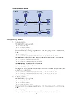
Страница 36: ...tch A Switch C when the path of Switch A Switch B Switch C is blocked Figure 13 Network diagram Configuration procedure 1 Assign an IP address and subnet mask to each interface as shown in Figure 13 Details not shown 2 On Router A Enable IP multicast routing RouterA system view RouterA multicast routing RouterA mrib quit Enable IGMP on GigabitEthernet 1 0 1 RouterA interface gigabitethernet 1 0 1 ...

Страница 37: ... 100 SwitchB vlan100 igmp snooping enable SwitchB vlan100 quit 5 Configure Switch C Enable IGMP snooping globally SwitchC system view SwitchC igmp snooping SwitchC igmp snooping quit Create VLAN 100 and assign GigabitEthernet 1 0 1 through GigabitEthernet 1 0 5 to the VLAN SwitchC vlan 100 SwitchC vlan100 port gigabitethernet 1 0 1 to gigabitethernet 1 0 5 Enable IGMP snooping for VLAN 100 SwitchC...

Страница 38: ...ple Network requirements As shown in Figure 14 The network is a Layer 2 only network Source 1 and Source 2 send multicast data to multicast groups 224 1 1 1 and 225 1 1 1 respectively Host A and Host C are receivers of multicast group 224 1 1 1 and Host B and Host D are receivers of multicast group 225 1 1 1 All receiver hosts run IGMPv2 and all switches run IGMPv2 snooping Switch A which is close...

Страница 39: ...ure the source IP address of IGMP general queries and IGMP group specific queries as 192 168 1 1 in VLAN 100 SwitchA vlan100 igmp snooping general query source ip 192 168 1 1 SwitchA vlan100 igmp snooping special query source ip 192 168 1 1 SwitchA vlan100 quit 2 Configure Switch B Enable IGMP snooping globally SwitchB system view SwitchB igmp snooping SwitchB igmp snooping quit Create VLAN 100 an...

Страница 40: ...net 1 0 1 and GigabitEthernet 1 0 2 to the VLAN SwitchD vlan 100 SwitchD vlan100 port gigabitethernet 1 0 1 to gigabitethernet 1 0 2 Enable IGMP snooping and enable dropping unknown multicast packets for VLAN 100 SwitchD vlan100 igmp snooping enable SwitchD vlan100 igmp snooping drop unknown SwitchD vlan100 quit Verifying the configuration Display statistics for IGMP messages learned through IGMP ...

Страница 41: ...ard Enterprise Support Multicast group policy does not work Symptom Hosts can receive multicast data from multicast groups that are not permitted by the multicast group policy Solution To resolve the problem 1 Use the display acl command to verify that the configured ACL meets the multicast group policy requirements 2 Use the display this command in IGMP snooping view or in an interface view to ve...

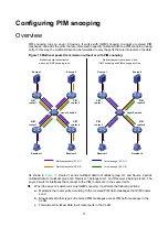
Страница 42: ...that connect to the PIM routers are in the same VLAN When the Layer 2 switch runs only IGMP snooping it performs the following actions a Maintains the router ports according to the received PIM hello messages that PIM routers send b Broadcasts all other types of received PIM messages except PIM hello messages in the VLAN c Forwards all multicast data to all router ports in the VLAN Multicast packe...

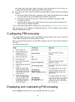
Страница 43: ...ks only on the member interfaces of the VLAN To configure PIM snooping Step Command Remarks 1 Enter system view system view N A 2 Enable IGMP snooping globally and enter IGMP snooping view igmp snooping By default IGMP snooping is disabled 3 Return to system view quit N A 4 Enter VLAN view vlan vlan id N A 5 Enable IGMP snooping for the VLAN igmp snooping enable By default IGMP snooping is disable...

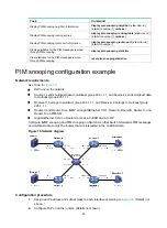
Страница 44: ...own in Figure 16 RIP runs on the network Source 1 sends multicast data to multicast group 224 1 1 1 and Source 2 sends multicast data to multicast group 225 1 1 1 Receiver 1 belongs to multicast group 224 1 1 1 and Receiver 2 belongs to multicast group 225 1 1 1 Router C and Router D run IGMP on GigabitEthernet 1 0 1 Router A Router B Router C and Router D run PIM SM GigabitEthernet 1 0 2 on Route...

Страница 45: ...g RouterB mrib quit Enable PIM SM on each interface RouterB interface gigabitethernet 1 0 1 RouterB GigabitEthernet1 0 1 pim sm RouterB GigabitEthernet1 0 1 quit RouterB interface gigabitethernet 1 0 2 RouterB GigabitEthernet1 0 2 pim sm RouterB GigabitEthernet1 0 2 quit 5 Configure Router C Enable IP multicast routing RouterC system view RouterC multicast routing RouterC mrib quit Enable IGMP on ...

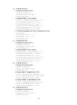
Страница 46: ... gigabitethernet 1 0 4 SwitchA vlan100 igmp snooping enable SwitchA vlan100 pim snooping enable SwitchA vlan100 quit Verifying the configuration On Switch A display information about PIM snooping neighbors for VLAN 100 SwitchA display pim snooping neighbor vlan 100 Total 4 neighbors VLAN 100 Total 4 neighbors 10 1 1 1 Slots 0 in total Ports 1 in total GE1 0 1 00 32 43 10 1 1 2 Slots 0 in total Por...

Страница 47: ...data intended for multicast group 224 1 1 1 to only Router C Switch A will forward the multicast data intended for multicast group 225 1 1 1 to only Router D Troubleshooting PIM snooping PIM snooping does not work on a Layer 2 device Symptom PIM snooping does not work on a Layer 2 device Solution 1 Use the display current configuration command to display information about IGMP snooping and PIM sno...

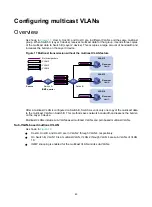
Страница 48: ...witch B Switch A sends only one copy of the multicast data to the multicast VLAN on Switch B This method saves network bandwidth and lessens the burden on the Layer 3 device Multicast VLANs include sub VLAN based multicast VLANs and port based multicast VLANs Sub VLAN based multicast VLAN As shown in Figure 18 Host A Host B and Host C are in VLAN 2 through VLAN 4 respectively On Switch B VLAN 10 i...

Страница 49: ...On Switch B VLAN 10 is a multicast VLAN All the user ports ports with attached hosts are hybrid ports and assigned to VLAN 10 IGMP snooping is enabled for the multicast VLAN and VLAN 2 through VLAN 4 Figure 19 Port based multicast VLAN IGMP snooping manages the router ports and member ports in the multicast VLAN When Switch B receives an IGMP message from a user port it tags the message with the m...

Страница 50: ...sub VLAN based multicast VLAN complete the following tasks Create VLANs as required Enable IGMP snooping for the VLAN to be configured as the multicast VLAN and for the VLANs to be configured as sub VLANs Configuration guidelines When you configure a sub VLAN based multicast VLAN follow these guidelines The VLAN to be configured as the multicast VLAN must exist The VLANs to be configured as sub VL...

Страница 51: ...N A 3 Configure the link type of the user port as hybrid port link type hybrid The default setting is access For more information about this command see Layer 2 LAN Switching Command Reference 4 Specify the PVID of the current user port as the VLAN to which the user port belongs port hybrid pvid vlan vlan id By default the PVID for a hybrid port is VLAN 1 For more information about this command se...

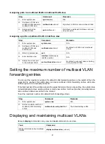
Страница 52: ...ot belong to any multicast VLAN Setting the maximum number of multicast VLAN forwarding entries You can set the maximum number of multicast VLAN forwarding entries on the switch When the upper limit is reached the switch does not create multicast VLAN forwarding entries until some entries age out or are manually removed If the total number of the entries exceeds the upper limit value that you are ...

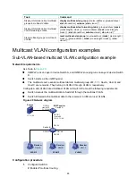
Страница 53: ... As shown in Figure 20 IGMPv2 runs on Layer 3 device Switch A and IGMPv2 snooping runs on Layer 2 device Switch B Switch A acts as the IGMP querier The multicast source sends multicast data to multicast group 224 1 1 1 Host A Host B and Host C are receivers They belong to VLAN 2 through VLAN 4 respectively Configure a sub VLAN based multicast VLAN on Switch B to meet the following requirements Swi...

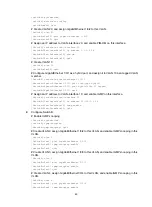
Страница 54: ...rnet1 0 1 quit Assign an IP address to VLAN interface 10 and enable IGMP on this interface SwitchA interface vlan interface 10 SwitchA Vlan interface10 ip address 10 110 1 1 24 SwitchA Vlan interface10 igmp enable SwitchA Vlan interface10 quit 2 Configure Switch B Enable IGMP snooping SwitchB system view SwitchB igmp snooping SwitchB igmp snooping quit Create VLAN 2 assign GigabitEthernet 1 0 2 to...

Страница 55: ...isplay multicast vlan Total 1 multicast VLANs Multicast VLAN 10 Sub VLAN list 3 in total 2 4 Port list 0 in total Display information about multicast groups in multicast VLANs on Switch B SwitchB display multicast vlan group Total 1 entries Multicast VLAN 10 Total 1 entries 0 0 0 0 224 1 1 1 Sub VLANs 3 in total VLAN 2 VLAN 3 VLAN 4 The output shows that multicast group 224 1 1 1 belongs to multic...

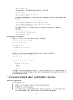
Страница 56: ...DM on this interface SwitchA interface vlan interface 20 SwitchA Vlan interface20 ip address 1 1 1 2 24 SwitchA Vlan interface20 pim dm SwitchA Vlan interface20 quit Create VLAN 10 and assign GigabitEthernet 1 0 1 to the VLAN SwitchA vlan 10 SwitchA vlan10 port gigabitethernet 1 0 1 SwitchA vlan10 quit Assign an IP address to VLAN interface 10 and enable IGMP on this interface SwitchA interface vl...

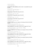
Страница 57: ...nd VLAN 10 as an untagged VLAN member SwitchB GigabitEthernet1 0 2 port hybrid vlan 2 untagged SwitchB GigabitEthernet1 0 2 port hybrid vlan 10 untagged SwitchB GigabitEthernet1 0 2 quit Configure GigabitEthernet 1 0 3 as a hybrid port and configure VLAN 3 as the PVID of the hybrid port SwitchB interface gigabitethernet 1 0 3 SwitchB GigabitEthernet1 0 3 port link type hybrid SwitchB GigabitEthern...

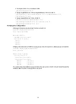
Страница 58: ...lay information about multicast VLANs on Switch B SwitchB display multicast vlan Total 1 multicast VLANs Multicast VLAN 10 Sub VLAN list 0 in total Port list 0 in total GE1 0 2 GE1 0 3 GE1 0 4 Display information about IGMP snooping group entries for dynamic multicast groups on Switch B SwitchB display igmp snooping group Total 1 entries VLAN 2 Total 1 entries 0 0 0 0 224 1 1 1 Host slots 0 in tot...

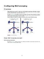
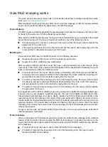
Страница 59: ...ure 22 when MLD snooping is not enabled the Layer 2 device floods IPv6 multicast packets to all hosts When MLD snooping is enabled the Layer 2 device forwards multicast packets of known IPv6 multicast groups to only the receivers Figure 22 Multicast packet transmission processes without and with MLD snooping Basic MLD snooping concepts MLD snooping related ports As shown in Figure 23 MLD snooping ...

Страница 60: ...dynamic router ports and member ports NOTE When MLD snooping is enabled all ports that receive IPv6 PIM hello messages or MLD general queries with a source IP address other than 0 0 are considered dynamic router ports Aging timers for dynamic ports in MLD snooping The following are aging timers for dynamic ports in MLD snooping Dynamic router port aging timer The Layer 2 device starts this timer f...

Страница 61: ...ving port as a dynamic member port and starts an aging timer for the port If a match is found but the receiving port is not in the forwarding entry the Layer 2 device adds the receiving port as an outgoing interface to the forwarding entry It also marks the receiving port as a dynamic member port and starts an aging timer for the port If a match is found and the receiving port is in the forwarding...

Страница 62: ...warding entry for the IPv6 multicast group Protocols and standards RFC 4541 Considerations for Internet Group Management Protocol IGMP and Multicast Listener Discovery MLD Snooping Switches MLD snooping configuration task list Tasks at a glance Configuring basic MLD snooping features Required Enabling MLD snooping Optional Specifying an MLD snooping version Optional Setting the maximum number of M...

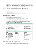
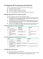
Страница 63: ...MLD snooping for the specified VLANs in MLD snooping view or for a VLAN in VLAN view For a VLAN the configuration in VLAN interface has the same priority as the configuration in MLD snooping view and the most recent configuration takes effect To enable MLD snooping for a VLAN in MLD snooping view Step Command Remarks 1 Enter system view system view N A 2 Enable MLD snooping globally and enter MLD ...

Страница 64: ...ystem view N A 2 Enable MLD snooping globally and enter MLD snooping view mld snooping N A 3 Specify an MLD snooping version for the specified VLANs version version number vlan vlan list The default setting is 1 Specifying an MLD snooping version in VLAN view Step Command Remarks 1 Enter system view system view N A 2 Enter VLAN view vlan vlan id N A 3 Specify an MLD snooping version for the VLAN m...

Страница 65: ... VLAN in VLAN view For a VLAN the VLAN specific configuration takes priority over the global configuration Setting the aging timers for dynamic ports globally Step Command Remarks 1 Enter system view system view N A 2 Enter MLD snooping view mld snooping N A 3 Set the aging timer for dynamic router ports globally router aging time interval The default setting is 260 seconds 4 Set the aging timer f...

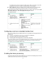
Страница 66: ...t a port is not a static member port or a static router port Configuring a port as a simulated member host When a port is configured as a simulated member host it is equivalent to an independent host in the following ways It sends an unsolicited MLD report when you complete the configuration It responds to MLD general queries with MLD reports It sends an MLD done message when you remove the config...

Страница 67: ... snooping fast leave vlan vlan list By default fast leave processing is disabled on a port Disabling a port from becoming a dynamic router port A receiver host might send MLD general queries or IPv6 PIM hello messages for testing purposes On the Layer 2 device the port that receives either of the messages becomes a dynamic router port Before the aging timer for the port expires the following probl...

Страница 68: ... multicast network that runs MLD An MLD snooping querier does not participate in MLD querier elections However it might affect MLD querier elections if it sends MLD general queries with a low source IPv6 address To enable the MLD snooping querier for a VLAN Step Command Remarks 1 Enter system view system view N A 2 Enter VLAN view vlan vlan id N A 3 Enable the MLD snooping querier for the VLAN mld...

Страница 69: ... listener query interval interval The default setting is 1 second Configuring parameters for MLD queries and responses in a VLAN Step Command Remarks 1 Enter system view system view N A 2 Enter VLAN view vlan vlan id N A 3 Set the MLD general query interval for the VLAN mld snooping query interval interval The default setting is 125 seconds 4 Set the maximum response time for MLD general queries i...

Страница 70: ...eries is one of the following The source address of MLD general queries if the MLD snooping querier has received MLD general queries The IPv6 link local address of the current VLAN interface if the MLD snooping querier does not receive an MLD general query FE80 02FF FFFF FE00 000 1 if the MLD snooping querier does not receive an MLD general query and the current VLAN interface does not have an IPv...

Страница 71: ... MLD messages in the VLAN mld snooping dot1p priority priority number The default setting is 0 Configuring MLD snooping policies Before you configure MLD snooping policies complete the following tasks Enable MLD snooping for the VLAN Determine the ACLs to be used by the IPv6 multicast group policies Determine the maximum number of IPv6 multicast groups that a port can join Configuring an IPv6 mult...

Страница 72: ...source port filtering for the specified ports in MLD snooping view or for a port in interface view For a port the configuration in interface view has the same priority as the configuration in MLD snooping view and the most recent configuration takes effect Enabling IPv6 multicast source port filtering in MLD snooping view Step Command Remarks 1 Enter system view system view N A 2 Enter MLD snoopin...

Страница 73: ...umber of IPv6 multicast groups on a port You can set the maximum number of IPv6 multicast groups on a port to regulate the port traffic Configuration restrictions and guidelines When you set the maximum number of IPv6 multicast groups on a port follow these restrictions and guidelines This configuration takes effect only on the IPv6 multicast groups that the port joins dynamically If the number of...

Страница 74: ...t By default the IPv6 multicast group replacement feature is disabled Enabling IPv6 multicast group replacement on a port Step Command Remarks 1 Enter system view system view N A 2 Enter Layer 2 Ethernet interface view or Layer 2 aggregate interface view interface interface type interface number N A 3 Enable the IPv6 multicast group replacement feature on the port mld snooping overflow replace vla...

Страница 75: ...snooping group ipv6 group address ipv6 source address all vlan vlan id Delete dynamic router ports reset mld snooping router port all vlan vlan id Clear statistics for the MLD messages learned through MLD snooping reset mld snooping statistics MLD snooping configuration examples IPv6 group policy and simulated joining configuration example for VLANs Network requirements As shown in Figure 24 Route...

Страница 76: ...able IPv6 PIM DM on GigabitEthernet 1 0 2 RouterA interface gigabitethernet 1 0 2 RouterA GigabitEthernet1 0 2 ipv6 pim dm RouterA GigabitEthernet1 0 2 quit 3 Configure Switch A Enable MLD snooping globally SwitchA system view SwitchA mld snooping SwitchA mld snooping quit Create VLAN 100 and assign GigabitEthernet 1 0 1 through GigabitEthernet 1 0 4 to the VLAN SwitchA vlan 100 SwitchA vlan100 po...

Страница 77: ...on Switch A SwitchA display mld snooping group vlan 100 Total 1 entries VLAN 100 Total 1 entries FF1E 101 Host slots 0 in total Host ports 2 in total GE1 0 3 00 03 23 GE1 0 4 00 04 10 The output shows the following information Host A and Host B have joined IPv6 multicast group FF1E 101 through the member ports GigabitEthernet 1 0 4 and GigabitEthernet 1 0 3 on Switch A respectively Host A and Host...

Страница 78: ... Configuration procedure 1 Assign an IPv6 address and prefix length to each interface according to Figure 25 Details not shown 2 Configure Router A Enable IPv6 multicast routing RouterA system view RouterA ipv6 multicast routing RouterA mrib6 quit Enable MLD on GigabitEthernet 1 0 1 RouterA interface gigabitethernet 1 0 1 RouterA GigabitEthernet1 0 1 mld enable RouterA GigabitEthernet1 0 1 quit En...

Страница 79: ...00 SwitchB vlan100 mld snooping enable SwitchB vlan100 quit 5 Configure Switch C Enable MLD snooping globally SwitchC system view SwitchC mld snooping SwitchC mld snooping quit Create VLAN 100 and assign GigabitEthernet 1 0 1 through GigabitEthernet 1 0 5 to the VLAN SwitchC vlan 100 SwitchC vlan100 port gigabitethernet 1 0 1 to gigabitethernet 1 0 5 Enable MLD snooping for VLAN 100 SwitchC vlan10...

Страница 80: ...er ports of IPv6 multicast group FF1E 101 MLD snooping querier configuration example Network requirements As shown in Figure 26 The network is a Layer 2 only network Source 1 and Source 2 send multicast data to IPv6 multicast groups FF1E 101 and FF1E 102 respectively Host A and Host C are receivers of IPv6 multicast group FF1E 101 and Host B and Host D are receivers of IPv6 multicast group FF1E 10...

Страница 81: ...n100 mld snooping querier SwitchA vlan100 quit 2 Configure Switch B Enable MLD snooping globally SwitchB system view SwitchB mld snooping SwitchB mld snooping quit Create VLAN 100 and assign GigabitEthernet 1 0 1 through GigabitEthernet 1 0 4 to the VLAN SwitchB vlan 100 SwitchB vlan100 port gigabitethernet 1 0 1 to gigabitethernet 1 0 4 Enable MLD snooping and enable dropping unknown multicast pa...

Страница 82: ... vlan100 port gigabitethernet 1 0 1 to gigabitethernet 1 0 2 Enable MLD snooping and enable dropping unknown IPv6 multicast packets for VLAN 100 SwitchD vlan100 mld snooping enable SwitchD vlan100 mld snooping drop unknown SwitchD vlan100 quit Verifying the configuration Display statistics for MLD messages learned through MLD snooping on Switch B SwitchB display mld snooping statistics Received ML...

Страница 83: ...port IPv6 multicast group policy does not work Symptom Hosts can receive multicast data from IPv6 multicast groups that are not permitted by the IPv6 multicast group policy Solution To resolve the problem 1 Use the display acl ipv6 command to verify that the configured IPv6 ACL meets the IPv6 multicast group policy requirements 2 Use the display this command in MLD snooping view or in interface vi...

Страница 84: ...ongs to G2 The Layer 2 switch s interfaces that connect to the IPv6 PIM capable routers are in the same VLAN When the Layer 2 switch only runs MLD snooping it performs the following actions a Maintains the router ports according to the received IPv6 PIM hello messages that IPv6 PIM capable routers send IPv6 multicast packet transmission when only MLD snooping runs IPv6 multicast packet transmissio...

Страница 85: ...able MLD snooping globally on the Layer 2 device and enable MLD snooping and IPv6 PIM snooping for the VLAN After you enable IPv6 PIM snooping for a VLAN IPv6 PIM snooping works only on the member interfaces of the VLAN To configure IPv6 PIM snooping Step Command Remarks 1 Enter system view system view N A 2 Enable MLD snooping globally and enter MLD snooping view mld snooping By default MLD snoop...

Страница 86: ...tion example Network requirements As shown in Figure 28 Source 1 sends multicast data to IPv6 multicast group FF1E 101 and Source 2 sends multicast data to IPv6 multicast group FF2E 101 Receiver 1 belongs to IPv6 multicast group FF1E 101 and Receiver 2 belongs to IPv6 multicast group FF2E 101 Router C and Router D run MLD on GigabitEthernet 1 0 1 Router A Router B Router C and Router D run IPv6 PI...

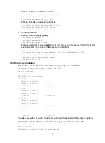
Страница 87: ...im6 c rp 1001 1 RouterA pim6 quit 4 Configure Router B Enable IPv6 multicast routing globally RouterB system view RouterB ipv6 multicast routing RouterB mrib6 quit Enable IPv6 PIM SM on each interface RouterB interface gigabitethernet 1 0 1 RouterB GigabitEthernet1 0 1 ipv6 pim sm RouterB GigabitEthernet1 0 1 quit RouterB interface gigabitethernet 1 0 2 RouterB GigabitEthernet1 0 2 ipv6 pim sm Rou...

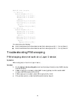
Страница 88: ...00 assign GigabitEthernet 1 0 1 through GigabitEthernet 1 0 4 to this VLAN and enable MLD snooping and IPv6 PIM snooping for the VLAN SwitchA vlan 100 SwitchA vlan100 port gigabitethernet 1 0 1 to gigabitethernet 1 0 4 SwitchA vlan100 mld snooping enable SwitchA vlan100 ipv6 pim snooping enable SwitchA vlan100 quit Verifying the configuration On Switch A display information about IPv6 PIM snooping...

Страница 89: ... FSM J The output shows the following Switch A will forward the multicast data intended for IPv6 multicast group FF1E 101 to only Router C Switch A will forward the multicast data intended for IPv6 multicast group FF2E 101 to only Router D Troubleshooting IPv6 PIM snooping This section describes common IPv6 PIM snooping problems and how to troubleshoot them IPv6 PIM snooping does not work on a Lay...

Страница 90: ... B Switch A sends one copy of the IPv6 multicast data to the IPv6 multicast VLAN on Switch B This saves network bandwidth and lessens the burden on the Layer 3 device IPv6 multicast VLANs include sub VLAN based IPv6 multicast VLANs and port based IPv6 multicast VLANs Sub VLAN based IPv6 multicast VLAN As shown in Figure 30 Host A Host B and Host C are in VLAN 2 through VLAN 4 respectively On Switc...

Страница 91: ...assigned to VLAN 10 MLD snooping is enabled for the IPv6 multicast VLAN and VLAN 2 through VLAN 4 Figure 31 Port based IPv6 multicast VLAN MLD snooping manages the router ports and member ports in the IPv6 multicast VLAN When Switch B receives an MLD message from a user port it tags the message with the IPv6 multicast VLAN ID and sends it to the MLD querier When Switch A receives IPv6 multicast da...

Страница 92: ...ed IPv6 multicast VLAN complete the following tasks Create VLANs as required Enable MLD snooping for the VLAN to be configured as the IPv6 multicast VLAN and for the VLANs to be configured as sub VLANs Configuration guidelines When you configure a sub VLAN based IPv6 multicast VLAN follow these guidelines The VLAN to be configured as the IPv6 multicast VLAN must exist A VLAN to be configured as a ...

Страница 93: ...N A 3 Configure the link type of the user port as hybrid port link type hybrid The default setting is access For more information about this command see Layer 2 LAN Switching Command Reference 4 Specify the PVID of the current user port as the VLAN to which the user port belongs port hybrid pvid vlan vlan id By default the PVID for a hybrid port is VLAN 1 For more information about this command se...

Страница 94: ...er port does not belong to any IPv6 multicast VLAN Setting the maximum number of IPv6 multicast VLAN forwarding entries You can set the maximum number of IPv6 multicast VLAN forwarding entries on the switch When the upper limit is reached the switch does not create IPv6 multicast VLAN forwarding entries until some entries age out or are manually removed If the total number of entries exceeds the u...

Страница 95: ...efix length vlan vlan id IPv6 multicast VLAN configuration examples Sub VLAN based IPv6 multicast VLAN configuration example Network requirements As shown in Figure 32 MLDv1 runs on Layer 3 device Switch A and MLDv1 snooping runs on Layer 2 device Switch B Switch A acts as the MLD querier The IPv6 multicast source sends IPv6 multicast data to IPv6 multicast group FF1E 101 Host A Host B and Host C ...

Страница 96: ...pe hybrid SwitchA GigabitEthernet1 0 1 port hybrid vlan 10 tagged SwitchA GigabitEthernet1 0 1 quit Assign an IPv6 address to VLAN interface 10 and enable MLD on this interface SwitchA interface vlan interface 10 SwitchA Vlan interface10 ipv6 address 2001 1 64 SwitchA Vlan interface10 mld enable SwitchA Vlan interface10 quit 2 Configure Switch B Enable MLD snooping globally SwitchB system view Swi...

Страница 97: ... 4 SwitchB ipv6 mvlan 10 quit Verifying the configuration Display information about all IPv6 multicast VLANs on Switch B SwitchB display ipv6 multicast vlan Total 1 IPv6 multicast VLANs IPv6 multicast VLAN 10 Sub VLAN list 3 in total 2 4 Port list 0 in total Display information about IPv6 multicast groups in IPv6 multicast VLANs on Switch B SwitchB display ipv6 multicast vlan group Total 1 entries...

Страница 98: ...uting globally SwitchA system view SwitchA ipv6 multicast routing SwitchA mrib6 quit Create VLAN 20 and assign GigabitEthernet 1 0 2 to this VLAN SwitchA vlan 20 SwitchA vlan20 port gigabitethernet 1 0 2 SwitchA vlan20 quit Assign an IPv6 address to VLAN interface 20 and enable IPv6 PIM DM on this interface SwitchA interface vlan interface 20 SwitchA Vlan interface20 ipv6 address 1 2 64 SwitchA Vl...

Страница 99: ...gigabitethernet 1 0 2 SwitchB GigabitEthernet1 0 2 port link type hybrid SwitchB GigabitEthernet1 0 2 port hybrid pvid vlan 2 Assign GigabitEthernet 1 0 2 to VLAN 2 and VLAN 10 as an untagged VLAN member SwitchB GigabitEthernet1 0 2 port hybrid vlan 2 untagged SwitchB GigabitEthernet1 0 2 port hybrid vlan 10 untagged SwitchB GigabitEthernet1 0 2 quit Configure GigabitEthernet 1 0 3 as a hybrid por...

Страница 100: ...B GigabitEthernet1 0 4 ipv6 port multicast vlan 10 SwitchB GigabitEthernet1 0 4 quit Verifying the configuration Display information about IPv6 multicast VLANs on Switch B SwitchB display ipv6 multicast vlan Total 1 IPv6 multicast VLANs IPv6 multicast VLAN 10 Sub VLAN list 0 in total Port list 0 in total GE1 0 2 GE1 0 3 GE1 0 4 Display information about MLD snooping group entries for dynamic IPv6 ...

Страница 101: ...st one x y Asterisk marked square brackets enclose optional syntax choices separated by vertical bars from which you select one choice multiple choices or none 1 n The argument or keyword and argument combination before the ampersand sign can be entered 1 to n times A line that starts with a pound sign is comments GUI conventions Convention Description Boldface Window names button names field name...

Страница 102: ... Represents an access controller a unified wired WLAN module or the access controller engine on a unified wired WLAN switch Represents an access point Represents a wireless terminator unit Represents a wireless terminator Represents a mesh access point Represents omnidirectional signals Represents directional signals Represents a security product such as a firewall UTM multiservice security gatewa...

Страница 103: ...s provide a mechanism for accessing software updates through the product interface Review your product documentation to identify the recommended software update method To download product updates go to either of the following Hewlett Packard Enterprise Support Center Get connected with updates page www hpe com support e updates Software Depot website www hpe com support softwaredepot To view and u...

Страница 104: ...r self repair CSR programs allow you to repair your product If a CSR part needs to be replaced it will be shipped directly to you so that you can install it at your convenience Some parts do not qualify for CSR Your Hewlett Packard Enterprise authorized service provider will determine whether a repair can be accomplished by CSR For more information about CSR contact your local service provider or ...

Страница 105: ...number edition and publication date located on the front cover of the document For online help content include the product name product version help edition and publication date located on the legal notices page ...

Страница 106: ...up policy 24 IP multicast IGMP snooping multicast group policy global 25 IP multicast IGMP snooping multicast group policy on port 25 IP multicast IGMP snooping multicast source port filtering 25 IP multicast IGMP snooping policy 24 IP multicast IGMP snooping port feature 18 IP multicast IGMP snooping querier 21 33 IP multicast IGMP snooping static port 19 30 IP multicast PIM snooping 38 39 IPv6 m...

Страница 107: ... IGMP snooping fast leave processing global 20 IP multicast IGMP snooping fast leave processing on port 20 IP multicast IGMP snooping report suppression 26 IP multicast MLD snooping fast leave processing global 62 IP multicast MLD snooping fast leave processing on port 62 IPv6 multicast MLD snooping 58 IPv6 multicast MLD snooping MLD snooping view 58 IPv6 multicast MLD snooping VLAN view 58 IPv6 m...

Страница 108: ...n 24 port feature configuration 18 protocols and standards 15 querier configuration 21 33 querier enable 21 query response parameter configuration 22 related ports 12 report suppression 26 simulated member host configuration 19 static port configuration 19 30 troubleshooting 36 troubleshooting Layer 2 multicast forwarding 36 troubleshooting multicast group policy 36 version specification 17 IGMPv1...

Страница 109: ...n shortest path tree SPT 4 overview 1 packet forwarding 11 PIM snooping configuration 37 38 39 79 80 81 protocols and standards 8 SFM model 5 SSM model 5 transmission technique 2 transmission techniques 1 troubleshooting IGMP snooping 36 troubleshooting IGMP snooping Layer 2 multicast forwarding 36 troubleshooting IGMP snooping multicast group policy 36 troubleshooting IPv6 PIM snooping 84 trouble...

Страница 110: ...12 IPv6 multicast MLD snooping member port 54 membership report IP multicast IGMP snooping 14 IPv6 multicast MLD snooping 56 message IGMP snooping message 802 1p priority 24 IP multicast IGMP snooping leave 14 IPv6 multicast MLD snooping basic configuration 58 IPv6 multicast MLD snooping configuration 54 57 70 IPv6 multicast MLD snooping done 56 IPv6 multicast MLD snooping fast leave processing en...

Страница 111: ...v6 multicast port based VLAN user port assignment 88 IPv6 multicast port based VLAN user port attribute configuration 88 MLD snooping group policy simulated joining configuration VLAN 70 MLD snooping IPv6 multicast source port filtering 67 multicast VLAN max forwarding entries 47 port based multicast VLAN configuration 46 port based multicast VLAN user port assignment 46 port based multicast VLAN ...

Страница 112: ...ng router port 12 IP multicast IGMP snooping static port 19 IP multicast IGMP snooping static port configuration 30 IP multicast PIM snooping configuration 38 39 IP multicast port based IPv6 multicast VLAN 86 IPv6 multicast MLD snooping aging timer for dynamic port 55 IPv6 multicast MLD snooping basic configuration 58 IPv6 multicast MLD snooping configuration 54 57 70 IPv6 multicast MLD snooping f...

Страница 113: ...nfiguring IPv6 multicast MLD query response parameters for VLAN MLD snooping 64 configuring IPv6 multicast MLD snooping 57 70 configuring IPv6 multicast MLD snooping basic features 58 configuring IPv6 multicast MLD snooping group policy 66 configuring IPv6 multicast MLD snooping group policy global 66 configuring IPv6 multicast MLD snooping group policy port 67 configuring IPv6 multicast MLD snoop...

Страница 114: ...er global 18 setting IP multicast IGMP snooping dynamic port aging timer VLAN 18 setting IP multicast IGMP snooping max forwarding entries 17 setting IPv6 multicast MLD snooping dynamic port aging timers global 60 setting IPv6 multicast MLD snooping dynamic port aging timers VLAN 60 setting IPv6 multicast MLD snooping max forwarding entries 59 setting IPv6 multicast VLAN max forwarding entries 89 ...

Страница 115: ... IP multicast IGMP snooping max forwarding entries 17 IP multicast IGMP snooping multicast group policy 24 IP multicast IGMP snooping multicast source port filtering 25 IP multicast IGMP snooping policy configuration 24 IP multicast IGMP snooping port feature 18 IP multicast IGMP snooping querier configuration 33 IP multicast IGMP snooping static port 19 IP multicast IGMP snooping static port conf...

Страница 116: ...LD snooping version MLD snooping view 59 MLD snooping version VLAN view 59 SPT IP multicast notation 4 SSM IP multicast model 5 static IP multicast IGMP snooping static port 19 IP multicast IGMP snooping static port configuration 30 MLD snooping static port configuration 60 sub VLAN based IPv6 multicast VLAN configuration 87 90 implementation 85 sub VLAN based multicast VLAN configuration 45 48 48...

Страница 117: ...ing multicast group replacement 26 IP multicast IGMP snooping policy configuration 24 IP multicast IGMP snooping port feature 18 IP multicast IGMP snooping querier 21 IP multicast IGMP snooping static port 19 IP multicast MLD query response parameters MLD snooping 63 IP multicast MLD snooping enable 58 IPv6 multicast MLD query response parameter configuration for VLAN MLD snooping 64 IPv6 multicas...

Отзывы: