background image

Display assembly diagram

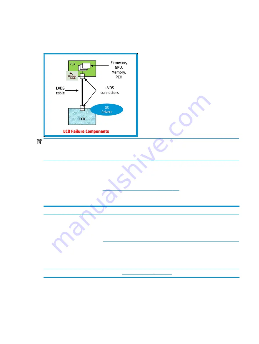
The display assembly diagram shows basic video components: system board, graphics cards, display cables, 
display connectors, operating system (OS), graphics driver, and LCD display panel. Any component or a 
combination of these components can contribute to a video issue.

NOTE:

The lid close switch is a Hall-effect sensor located in the top cover. When the display is closed, the 

sensor acts like a switch. A notebook can force a video output to an external monitor, or go to hibernation or 
standby mode through power management. If the display screen does not light up when the display is open, 
the lid close switch (Hall-effect sensor) could be faulty.

Dead pixel

Display panel may show one or more pixels that are not properly lit when displaying a single color over the 
screen area. Use HP PC Hardware Diagnostics (UEFI) tool to determine those defective pixels. There is no 
solution for dead pixels. Refer t

Display Issue: Pixel Anomalies on page 153

 for the HP dead pixel policy.

No video (internal)


Symptoms

No internal video with certain 
programs (i.e., video-intensive games)

Possible causes

Display resolution, brightness, faulty lid switch, running a program requiring a higher 
resolution than the display screen can support..

Faulty lid switch may put the system into Sleep or Hibernation mode.

Troubleshooting steps

Use an external monitor with higher resolution.

Test with external monitor using HDMI or HP port. Press the power button and close the 
computer lid to force video output to external video. If there is still no video, contact support.

References

See section 

No video (with power) on page 107

 for display information.

Common issues and possible solutions 121

Содержание ZBook 15u G4

Страница 1: ...HP EliteBook 850 G4 Notebook PC HP ZBook 15u G4 Mobile Workstation Maintenance and Service Guide ...

Страница 2: ...ribes features that are common to most models Some features may not be available on your computer Not all features are available in all editions of Windows This computer may require upgraded and or separately purchased hardware drivers and or software to take full advantage of Windows functionality Go to http www microsoft com for details Your product does not support Windows 8 or Windows 7 In acc...

Страница 3: ...hat should only be accessed by an authorized service provider See Chapter 5 Removal and replacement procedures for Customer Self Repair parts for details Accessing parts described in Chapter 6 Removal and replacement procedures for Authorized Service Provider only parts can damage the computer or void your warranty iii ...

Страница 4: ...iv Important Notice about Customer Self Repair Parts ...

Страница 5: ...w another hard surface such as an adjoining optional printer or a soft surface such as pillows or rugs or clothing to block airflow Also do not allow the AC adapter to contact the skin or a soft surface such as pillows or rugs or clothing during operation The device and the AC adapter comply with the user accessible surface temperature limits defined by the International Standard for Safety of Inf...

Страница 6: ...vi Safety warning notice ...

Страница 7: ... 18 Computer major components 18 Display assembly subcomponents 22 Plastics Kit 24 Mass storage devices 25 Cable Kit 26 Miscellaneous parts 27 4 Removal and replacement procedures preliminary requirements 29 Tools required 29 Service considerations 29 Plastic parts 29 Cables and connectors 30 Drive handling 30 Grounding guidelines 31 Electrostatic discharge damage 31 Packaging and transporting gui...

Страница 8: ...fan assembly 55 Fingerprint reader assembly 58 Touchpad board 59 NFC module 61 Smart card reader board 62 USB audio board 64 System board 65 Speaker assembly 69 Display assembly 70 Power button board 77 Top cover 79 7 Interpreting system validation diagnostic front panel LEDs and audible codes 80 8 Troubleshooting guide 82 Resources 83 General troubleshooting steps 83 Identify the issue 84 1 Under...

Страница 9: ...eshooting lights 94 Resolve the issue 95 8 Hard reset 95 9 Soft reset Default Settings 96 10 Reseat cables and connections 96 11 Test with minimum configuration 97 Essential hardware configuration 97 Safe mode 98 12 Test with verified working configuration hardware and or operating system 98 13 Replace the system board 98 Verify solution 99 Helpful Hints 99 At startup 99 During operation 100 Consu...

Страница 10: ...est 120 Display assembly diagram 121 Dead pixel 121 No video internal 121 No video external 122 DisplayPort VGA 122 HDMI 122 No or bad external video via docking 123 Incorrect or missing color distorted image 123 Touch screen 124 I O devices 125 Keyboard 125 Keyboard point stick 126 Keyboard backlight 126 TouchPad 127 Network Connectivity Ethernet RJ 45 jack 127 Network connectivity wireless WLAN ...

Страница 11: ...id BIOS Boot Block image 144 Sure Start has identified a problem Manual Recovery Policy Set 145 POST Error Messages and User Actions 145 Routine Maintenance for Performance Improvement 147 Common Blue Screen Error Messages 147 Error message list 147 Bug check symbolic names 147 Microsoft general troubleshooting of Windows bug check codes 148 Use Windows Debugging Tool 148 Windows Software Developm...

Страница 12: ...know before you get started 165 Using the HP Recovery partition select products only 166 Using HP Recovery media to recover 166 Changing the computer boot order 167 Removing the HP Recovery partition select products only 168 12 Specifications 169 Computer specifications 169 39 6 cm 15 6 in display specifications 170 Solid state drive specifications 170 Hard drive specifications 171 13 Power cord s...

Страница 13: ...Slim Docking Station DisplayPort and VGA ports sold separately Microsoft DirectX 12 Shader Model 5 0 and OpenGL 4 3 capable AMD Enduro Technology supported Panel 39 6 cm 15 6 in eDP slim display High definition HD AntiGlare AG SVA 220 nits 1366 x 768 with and without webcam Full high definition FHD AntiGlare AG SVA 300 nits 1920 x 1080 with and without webcam Ultra high definition UHD AntiGlare AG...

Страница 14: ...the following configurations 32768 MB 16384 MB 2 16384 MB 16384 MB 1 or 8192 MB 2 8192 MB 8192 MB 1 or 4096 MB 2 4096 MB 4096 MB 1 Primary storage Hard drives Supports 6 35 cm 2 5 in hard drives in 7 0 mm 28 in thicknesses Serial ATA 1 TB 5400 rpm 500 GB 7200 rpm self encrypting FIPS 140 2 500 GB 7200 rpm self encrypting Opal 2 500 GB 7200 rpm 500 GB hybrid 8 GB cache M 2 solid state drives PCIe 2...

Страница 15: ...bo card WLAN Integrated wireless local area network WLAN options by way of wireless module Supports the following WLAN formats Intel Dual band wireless AC 8265 802 11AC 2x2 WiFi BT 4 2 Combo Adaptor vPro Intel Dual band wireless AC 8265 802 11AC 2x2 WiFi BT 4 2 Combo Adaptor non vPro Intel Dual band wireless AC 3168 802 11AC 1x1 WiFi BT 4 2 Combo Adapter non vPro Two WLAN antennas built into displ...

Страница 16: ... RJ 45 Docking connector Audio out headphone audio in microphone combo jack AC port USB 3 1 Gen 1 charging port USB 3 1 Gen 1 port Docking Ultraslim side Docking Station 2013 Ultraslim Docking Station Keyboard pointing devices Keyboard Dual point Dura keys backlit spill resistant with drain Dual point spill resistant with drain TouchPad Gestures enabled by default two finger scrolling two finger p...

Страница 17: ...ws 10 Home 64 Windows 10 Professional 64 FreeDOS 2 0 NeoKylin 64 bit Preinstalled Windows 10 Home 64 Windows 10 Professional 64 FreeDOS 2 0 Restore Media DR SR DVD Windows 10 NeoKylin Linux Restore Media OS DVD Windows 10 Professional 64 USB Restore Windows 10 Windows 10 drivers Certified Microsoft WHQL Red Hat Enterprise Linux RHEL Web only support Windows 10 Enterprise Windows 10 Enterprise 64 L...

Страница 18: ...Category Description EliteBook 850 ZBook 15u Hard drive Solid state drive Memory module WLAN module WWAN module Keyboard 6 Chapter 1 Product description ...

Страница 19: ...ess in on the card until it is firmly seated To remove a card Press in on the card and then remove it from the memory card reader 4 Audio out headphone Audio in microphone combo jack Connects optional powered stereo speakers headphones earbuds a headset or a television audio cable Also connects an optional headset microphone This jack does not support optional microphone only devices WARNING To re...

Страница 20: ...curity cable slot Attaches an optional security cable to the computer NOTE The security cable is designed to act as a deterrent but it may not prevent the computer from being mishandled or stolen 2 Vents 2 Enable airflow to cool internal components NOTE The computer fan starts up automatically to cool internal components and prevent overheating It is normal for the internal fan to cycle on and off...

Страница 21: ...ce and chat online using streaming video To use the webcam Type camera in the taskbar search box and then select Camera The antennas are not visible from the outside of the computer For optimal transmission keep the areas immediately around the antennas free from obstructions For wireless regulatory notices see the section of the Regulatory Safety and Environmental Notices that applies to your cou...

Страница 22: ...e pointer or activate items on the screen 5 Left TouchPad button Functions like the left button on an external mouse 6 Right pointing stick button Functions like the right button on an external mouse 7 Near Field Communications NFC tapping area select products only Allows you to touch an NFC compatible device to this area to wirelessly connect and communicate with the computer and transfer data ba...

Страница 23: ...e light Amber microphone sound is off Off microphone sound is on 3 Num lk light On Num lock is on 4 Wireless light On An integrated wireless device such as a wireless local area network WLAN device and or a Bluetooth device is on NOTE On some models the wireless light is amber when all wireless devices are off 5 Mute light Amber Computer sound is off Off Computer sound is on 6 Caps lock light On C...

Страница 24: ...own the power button results in the loss of unsaved information If the computer has stopped responding and shutdown procedures are ineffective press and hold the power button for at least 15 seconds to turn off the computer To learn more about your power settings see your power options Type power options in the taskbar search box and then select Power Options or Right click the Power meter icon an...

Страница 25: ...ction key the num lk key the esc key or other key See Using the hot keys on page 14 3 Windows key Opens the Start menu NOTE Pressing the Windows key again will close the Start menu 4 Function keys Executes frequently used system functions when pressed in combination with the fn key See Using the hot keys on page 14 5 num lk key Turns the embedded numeric keypad on and off when pressed in combinati...

Страница 26: ...tes the screen image from computer display to monitor display to simultaneous display on both the computer and the monitor Most external monitors receive video information on the computer using the external VGA video standard The fn f4 hot key can also alternate images among other devices that are receiving video information on the computer Decreases the screen brightness incrementally as long as ...

Страница 27: ... optional docking device 2 Vents 2 Enable airflow to cool internal components NOTE The computer fan starts up automatically to cool internal components and prevent overheating It is normal for the internal fan to cycle on and off during routine operation Bottom 15 ...

Страница 28: ...on Hibernation is a power saving state that uses the least amount of power 3 Battery light When AC power is connected White The battery charge is greater than 90 percent Amber The battery charge is from 0 to 90 percent Off The battery is not charging When AC power is disconnected battery not charging Blinking amber The battery has reached a low battery level When the battery has reached a critical...

Страница 29: ... information to identify your computer When contacting support you will probably be asked for the serial number and possibly for the product number or the model number Locate these numbers before you contact support Component 1 Model name select products only 2 Product number 3 Serial number 4 Warranty period Regulatory label s Provide s regulatory information about the computer Wireless certifica...

Страница 30: ...rted parts for your computer go to http partsurfer hp com select your country or region and then follow the on screen instructions NOTE Details about your computer including model serial number product key and length of warranty are on the service tag at the bottom of your computer See Labels on page 17 for details 18 Chapter 3 Illustrated parts catalog ...

Страница 31: ...56 xx1 With a backlight 821157 xx1 3 Top cover HP EliteBook 850 G4 Notebook PC models 821191 001 HP ZBook 15u G4 Mobile Workstation models 821155 001 4 Power button board 914750 001 5 TouchPad HP EliteBook 850 G4 Notebook PC models Without NFC antenna 836620 001 Including NFC antenna 837851 001 HP ZBook 15u G4 Mobile Workstation models Without NFC antenna 821153 001 Including NFC antenna 821154 00...

Страница 32: ...ics Intel i7 7600U processor 917506 xx1 Intel i7 7500U processor 917505 xx1 Intel i5 7300U processor 917500 xx1 Intel i5 7200U processor 917502 xx1 Intel i3 7100U processor HP EliteBook 850 G4 Notebook PC models only 917498 xx1 14 Solid state drive SSD HP EliteBook 850 G4 Notebook PC models 512 GB PCIe Gen3x4 NVMe TLC 917758 001 512 GB PCIe Gen3x4 NVMe self encrypting SED Opal 2 TLC 917760 001 512...

Страница 33: ...2 11AC 2x2 WiFi BT 4 2 Combo Adaptor non vPro 851594 001 Intel Dual band wireless AC 3168 802 11AC 1x1 WiFi BT 4 2 Combo Adapter non vPro 852511 001 18 WWAN module HP lt4120 LTE EVDO HSPA SnapdragonT X5 LTE Mobile Broadband Module 800870 001 Huawei HP It4132 LTE HSPA w GPS M 2 845710 001 Fibocom HP hs3210 WW HSPA w o GPS 860726 001 19 RTC battery 914384 001 20 Memory module DDR 2400 4 GB 862397 85...

Страница 34: ...eft hinge cover 2b Right hinge cover Hinge Kit includes left and right hinges 821187 001 3a Left hinge 3b Right hinge 4 Microphone module 920485 001 5 Webcam module includes microphone 800575 020 6 Display webcam cable HD FHD and UHD 914749 001 Cable Kit 7 WLAN antenna spared with display enclosure 22 Chapter 3 Illustrated parts catalog ...

Страница 35: ... 15u G4 Mobile Workstation models FHD SVA 819354 003 FHD UWVA 819355 004 UHD UWVA 819356 004 10 Display enclosure includes antennas HP EliteBook 850 G4 Notebook PC models HD FHD models 821180 001 UHD models 918428 001 HP ZBook 15u G4 Mobile Workstation models FHD models 839528 001 UHD models 821151 001 UHD panel bracket not illustrated 919796 001 Display assembly subcomponents 23 ...

Страница 36: ...m Component Spare part number Plastics kit 821175 001 1 Fingerprint reader blank 2 Fingerprint reader bracket 3 SD card blank 4 Solid state drive insert 5 RJ 45 door 6 Rubber feet 24 Chapter 3 Illustrated parts catalog ...

Страница 37: ...d 8 GB cache 732000 001 2 Hard drive hardware kit 821665 001 3 Solid state drive M 2 HP EliteBook 850 G4 Notebook PC models 512 GB PCIe Gen3x4 NVMe TLC 917758 001 512 GB PCIe Gen3x4 NVMe self encrypting SED Opal 2 TLC 917760 001 512 GB PCIe Gen3x4 NVMe MLC 917755 001 512 GB SATA 3 FIPS 140 2 TLC 917382 003 360 GB PCIe Gen3 4 NVMe SS TLC 919691 003 256 GB PCIe Gen3 4 NVMe TLC 917757 001 Mass storag...

Страница 38: ...ive MLC 915931 001 512 GB PCIe Turbo Drive self encrypting SED Opal 2 TLC 915932 001 512 GB SATA 3 FIPS TLC 920051 001 256 GB PCIe Turbo Drive MLC 915933 001 256 GB PCIe Turbo Drive TLC 915929 001 256 GB SATA 3 self encrypting SED Opal 2 TLC 915928 001 Cable Kit Item Description Spare part number Cable Kit 914749 001 1 Display webcam cable HD FHD and QHD 2 Card reader cable 26 Chapter 3 Illustrate...

Страница 39: ...001 45 W HP Smart AC Adapter for use in Argentina 741553 852 Power cord 3 pin black 1 83 m for use in HP EliteBook 850 G4 Notebook PC models Argentina 401300 001 Australia 213356 001 Brazil 438722 001 Denmark 213353 001 Europe Austria Belgium Finland France Germany the Netherlands Norway and Sweden 213350 001 India 404827 001 Israel 398063 001 Italy 213352 001 Japan 349756 001 North America 213349...

Страница 40: ...ls Argentina 401300 010 Brazil 438722 007 Europe Austria Belgium Finland France Germany the Netherlands Norway and Sweden 213350 009 213350 012 India 404827 006 Israel 398063 006 Japan 349756 005 North America 213349 013 People s Republic of China 286497 011 South Africa 361240 005 South Korea 267836 011 Taiwan 393313 006 Thailand 285096 010 United Kingdom and Singapore 213351 011 Power cord 2 pin...

Страница 41: ...wing sections include some of the considerations that you must keep in mind during disassembly and assembly procedures NOTE As you remove each subassembly from the computer place the subassembly and all accompanying screws away from the work area to prevent damage Plastic parts CAUTION Using excessive force during disassembly and reassembly can damage plastic parts Use care when handling the plast...

Страница 42: ...ut down the computer If you are unsure whether the computer is off or in Hibernation turn the computer on and then shut it down through the operating system Before handling a drive be sure that you are discharged of static electricity While handling a drive avoid touching the connector Before removing a diskette drive or optical drive be sure that a diskette or disc is not in the drive and be sure...

Страница 43: ...ve these precautions Keep components in their electrostatic safe containers until you are ready to install them Before touching an electronic component discharge static electricity by using the guidelines described in this section Avoid touching pins leads and circuitry Handle electronic components as little as possible If you remove a component place it in an electrostatic safe container The foll...

Страница 44: ...er materials are selected to avoid static charging When grounding is not possible use an ionizer to dissipate electric charges Workstation guidelines Follow these grounding workstation guidelines Cover the workstation with approved static shielding material Use a wrist strap connected to a properly grounded work surface and use properly grounded tools and equipment Use conductive field service too...

Страница 45: ...m resistance between the operator and ground To be effective the conductive must be worn in contact with the skin The following grounding equipment is recommended to prevent electrostatic damage Antistatic tape Antistatic smocks aprons and sleeve protectors Conductive bins and other assembly or soldering aids Nonconductive foam Conductive tabletop workstations with ground cords of one megohm resis...

Страница 46: ...gion and then follow the on screen instructions There are as many as 26 screws that must be removed replaced and or loosened when servicing Customer Self Repair parts Make special note of each screw size and location during removal and replacement Bottom cover Description Spare part number Bottom cover for use in HP EliteBook 850 G4 Notebook PC models includes RJ 45 door feet sponge 821181 001 Bot...

Страница 47: ... using spare part number 821175 001 NOTE Multiple RJ 45 doors are available using spare part number 917396 001 The kit contains 20 doors 3 Remove the 11 Phillips M2 5x5 0 screws 1 11 and the Phillips M2 0x7 0 screw 12 in the order shown in the following image NOTE The longer Phillips M2 0x7 0 screw is located under the SD card reader Component replacement procedures 35 ...

Страница 48: ...e order indicated in the following image 1 12 IMPORTANT Failure to install the screws in the correct order can result in uneven bottom cover installation NOTE There are five different sizes of rubber screw covers Be sure that you reinstall them over the correct screws as shown in the following images The rubber screw cover sizes are shown in the following image 36 Chapter 5 Removal and replacement...

Страница 49: ...o orient the covers in the correct direction 1 Place the lower edge into the recess 1 followed by the higher edge 2 2 Use a small plastic rod or the soft part of your finger not a fingernail to ensure compaction into the recess 3 Visually inspect all rubber caps to be sure that they installed in the correct locations Run a finger over the tops of the rubber caps to ensure they are properly seated ...

Страница 50: ...e power cord from the AC outlet and then unplugging the AC adapter from the computer 4 Remove the bottom cover see Bottom cover on page 34 To remove the battery CAUTION Removing a battery that is the sole power source for the computer can cause loss of information To prevent loss of information save your work and shut down the computer through Windows before removing the battery Loosen the two cap...

Страница 51: ...hen shut it down through the operating system 2 Disconnect all external devices connected to the computer 3 Disconnect the power from the computer by first unplugging the power cord from the AC outlet and then unplugging the AC adapter from the computer 4 Remove the bottom cover see Bottom cover on page 34 5 Remove the battery see Battery on page 38 To remove a hard drive 1 Loosen the 4 captive sc...

Страница 52: ... remove the 4 Phillips M3 0 3 0 screws 1 that secure the cover to the drive and then lift the cover up and off the hard drive 2 Reverse this procedure to install a hard drive 40 Chapter 5 Removal and replacement procedures for Customer Self Repair parts ...

Страница 53: ...ED Opal 2 TLC 915932 001 512 GB SATA 3 FIPS TLC 920051 001 256 GB PCIe Turbo Drive MLC 915933 001 256 GB PCIe Turbo Drive TLC 915929 001 256 GB SATA 3 self encrypting SED Opal 2 TLC 915928 001 Before removing the solid state drive follow these steps 1 Turn off the computer If you are unsure whether the computer is off or in Hibernation turn the computer on and then shut it down through the operati...

Страница 54: ...y from the connector NOTE M 2 solid state drives are designed with notches to prevent incorrect insertion Reverse this procedure to install the solid state drive 42 Chapter 5 Removal and replacement procedures for Customer Self Repair parts ...

Страница 55: ...puter model 5 Select the operating system and then click Next 6 Under Step 2 Select a Download click the BIOS link 7 Click the link for the most recent BIOS 8 Click the Download button and then follow the on screen instructions Before removing the memory module follow these steps 1 Shut down the computer If you are unsure whether the computer is off or in Hibernation turn the computer on and then ...

Страница 56: ...the memory module slot NOTE The computer uses two memory sockets The socket labeled 2 houses the expansion memory module and the socket labeled 1 houses the primary memory module The removal procedure is the same for both memory sockets Reverse this procedure to install a memory module 44 Chapter 5 Removal and replacement procedures for Customer Self Repair parts ...

Страница 57: ...external devices connected to the computer 3 Disconnect the power from the computer by first unplugging the power cord from the AC outlet and then unplugging the AC adapter from the computer 4 Remove the bottom cover see Bottom cover on page 34 5 Remove the battery see Battery on page 38 Remove the WLAN module 1 Disconnect the WLAN antenna cables 1 from the terminals on the WLAN module NOTE The WL...

Страница 58: ... incorrect insertion NOTE If the WLAN antennas are not connected to the terminals on the WLAN module the protective sleeves must be installed on the antenna connectors as shown in the following illustration Reverse this procedure to install the WLAN module 46 Chapter 5 Removal and replacement procedures for Customer Self Repair parts ...

Страница 59: ... devices connected to the computer 3 Disconnect the power from the computer by first unplugging the power cord from the AC outlet and then unplugging the AC adapter from the computer 4 Remove the bottom cover see Bottom cover on page 34 5 Remove the battery see Battery on page 38 Remove the WWAN module 1 Position the computer upside down 2 Disconnect the WWAN antenna cables 1 from the terminals on...

Страница 60: ... incorrect insertion NOTE If the WWAN antennas are not connected to the terminals on the WWAN module the protective sleeves must be installed on the antenna connectors as shown in the following illustration Reverse this procedure to install the WWAN module 48 Chapter 5 Removal and replacement procedures for Customer Self Repair parts ...

Страница 61: ...o the computer 3 Disconnect the power from the computer by first unplugging the power cord from the AC outlet and then unplugging the AC adapter from the computer 4 Remove the bottom cover see Bottom cover on page 34 5 Remove the battery see Battery on page 38 Remove the RTC battery 1 Disconnect the battery cable from the system board 1 2 Lift the Mylar from atop the battery 2 3 Using a flat tool ...

Страница 62: ... 291 Sweden and Finland B71 Czech Republic and Slovakia FL1 Latin America 161 Switzerland BG1 Denmark 081 The Netherlands B31 Taiwan AB1 Denmark Finland and Norway DH1 Northern Africa FP1 Thailand 281 France 051 Norway 091 Turkey 141 Germany 041 Portugal 131 Turkey F 541 Greece 151 Romania 271 United Kingdom 031 Hungary 211 Russia 251 United States 001 Iceland DD1 Saudi Arabia 171 Before removing ...

Страница 63: ...les connect the bottom of the keyboard to the system board Make sure not to prematurely pull the keyboard cables out of the system board connectors 5 Position the computer upright with the front toward you and then open the computer as far as possible 6 Slide the keyboard slightly downward and then lift and rotate the keyboard over onto the palm rest 1 7 Lift the ZIF connector 2 for the pointing s...

Страница 64: ...10 Remove the keyboard 8 Reverse this procedure to install the keyboard 52 Chapter 5 Removal and replacement procedures for Customer Self Repair parts ...

Страница 65: ...elect your country or region and then follow the on screen instructions There are as many as 45 screws that must be removed replaced and or loosened when servicing Authorized Service Provider only parts Make special note of each screw size and location during removal and replacement Internal base plate Description Spare part number Internal base plate 821186 001 Before removing the internal base p...

Страница 66: ...internal base plate to the computer 2 Remove the 5 broadhead Phillips M2 5x2 5 screws that secure the internal base plate to the computer 3 3 Remove the base plate from the computer 4 Reverse this procedure to install the internal base plate 54 Chapter 6 Removal and replacement procedures for Authorized Service Provider parts ...

Страница 67: ...ter by unplugging the power cord from the computer 3 Disconnect all external devices from the computer 4 Remove the bottom cover see Bottom cover on page 34 5 Remove the battery see Battery on page 38 6 Remove the keyboard see Keyboard on page 50 7 Remove the internal base plate see Internal base plate on page 53 Remove the heat sink fan assembly 1 Discrete graphics models Loosen the eight captive...

Страница 68: ...UMA graphics models Loosen the six captive screws on the fan and heat sink following the sequence stamped on the fan and heat sink 1 disconnect the fan cable from the system board 2 and then remove the heat sink fan assembly from the system board 3 CAUTION Take extreme care when removing the heat sink and fan assembly The heatpipe is very fragile and can be easily damaged and bent during removal 5...

Страница 69: ...es of the heat sink and the system board components each time the heat sink is removed Replacement thermal material is included with the heat sink processor and system board spare part kits Reverse this procedure to install the heat sink fan assembly Component replacement procedures 57 ...

Страница 70: ... Bottom cover on page 34 5 Remove the battery see Battery on page 38 6 Remove the keyboard see Keyboard on page 50 7 Remove the internal base plate Internal base plate on page 53 Remove the fingerprint reader assembly 1 Position the computer upright and open all the way 2 Disconnect the fingerprint reader board cable from the system board 1 3 Close the computer and then position the computer upsid...

Страница 71: ...all external devices connected to the computer 3 Disconnect the power from the computer by first unplugging the power cord from the AC outlet and then unplugging the AC adapter from the computer 4 Remove the bottom cover see Bottom cover on page 34 5 Remove the battery see Battery on page 38 6 Remove the keyboard see Keyboard on page 50 7 Remove the internal base plate see Internal base plate on p...

Страница 72: ... the touchpad board up and then pull it forward to remove it from the computer 5 Reverse this procedure to install the touchpad board 60 Chapter 6 Removal and replacement procedures for Authorized Service Provider parts ...

Страница 73: ...y unplugging the power cord from the computer 3 Disconnect all external devices from the computer 4 Remove the bottom cover see Bottom cover on page 34 5 Remove the battery see Battery on page 38 6 Remove the keyboard see Keyboard on page 50 7 Remove the internal base plate see Internal base plate on page 53 Remove the NFC module 1 Disconnect the system board cable 1 and the NFC antenna 2 from the...

Страница 74: ...ng the power cord from the AC outlet and then unplugging the AC adapter from the computer 4 Remove the bottom cover see Bottom cover on page 34 5 Remove the battery see Battery on page 38 6 Remove the keyboard see Keyboard on page 50 7 Remove the internal base plate see Internal base plate on page 53 Remove the smart card reader board NOTE Before you remove the smart card reader make sure nothing ...

Страница 75: ...he board 3 use a thin tool to pry up the side of board near touchpad 4 and then pull the board away from the side of the computer to remove it from the clips built into the computer 5 Reverse this procedure to install the card reader board Component replacement procedures 63 ...

Страница 76: ...unplugging the AC adapter from the computer 4 Remove the bottom cover see Bottom cover on page 34 5 Remove the battery see Battery on page 38 6 Remove the keyboard see Keyboard on page 50 7 Remove the internal base plate see Internal base plate on page 53 Remove the USB audio board 1 Disconnect the cable from the system board 1 2 Remove the 2 Phillips M2 5 5 0 screws 2 that secure the USB audio bo...

Страница 77: ...odels only 917498 xx1 Before removing the system board follow these steps 1 Shut down the computer If you are unsure whether the computer is off or in Hibernation turn the computer on and then shut it down through the operating system 2 Disconnect all external devices connected to the computer 3 Disconnect the power from the computer by first unplugging the power cord from the AC outlet and then u...

Страница 78: ...puter upright and open as far as possible 2 Disconnect the card reader cable 1 and the fingerprint reader cable 2 from the system board by lifting the ZIF connectors and removing the cables from the connectors 3 Close the computer and position it upside down 66 Chapter 6 Removal and replacement procedures for Authorized Service Provider parts ...

Страница 79: ...Speaker cable 3 Display cable 4 Touch cable if equipped 5 Power button board cable 6 USB audio board cable 5 Remove the 2 Phillips M2 5 5 0 screws 1 that secure the system board to the computer 6 Lift the right side of the system board up at an angle 2 Component replacement procedures 67 ...

Страница 80: ...ght to disengage the connectors from the left side of the computer and then remove the system board 3 Reverse this procedure to install the system board 68 Chapter 6 Removal and replacement procedures for Authorized Service Provider parts ...

Страница 81: ...computer 4 Remove the bottom cover see Bottom cover on page 34 5 Remove the battery see Battery on page 38 6 Remove the keyboard see Keyboard on page 50 7 Remove the internal base plate see Internal base plate on page 53 8 Remove the system board see System board on page 65 Remove the speaker assembly 1 If necessary remove the antennas from the clip in the speaker assembly 2 Use a thin tool to pry...

Страница 82: ... off or in Hibernation turn the computer on and then shut it down through the operating system 2 Disconnect all external devices connected to the computer 3 Disconnect the power from the computer by first unplugging the power cord from the AC outlet and then unplugging the AC adapter from the computer 4 Remove the bottom cover see Bottom cover on page 34 5 Remove the battery see Battery on page 38...

Страница 83: ... s wireless performance 4 If you need to remove the display bezel flex the top 1 of the bezel the inside edges of the left and right sides 2 and then the bottom 3 of the bezel until it disengages from the display enclosure NOTE Make sure the hinges are not bent see hinge position in following image when you remove the bezel 5 Remove the display bezel 4 The display bezel is available using spare pa...

Страница 84: ...double sided tape on the display enclosure 1 and then disconnect the cable from the module 2 The webcam module is available using spare part number 800575 020 The microphone module is available using spare part number 920485 001 72 Chapter 6 Removal and replacement procedures for Authorized Service Provider parts ...

Страница 85: ...ok 850 G4 Notebook PC models HD panels 806864 005 FHD panels 721363 016 UHD panels 813033 002 HP ZBook 15u G4 Mobile Workstation models FHD SVA panels 819354 003 FHD UWVA panels 819355 004 UHD panels 819356 004 8 Rotate the display panel over onto the keyboard 1 9 On the back of the display panel lift the tape from atop the connector and then disconnect the display cable from the rear of the panel...

Страница 86: ...play enclosure and then remove the hinge covers 2 12 Remove the 6 Phillips M2 0x2 0 screws that secure the hinges to the display enclosure 3 and then remove the display hinges from the display enclosure 4 Display hinge covers and hinges are available in the Hinge Kit using spare part number 821187 001 74 Chapter 6 Removal and replacement procedures for Authorized Service Provider parts ...

Страница 87: ... is available in the Cable Kit using spare part number 914749 001 14 If it is necessary to replace the WLAN antenna cables peel the transceivers from the top of the display enclosure 1 remove the antenna cables from the routing path on the sides of the display enclosure 2 and then remove the antenna cables 3 NOTE The WLAN antennas are spared with the display enclosure Component replacement procedu...

Страница 88: ... enclosure The display enclosure is available using the following spare part numbers HP EliteBook 850 G4 Notebook PC models HD FHD models 821180 001 UHD models 918428 001 HP ZBook 15u G4 Mobile Workstation models FHD models 839528 001 UHD models 821151 001 The UHD panel bracket is available using spare part number 919796 001 Reverse this procedure to reassemble and install the display assembly 76 ...

Страница 89: ... to the computer 3 Disconnect the power from the computer by first unplugging the power cord from the AC outlet and then unplugging the AC adapter from the computer 4 Remove the bottom cover see Bottom cover on page 34 5 Remove the battery see Battery on page 38 6 Remove the internal base plate see Internal base plate on page 53 7 Remove the fan heatsink assembly see Heat sink fan assembly on page...

Страница 90: ...n the left side of the board and then remove the board from the computer 5 Reverse this procedure to install the power button board 78 Chapter 6 Removal and replacement procedures for Authorized Service Provider parts ...

Страница 91: ...r for use on HP EliteBook 850 G4 Notebook PC models 821191 001 Top cover for use on HP ZBook 15u G4 Mobile Workstation models 821155 001 The top cover remains after removing all other spared parts from the computer Component replacement procedures 79 ...

Страница 92: ...part code Major the category of the error Minor the specific error within the category NOTE Single beep blink codes are not used Number of long beeps blinks Error category 1 Not used 2 BIOS 3 Hardware 4 Thermal 5 System board Patterns of blink beep codes are determined by using the following parameters 1 second pause occurs after the last major blink 2 second pause occurs after the last minor blin...

Страница 93: ...ntroller is recovering the boot block or DXE Since it takes 10 sec or so to load the DXE image and get video in the DXE case this blink code is necessary SureStart Battery LED White and Amber blinking 2 4 Power LED red white Wait for DXE recovery to complete Hardware 3 2 The embedded controller has timed out waiting for BIOS to return from memory initialization CAP NUM Blink 3 3 2 Power LED red wh...

Страница 94: ...ks always disconnect power and remove the battery CAUTION Static electricity can damage the electronic components of the computer To prevent damage to the computer carefully observe the electrostatic discharge precautions Discharge static electricity by briefly touching a grounded metal object before you begin Work on a static free mat Wear a static strap to ensure that any accumulated electrostat...

Страница 95: ...troubleshooting steps A basic logic should be used when troubleshooting computer issues This section will help you become familiar with troubleshooting methodology and efficiently resolve problems Proceed through the steps in the following table until the issue is resolved and then move on to the next step that is relevant to the issue For example if you resolve a memory issue using the HP PC Diag...

Страница 96: ... hard drive memory etc are functional When POST is complete the HP logo displays briefly and then disappears If there are errors the computer may exhibit blinking lights and POST error messages Common issues lights blink error message appears hangs Performance operating system System boots to operating system and Windows logo screen appears Common issues hangs lock up freezes blue screen video dis...

Страница 97: ...nents stuck buttons thermal shutdown and so on NOTE Uncategorized is used if an issue found is not listed For example Bluetooth is offered on certain hardware configurations therefore a Bluetooth issue can be classified under I O Device if needed Failure classification by boot up sequence Table 8 3 Failure classification by boot up sequence 1 Power on 2 POST 3 Performance 1 No Power on page 101 2 ...

Страница 98: ... page 136 4 Slow performance on page 117c 5 Blue screen BSOD error on page 136b 6 Noisy hard drive on page 137 1 Fan error message 90B on page 138 2 Noise sound on page 139 3 Fan runs constantly on page 140 4 HP Thermal Monitor on page 91 5 Stuck power button on page 141 b c d similar symptoms 2 Examine the environment It is important to examine the computer s environment If you can quickly identi...

Страница 99: ...sers and IT personnel can use two tools to identify and download all appropriate SoftPaqs for the selected HP models HP SoftPaq Download Manager SDM is a software tool designed to streamline the download extraction and installation process of SoftPaqs including BIOS and drivers HP System Software Manager SSM is a software tool designed to simplify the deployment of SoftPaqs to HP computers Analyze...

Страница 100: ...e operating system so that it can isolate hardware failures from issues that are caused by the operating system or other software components In reality many problems can be determined using this tool if the issue is a defective part or a loose connection i e reseating keyboard cable after the tool reports a keyboard error The tool has three major functions System Tests Check the computer s hardwar...

Страница 101: ...e may vary NOTE Users should utilize this tool especially when the computer cannot boot to Windows NOTE If a component fails a test write down the information so it is available when contacting support The information is also available in Test Logs on the Main Menu For more information see the chapter titled Using HP PC Hardware Diagnostics UEFI General troubleshooting steps 89 ...

Страница 102: ...or Windows 10 HP is continually improving this tool Please verify the latest version is installed to receive the most benefit For more information see HP Support Assistant NOTE HPSA can be used only if the computer boots into Windows If the computer does not boot into Windows use HP PC Hardware Diagnostics UEFI instead HPSA also integrates diagnostics and tools that help resolve issues See example...

Страница 103: ...lutions to problems you encounter HP Thermal Monitor NOTE Available only to authorized service providers technicians Available only for HP internal use HP Thermal Monitor can be used to stress the processor and GPU and monitor the temperature values of various components in the system The components that are currently monitored include the processor GPU ACPI thermal zones hard drive and battery Th...

Страница 104: ... unsaved information If the computer has stopped responding and operating system shutdown procedures are ineffective press and hold the power button Front power light On The computer is on Blinking The computer is in the Sleep state Off The computer is off Front AC adapter and battery light White The computer is connected to external power and the battery is charged from 90 to 99 percent Amber The...

Страница 105: ...he Power On Self Test POST is a series of diagnostic tests that runs automatically when the computer is powered on If the POST encounters a problem visual error messages are displayed before the operating system starts POST checks the following items to ensure that the computer system is functioning properly Memory Processors BIOS Mass storage devices Fans The following table describes errors enco...

Страница 106: ...lacement chapter for further details Contact support if third party wireless adapters are installed in the computer Fan Fan not operating correctly 90B The system fan may be malfunctioning Replace the fan Power Good Troubleshooting lights HP has added troubleshooting power lights to ZBook G3 Mobile Workstations Studio ZBook 15 and ZBook 17 to help troubleshoot power on issues The lights indicate w...

Страница 107: ...ve Display suddenly goes blank and stays blank Software freezes Keyboard stops responding The computer does not exit Sleep or Suspend state An external device stops responding Turn off the power to that device in addition to performing the steps in this document Before performing a hard reset you must disconnect or remove all peripheral devices You should start and test the computer by itself and ...

Страница 108: ...ing action If your computer is having issues booting has errors during boot is running into issues after adding hardware or you are having other abnormal system behaviors that cannot be resolved through any other methods i e hard reset it may be necessary to reset the system BIOS to default settings To load BIOS to default settings Reboot the computer and then press F10 Main Restore defaults For m...

Страница 109: ...on to removing recently added components the issue can be narrowed down further with a minimum configuration For example if HP PC Diagnostics reports a memory error test one memory module at a time to isolate the defective module If the computer does not successfully boot the operating system booting to safe mode may help identify what may be causing the issue as described below Essential hardware...

Страница 110: ...esting A good example is to use an external keyboard mouse or VGA monitor when you have issues with an internal keyboard TouchPad or display Testing with a verified working AC adapter can identify an error caused by a faulty one Similarly testing with a verified working operating system can determine bad behaviors of the current operating system See Non HP diagnostics tools on page 91 for instruct...

Страница 111: ...it If the solution you used was in an HP Public document provide the document information to the customer letting them know it can be located on www hp com Also tell them that there are other solutions available on the website Advise the customer to check the website first when they have an issue It may save them time calling in Document the correct issue Update the case with as many details as po...

Страница 112: ...ot order 5 Be sure that all required device drivers have been installed For example if you have connected a printer you must install a printer driver 6 If there is a network connection issue plug another computer with a different cable into the network connection There might be a problem with the network plug or cable 7 If hardware has recently been installed remove it and determine whether the co...

Страница 113: ...er input to the computer external power source AC adapter faulty battery Bad connection to the computer bad power button power connector Defective parts memory hard drive graphics or failed system board Troubleshooting steps Perform quick check Remove all external devices including docking station Verify external power source 2 Examine the environment on page 86 Perform a hard reset 8 Hard reset o...

Страница 114: ...19 5 VDC and acceptable voltage range is from 18 5 20 5 VDC 2 If the DC voltage is out of range replace the AC adapter NOTE This action requires a digital voltmeter NOTE 2015 mWS does not have the power cable between system board and power connector on chassis Verify power button power connector 1 Be sure that power button is not stuck 2 Reseat power connector cable if applicable 3 Replace new pow...

Страница 115: ...sually check power ports on both AC adapter and computer sides 2 Inspect power sources a Verify AC adapter working correctly Use a confirmed working adapter to test b Verify that battery is not depleted while system is in Sleep state Test with a confirmed working battery The sections below are intended for authorized service providers technicians 1 Follow actions in No Power on page 101 a Be sure ...

Страница 116: ...Inspect AC adapter and power cord for physical damage bent middle ID pin 4 Plug in AC adapter and power the computer without battery 5 Inspect the power port on computer side for any damage dust debris 6 Check power light 7 Status lights blinking light codes troubleshooting lights and POST error messages on page 92 Rear power light indicates that external power to the computer is good 7 If there i...

Страница 117: ...attery is charging 4 Be sure that battery is fully charged AC adapter plugged in at least 2 5 hours Diagnostics HP tools will report results such as passed calibrate weak replace no battery and unknown and suggest corresponding actions Use HP Hardware Diagnostics UEFI 6 HP Hardware Diagnostics and Tools on page 88 HP PC Hardware Diagnostics UEFI is a good tool to use to isolate and determine fault...

Страница 118: ...2 Determine whether any graphics processing is running 3 Verify battery maintenance and operations Leaving the battery at a high level of charge in a high temperature environment for extended periods accelerates the loss of capacity 4 Test and calibrate battery using HP PC Hardware Diagnostics UEFI 5 Verify battery life cycle using HP Support Assistant tool If battery cycle life is over specs long...

Страница 119: ... with power Symptoms No video black blank image but have power Light activity No error messages Fan noise Hard drive light blinking and hard drive noise Possible causes Failed display Failed critical components memory hard drive system board Loose connection Recently added hardware NOTE Assume the computer has not previously been set up for multiple displays Troubleshooting steps Quick check 1 Ver...

Страница 120: ...sists test or replace a confirmed working display 10 If issue persists replace discrete graphics card 11 If issue persists replace system board due to defective video function Tips and tricks Swipe a metal piece screwdriver over wireless mute buttons to act as if closing lid to force video output to external display device See the External component identification Display section for location of t...

Страница 121: ... messages on page 92 for corrective actions An example of a POST error message is shown below 2 If there is power you may be able to access BIOS Reset BIOS to its default condition 9 Soft reset Default Settings on page 96 3 Restore hardware to its original condition i e bootable solid state drive instead of hard drive 4 Reseat suspected components and verify connection 5 Test suspected components ...

Страница 122: ...o to Manuals White papers HP PC BIOS F10 Setup Guide Performance OS NOTE Most software problems occur as a result of the following The application was not installed or configured correctly There is insufficient memory available to run the application There is a conflict between applications Make sure that all the needed device drivers are installed If an operating system other than the factory ope...

Страница 123: ...power options and close all applications that are not in use including applications in the background 2 Test with a confirmed working operating system to isolate custom settings by users or any conflicting applications that cause shutdown The sections below are intended for authorized service providers technicians Thermal related issue 1 Verify thermal condition a Test fan using HP PC Hardware Dia...

Страница 124: ...e malfunctioning due to overheating GPU processor Defective hardware memory hard drive Important Notes Resources Troubleshooting steps There are many different ways to troubleshoot a blue screen error Therefore you need to identify working configuration Windows 7 8 10 and specific symptoms of the failure in order to narrow down the issue Refer to Blue screen BSOD error on page 136 Recommended reso...

Страница 125: ... specific Error Message See Common Blue Screen Error Messages on page 147 e Boot to safe mode 11 Test with minimum configuration on page 97 to troubleshoot issues 9 If you cannot start Windows a Boot to safe mode 11 Test with minimum configuration on page 97 b Use Startup Repair to fix Windows startup files c Undo recent changes using System Restore to revert to a previous working state d Check fo...

Страница 126: ...tings to view error messages Freeze at Windows Logo hang lockup Symptoms Has power light activity fan spinning HP Logo displays briefly Attempt to boot to operating system and freeze hang at Windows logo No response to pressing num lock or caps lock key Possible causes Conflict of instructions from multiple programs or drivers installing a new hardware or program that is not compatible may also ca...

Страница 127: ...nfiguration on page 97 8 Use Startup Repair Windows to fix Windows damaged files 9 Test with essential hardware configuration 11 Test with minimum configuration on page 97 along with a verified working operating system i e USB Windows To Go if available to isolate the software issue Tips and tricks For more information see HP PCs Using Task Manager Windows 10 8 Electromagnetic Interference EMI Sym...

Страница 128: ...ent in Power Menu 4 Update BIOS and drivers on page 87 3 Verify power management settings in Windows Power Options Disable Sleep options if the issue is resolved 4 Screen saver is set Press any key or touch TouchPad to resume 5 Verify that Display Choice is set to external video only Toggle screen control key combination Fn F4 or Windows logo P Tips and tricks If you are using a docking station se...

Страница 129: ...omputer is not blocked 2 Verify that chassis fans are connected and working properly Some fans operate only when needed 3 Verify that the processor heat sink is installed properly Hard drive is full 1 Transfer data from the hard drive to create more space on the hard drive Microsoft recommends at least 200 MB to sync system files 2 Perform disk defragmentation to consolidate fragmented data on the...

Страница 130: ...ote HP Smart AC adapter warning message informs you that as power demands increase the notebook may not perform at full capacity which may result in longer battery charging time In cases of extreme power demands the system may also throttle back the processor or with systems that have a discrete video sub system a video balance mode may occur to further balance the power needs of the system System...

Страница 131: ...lack video Incorrect missing color distorted image Flickering image Vertical lines due to LDVS decreased signal integrity and data loss Dead pixel due to display liquid internal transistor etc Horizontal lines due to video memory Distorted when hot due to thermal issue Cracked screen image physical damage Light leakage bleeding Contact support for assistance Humming noise due to frequency settings...

Страница 132: ...system i e shipping image HP PC Hardware Diagnostics UEFI for video test Use this tool to quickly determine if the display issue is related to a real hardware issue To start HP PC Hardware Diagnostics UEFI 6 HP Hardware Diagnostics and Tools on page 88 when the computer is at boot press the F2 key select Component Tests and then select Video There are three options Video Memory Check to test video...

Страница 133: ...rly lit when displaying a single color over the screen area Use HP PC Hardware Diagnostics UEFI tool to determine those defective pixels There is no solution for dead pixels Refer to Display Issue Pixel Anomalies on page 153 for the HP dead pixel policy No video internal Symptoms No internal video with certain programs i e video intensive games Possible causes Display resolution brightness faulty ...

Страница 134: ...output to external video by closing the notebook lid or pressing Fn F4 to switch screen output DisplayPort VGA See No video external on page 122 HDMI Symptoms Display issue Sound issue Possible causes Cable connection settings Troubleshooting steps Quick Check 1 Verify HDMI device input source is set correctly i e HDMI1 2 Be sure you are using the correct HDMI cable 3 Check connection and reconnec...

Страница 135: ...system 8 Ideally use a verified working docking station to isolate the faulty dock 9 Update latest dock firmware Be sure to follow the installation instructions carefully You may want to try a DP to VGA adapter if you have a distorted screen image Connect the adapter to each DisplayPort of the dock If you still cannot update the dock attempt to update it on a confirmed working notebook before havi...

Страница 136: ...d graphics drivers 3 Configure the touch display to identify the screen as a touch screen as shown in the image at left 4 Calibrate the screen and reset if touch functionality is still not working correctly 5 Perform diagnostic test in HP Hardware Diagnostics under Component Tests Touch Screen If the diagnostics tests pass but the touch screen still does not respond continue following the steps 6 ...

Страница 137: ...s recognized in Windows Device Manager and verify whether the keyboard driver is installed properly 4 Test with a working external keyboard i e USB keyboard Also test in Windows for special keys Caps Lock Shift Ctrl Fn Windows Alt if necessary 5 Test with HP PC Hardware Diagnostics UEFI to isolate a hardware issue from a software issue 6 Verify that BIOS is up to date If so resetting BIOS to defau...

Страница 138: ...ectors on system board and back of keyboard and that connector tabs are properly closed 3 Reseat point stick cables Keyboard backlight Symptom Backlight function not working properly Possible causes Backlight disabled loose connection Troubleshooting steps NOTE Not all notebook computers have backlit keyboards A keyboard function key lets you turn the light on and off Verify if backlit feature is ...

Страница 139: ...Connectivity Ethernet RJ 45 jack Symptoms Unable to find networks yellow bang Connection dropouts Slow performance Possible causes Network source cable connection RJ 45 port driver settings Troubleshooting steps Quick Check verify the network status lights that supposed to flash when there is network activity HP Support Assistant tool No network detected in HPSA 1 Turn off the computer s wireless ...

Страница 140: ...oubleshooting steps 1 Turn off the computer s wired network remove RJ 45 cable 2 Examine environment for interference such as cell phone or microwave that may emit high frequencies above 1 GHz 3 Verify wireless source by moving computer closer to the wireless base router 4 Test with different wireless networks and check with your IT department for hardware compatibility settings 5 Verify that the ...

Страница 141: ...tion are not loose 3 Verify antenna cables are properly connected to the MAIN and AUX terminals see WLAN module removal and replacement section WWAN Symptom Unable to find networks service Possible causes Network source cable connection driver settings Troubleshooting steps 1 Update to the latest driver and utility 2 Check with network service provider for signal coverage 3 Make sure signal streng...

Страница 142: ... Device Manager Universal Serial Bus Controller or USB is recognized without Yellow bang 4 Verify if the latest USB driver or and USB chipset driver are installed USB driver could be removed and reinstalled 5 Make sure USB device is supported for example USB 3 0 device requires more power drawn 0 9A from USB port than USB 2 0 device 0 5A As a result identify USB charging port to be used for chargi...

Страница 143: ... material closing a hole or spoiling a metal contact Clean the contacts with a lint free cloth and small amounts of isopropyl alcohol Replace the memory card if necessary 4 Reinstall and update the drivers for the card reader 5 Make sure the smart card reader is compliant with ISO 7816 Class A B and C 6 Reinsert the card reader with correct face as described in its documentation 7 Check reader fun...

Страница 144: ...e full operating system 8 Test with verified working external speakers or headset 9 Reseat internal speaker connections 10 Test with verified working internal speakers 11 Replace internal speakers No sound from headphones 1 Adjust volume by pressing Fn F6 F7 Be sure that volume button light is not amber mute Or adjust Windows volume control by clicking the speaker icon on the Windows taskbar Be su...

Страница 145: ...n for TB controller driver version operating system driver and application version 4 Verify that TB device is detected in Windows Device Manager 5 Verify TB port cable and connection 6 Test with a verified working TB board if possible NOTE Thunderbolt is new technology Thunderbolt cable and Thunderbolt device must be compatible with Windows To determine whether your device is Thunderbolt Certified...

Страница 146: ...han 10 minutes identify the malfunctioning drive If the issue still exists run Extensive Test more than 2 hours or loop mode which will run until an error occurs If any test fails record failure code and contact support for instructions on how to order a replacement hard drive If all of the tests pass the hard drive is not damaged As a rule HP will not replace a hard drive under warranty that does...

Страница 147: ...ated issues No boot to operating system no read write error Symptoms Post error message Boot Device not found 3F0 Hang when booting to operating system Possible causes Operating system loose connection faulty hard drive BIOS configuration Secure Boot Troubleshooting steps 1 Verify if Secure Boot is enabled in BIOS Secure Boot prevents legacy boot devices from starting the computer including bootab...

Страница 148: ...ge 145 Slow performance Symptoms Slow performance even when performing small read write operations Possible causes Operating system files hard drive is full Troubleshooting steps 1 Transfer data from the hard drive to create more space Microsoft recommends at least 200 MB to sync system files 2 Perform disk defragmentation to consolidate fragmented data on the hard drive so it will work more effic...

Страница 149: ...rking computer if the noise continues If the hard drive makes the same noise or clicking sounds the sounds are either normal sounds for the hard drive or a fault with the hard drive 5 Verify original hard drive connection and flex cable Reseat hard drive and connection 6 Run HP PC Hardware Diagnostics UEFI If failed record failure code and have the hard drive replaced 7 If no error with HP PC Hard...

Страница 150: ... sure that no obstructions or dust are in heat sink fan fin or vent c Test fan using HP PC Hardware Diagnostics UEFI tool 6 HP Hardware Diagnostics and Tools on page 88 Be sure that the fan is not producing loud noise and that fan blades spin correctly d Test with a verified working fan e Remove old thermal compound and pads and replace properly with new pads 2 Verify thermal solution Use Thermal ...

Страница 151: ...noise originates from fan If noise is absent with fan disconnected refer to Fan runs constantly on page 140 Noisy hard drive Determine whether the noise comes from the hard drive See Noisy hard drive on page 137 Noisy optical drive 1 Determine whether the noise comes from an optical drive 2 Remove CD DVD from the optical drive Noisy speaker 1 Determine whether the noise comes from speaker 2 Test w...

Страница 152: ...e Diagnostics and Tools on page 88 Be sure that the fan is not producing loud noise and that fan blades spin correctly d Test with a verified working fan e Replace the fan 2 Verify thermal solution Use Thermal Monitor tool available only to authorized service providers technicians HP Thermal Monitor on page 91 to run stress test processor and GPU and verify that thermal sensors are within limits a...

Страница 153: ...est fan using HP PC Hardware Diagnostics UEFI tool 6 HP Hardware Diagnostics and Tools on page 88 Be sure that the fan is not producing a loud noise and that fan blades spin correctly e Test with a verified working fan f Remove old thermal compound and pads and replace properly with new pads 2 Verify thermal solution Use Thermal Monitor tool available only to authorized service providers technicia...

Страница 154: ... computer ran into a problem and needs to restart CPU Central processing unit DIMM Dual in line memory module Daughterboard Type of circuit board that plugs into or is attached to the system board or similar expansion card to extend its features and services GPU Graphics processor unit GTS General Troubleshooting Step HDD Hard drive KB Keyboard LVDS Low Voltage Differential Signaling MSG Maintenan...

Страница 155: ... If this error reoccurs refer to General troubleshooting steps on page 83 NOTE The computer will attempt to notify you of this problem through a series of blinking lights When you attempt to turn on the computer from an Off or Hibernated state lights associated with the caps lock and num lock keys will both blink once followed by a pause and then continue in a repeating pattern BIOS recovery code ...

Страница 156: ...n the computer from an Off or Hibernated state lights associated with the caps lock and num lock keys will both blink five times followed by a pause then continue in a repeating pattern Intel Trusted Execution Technology TXT Error This computer has experienced a problem related to the Intel Trusted Execution Technology resulting in a failed startup The error occurs when all of the following are tr...

Страница 157: ...k 1 SMART 301 Attempt to reseat the hard drive and repeat the test The hard disk drive may have failed Contact support for assistance Startup test Hard Disk 2 SMART 302 The hard drive may have failed Contact support for assistance Startup test Hard Disk 1 Quick 303 The hard drive may have failed Contact support for assistance Startup test Hard Disk 2 Quick 304 The hard drive may have failed Contac...

Страница 158: ...wnload the latest version of the BIOS and install it See 4 Update BIOS and drivers on page 87 for more information If reinstalling the BIOS fails contact support for further assistance CMOS Recovery CMOS Recovery Occurred 502 This message indicates that CMOS recovery was completed successfully No further action is required Battery Check Primary Battery Replace 601 This indicates that the primary b...

Страница 159: ...user files X Create a restore point X Defragment the hard drive X Run Scan Disk X Clean the exterior of the computer X Close programs that are not being used X Prevent programs from loading at startup X Common Blue Screen Error Messages Error message list The following image shows an example of one possible Bug Check Blue Screen Code Reference from Microsoft The hexadecimal number following the wo...

Страница 160: ...corruption can generate system bug check codes Be sure that the virus detection program checks the Master Boot Record for infections Verify that the system has the latest service pack installed To detect which service pack if any is installed on your system click Start click Run type winver and then press Enter The About Windows dialog box displays the Windows version number and the version number...

Страница 161: ... Kit SDK 1 Download the SDK from the following link https msdn microsoft com en us windows desktop bg162891 aspx 2 Set up the SDK in the configuration window Windows 10 shown 3 Select features to install Additional information 149 ...

Страница 162: ...an administrator 5 Set the symbol path Select File Symbol File Path In the Symbol path box type SRV C Windows symbol_cache http msdl microsoft com download symbols Save the workspace 150 Chapter 8 Troubleshooting guide ...

Страница 163: ...6 Open the crash dump file Additional information 151 ...

Страница 164: ...nalyze the file In the following memory dump sample look for Bug Check 0x3B The ATIKMAG driver needs to be investigated for further root cause Lookup for Bug Check 0xC2 152 Chapter 8 Troubleshooting guide ...

Страница 165: ...maged displays are submitted for warranty coverage Source HP Notebook PCs and Tablets About LCD Panel Defects and Terminology for Notebook PCs and Tablets Table 8 8 Electrical defect allowances Panel resolution Accept Reject Sub pixel faults VGA SVGA SD WSVGA XGA 720p SD WXGA HD N 2 Type 1 N 2 Type 2 N 3 Type 1 WXGA SXGA HD SXGA N 3 Type 1 N 3 Type 2 N 4 Type 1 WSXGA UXGA FHD WUXGA N 4 Type 1 N 4 ...

Страница 166: ...round the heat sink Do not jam cables on top of daughterboards or memory modules DIMMs Circuit cards and DIMMs are not designed to take excessive pressure Keep cables clear of any movable or rotating parts such as a fan to prevent them from being cut or crimped when the component is lowered into its normal position In all cases avoid bending or twisting the cables Do not bend any cable sharply A s...

Страница 167: ...he system board always follow these steps 1 Squeeze on the top of the retaining latch attached to the cable end of the connector 2 Grasp the cable end of the connector and pull it straight out CAUTION Always release connector latch before removing the cable Otherwise pulling the cable could damage the cable pins and result in a failed device Horizontal installation cable Use flat tool to pull conn...

Страница 168: ...onnector 1 Remove tape 2 Pull up bar pull tape and release the lock with the PCB connector 3 Pull to the direction in parallel with PCB to withdraw the connector Multi pin vertical insert connector LVDS cable to system board Remove the connector gasket prior to removing the connector Use flat tool under the connector to remove evenly Do not pull on the cable to remove Press evenly when reseating r...

Страница 169: ...oard arrow keys and then press enter or use a pointing device to select the item To scroll up and down select the up arrow or the down arrow in the upper right corner of the screen or use the up arrow key or the down arrow key on the keyboard To close open dialog boxes and return to the main Computer Setup screen press esc and then follow the on screen instructions To exit Computer Setup menus cho...

Страница 170: ...ble on the HP website Most BIOS updates on the HP website are packaged in compressed files called SoftPaqs Some download packages contain a file named Readme txt which contains information regarding installing and troubleshooting the file Determining the BIOS version To decide whether you need to update Computer Setup BIOS first determine the BIOS version on your computer BIOS version information ...

Страница 171: ...ter it has been downloaded to your hard drive b Follow the on screen instructions to download your selection to the hard drive Make a note of the path to the location on your hard drive where the BIOS update is downloaded You will need to access this path when you are ready to install the update NOTE If you connect your computer to a network consult the network administrator before installing any ...

Страница 172: ...ou change the TPM setting to Hidden TPM is not visible in the operating system To access TPM settings in Computer Setup 1 Start Computer Setup See Starting Computer Setup on page 157 2 Select Security select TPM Embedded Security and then follow the on screen instructions Using HP Sure Start select products only Select computer models are configured with HP Sure Start a technology that monitors th...

Страница 173: ...lowing order a Connected USB drive NOTE To download the HP PC Hardware Diagnostics UEFI tool to a USB drive see Downloading HP PC Hardware Diagnostics UEFI to a USB device on page 161 b Hard drive c BIOS 3 When the diagnostic tool opens select the type of diagnostic test you want to run and then follow the on screen instructions NOTE If you need to stop a diagnostic test press esc Downloading HP P...

Страница 174: ...des a BIOS crisis recovery tool through the HP PC Hardware Diagnostics 3 in 1 USB key This tool can be used by HP authorized service providers to recover systems that have failed due to a corrupted BIOS For more information about using the 3 in 1 USB key for BIOS crisis recovery go to http www hp com go techcenter pcdiags Additional information is included in the web based training offered by HP U...

Страница 175: ...covery partition on the computer The backup can be used to reinstall the original operating system in cases where the hard drive is corrupted or has been replaced For information on creating recovery media see Creating HP Recovery media select products only on page 163 For information on the recovery options that are available using the recovery media see Using Windows tools on page 164 Use Window...

Страница 176: ...ed separately to create recovery discs If you use an external optical drive it must be connected directly to a USB port on the computer the drive cannot be connected to a USB port on an external device such as a USB hub If you cannot create DVD media yourself you can obtain recovery discs for your computer from HP See the Worldwide Telephone Numbers booklet included with the computer You can also ...

Страница 177: ... remove the recovery partition to reclaim hard drive space HP Recovery Manager offers the Remove Recovery Partition option For more information see Removing the HP Recovery partition select products only on page 168 Recovering using HP Recovery Manager HP Recovery Manager software allows you to recover the computer to its original factory state by using the HP Recovery media that you either create...

Страница 178: ... discs or a recovery USB flash drive This type of recovery can be used only if the hard drive is still working To start HP Recovery Manager from the HP Recovery partition IMPORTANT For a tablet with a detachable keyboard connect the keyboard to the keyboard dock before beginning these steps select products only 1 Type recovery in the taskbar search box select Recovery Manager and then select HP Re...

Страница 179: ...e the boot order IMPORTANT For a tablet with a detachable keyboard connect the keyboard to the keyboard dock before beginning these steps 1 Insert the HP Recovery media 2 Access the system Startup menu For computers or tablets with keyboards attached Turn on or restart the computer or tablet quickly press esc and then press f9 for boot options For tablets without keyboards Turn on or restart the t...

Страница 180: ...HP Recovery partition So before you remove the Recovery partition create HP Recovery media see Creating HP Recovery media select products only on page 163 NOTE The Remove Recovery Partition option is only available on products that support this function Follow these steps to remove the HP Recovery partition 1 Type recovery in the taskbar search box and then select HP Recovery Manager 2 Select Remo...

Страница 181: ...35 C 32 F to 95 F Operating writing to optical disc 5 C to 35 C 41 F to 95 F Nonoperating 20 C to 60 C 4 F to 140 F Relative humidity Operating 10 to 90 Nonoperating 5 to 95 Maximum altitude unpressurized Operating 14 7 to 10 1 psia 15 m to 3 048 m 50 ft to 10 000 ft Nonoperating 14 7 to 4 4 psia 15 m to 12 192 m 50 ft to 40 000 ft Shock Operating 125 g 2 ms half sine Nonoperating 200 g 2 ms half ...

Страница 182: ...MB 1260 MB s 1550 MB s 1550 MB s Random read IOPS 4KB 300K 300K 210K Random write IOPS 4KB 100K 100K 130K Endurance Total bytes written 146 TB 292 TB 600 TB Interface PCI Express 2 0 x4 electrical x4 physical PCI Express 2 0 x4 electrical x4 physical PCI Express 2 0 x4 electrical x4 physical Form factor Half height half length Half height half length Half height half length Weight 51 g 51 g 51 g O...

Страница 183: ...cluding setting Single track 1 4 ms 3 ms 2 ms Average 10 ms 13 ms 12 ms Maximum 12 ms 24 ms 22 ms Logical blocks 1 938 921 461 1 048 576 000 976 773 168 Disc rotational speed 5400 rpm 7200 rpm or 5400 rpm 5400 rpm Operating temperature 1 GB 1 billion bytes when referring to hard drive storage capacity Actual accessible capacity is less Actual drive specifications may differ slightly NOTE Certain r...

Страница 184: ...t be approved by an acceptable accredited agency responsible for evaluation in the country or region where the power cord set will be used The power cord sets must have a minimum current capacity of 10 amps and a nominal voltage rating of 125 or 250 V AC as required by the power system of each country or region The appliance coupler must meet the mechanical configuration of an EN 60 320 IEC 320 St...

Страница 185: ...all plug must bear a T mark and registration number in accordance with the Japanese Dentori Law The flexible cord must be Type VCT or VCTF 3 conductor 1 00 mm conductor size The wall plug must be a two pole grounding type with a Japanese Industrial Standard C8303 7 A 125 V configuration 4 The flexible cord must be Type RVV 3 conductor 0 75 mm conductor size Power cord set fittings appliance couple...

Страница 186: ... below to restore the nonvolatile memory that can contain personal data Restoring or reprogramming nonvolatile memory that does not store personal data is neither necessary nor recommended a Turn on or restart the computer and then press esc while the Press the ESC key for Startup Menu message is displayed at the bottom of the screen IMPORTANT If the Main menu displays Restore Defaults instead of ...

Страница 187: ... retain the storage drive or Clear the drive contents by using a third party utility designed to erase data from an SSD or Clear the contents of the drive by using the following BIOS Setup Secure Erase command option steps IMPORTANT If you clear data using Secure Erase it cannot be recovered a Turn on or restart the computer and then press esc while the Press the ESC key for Startup Menu message i...

Страница 188: ...S Security to factory default Click Yes at the warning message g Select the Main menu select Save Changes and Exit select Yes to save changes and exit and then select Shutdown h Reboot the system If the system has a Trusted Platform Module TPM and or fingerprint reader one or two prompts will appear one to clear the TPM and the other to Reset Fingerprint Sensor press or tap F1 to accept or F2 to r...

Страница 189: ...t select models only on page 180 Data cannot be written to this device via the host processor The content is managed solely by the HP Sure Start Embedded Controller This memory is protected by the HP Sure Start Embedded Controller Real Time Clock RTC battery backed up CMOS configuration memory 256 Bytes No Yes Stores system date and time and noncritical data RTC battery backed up CMOS is programme...

Страница 190: ...ent Engine MEBx setup utility The third party data store contents can be populated by a remote management console or local applications that have been registered by an administrator to have access to the space The Intel chipset is configured to enforce hardware protection to block all direct read write access to this area An Intel utility is required for updating the firmware Only firmware updates...

Страница 191: ...S is an industry standard software interface between the platform firmware and an operating system OS It is a replacement for the older BIOS architecture but supports much of the legacy BIOS functionality Like the legacy BIOS the UEFI BIOS provides an interface to display the system information and configuration settings and to change the configuration of your computer before an OS is loaded BIOS ...

Страница 192: ...cure Boot Keys be reset Secure Boot is a feature to ensure that only authenticated code can start on a platform If you enabled Secure Boot and created Custom Secure Boot Keys simply disabling Secure Boot will not clear the keys You must also select to clear the Custom Secure Boot Keys Use the same Secure Boot access procedure you used to create the Custom Secure Boot Keys but make the selection to...

Страница 193: ...e battery in general household waste Follow the local laws and regulations in your area for battery disposal HP encourages customers to recycle used electronic hardware HP original print cartridges and rechargeable batteries For more information about recycling programs see the HP Web site at http www hp com recycle 181 ...

Страница 194: ...factory settings 157 computer specifications 169 connector power 8 D display assembly removal 70 spare part numbers 70 subcomponents 22 display bezel removal 71 display cable spare part number 22 display enclosure spare part number 23 display hinge removal 73 display image switching 14 display panel product description 1 display specifications 170 docking product description 4 docking connector id...

Страница 195: ...ule spare part number 22 microphone mute key identifying 14 microphone mute light identifying 11 minimized image recovery 166 minimized image creating 165 model name 1 N Near Field Communications NFC tapping area identifying 10 network jack identifying 8 NFC module removal 61 spare part number 19 61 nonvolatile memory 174 num lk light 11 O operating system product description 5 original system rec...

Страница 196: ...g 12 specifications computer 169 display 170 hard drive 171 solid state drive 170 supported discs recovery 164 Sure Start using 160 system board removal 65 spare part number 20 spare part numbers 65 system memory removing personal data from volatile 174 system recovery 165 system restore point creating 164 system restore point creating 163 T top cover removal 79 spare part number 19 79 TouchPad bu...

Отзывы: