HP Z27Q G3 Скачать руководство пользователя страница 15

12 


4


Removal and replacement procedures 

Adherence to these procedures and precautions is essential for proper service. 


Preparation for disassembly 

Use this information to properly prepare to disassemble and reassemble the monitor. 

1)


Read the “Important safety information” and “Important service information and precautions” sections in 
the “Getting started” chapter of this guide. 

2)


Clean the room for disassembly. 

3)


Identify the disassembly area. 

4)


Check the position that the monitors are to be placed along with the number of monitors. Prepare the area 
for material flow according to the disassembly layout. 

5)


Be sure to have the following equipment and materials: 


Press fixture 


Working table 


Screwdriver 


Knife 


Gloves 


Cleaning cloth 


ESD protection 


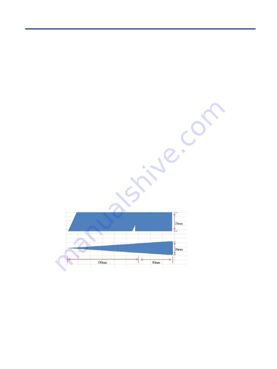
Scraper bar in the following dimensions: 


Rear Cover


Before removing the Rear Cover, follow these steps: 

▲ 

Prepare the monitor for disassembly. See Preparation for disassembly on page 12. 

1)


Pull the  release button to remove Stand Base From Display Head 

Содержание Z27Q G3

Страница 1: ...Maintenance and Service Guide Z27q G3 model SUMMARY This guide provides information about spare parts removal and replacement of parts diagnostic tests problem troubleshooting and more ...

Страница 2: ...tates and other countries The information contained herein is subject to change without notice The only warranties for HP products and services are set forth in the express warranty statements accompanying such products and services Nothing herein should be construed as constituting an additional warranty HP shall not be liable for technical or editorial errors or omissions contained herein First ...

Страница 3: ...es 3 Features 3 Front components 5 Rear and side components 6 Locating the serial number and product number 7 3 Illustrated parts catalog 8 How to order parts 10 4 Removal and replacement procedures 12 Preparation for disassembly 12 Rear Cover 12 Power board 15 Connector repair 17 HDMI connector HDMI1 18 DP connector DP1 DP2 18 USB B connector USB1 19 USB A connector USB2 USB3 20 USB A connector U...

Страница 4: ...before opening the product s cabinet Modules containing electrical components are sensitive to electrostatic discharge ESD Follow ESD safety procedures while handling these parts Some products contain more than one battery Do not disassemble or expose a battery to high temperatures such as throwing into fire or the battery may explode Refer to government requirements for battery recycling or dispo...

Страница 5: ... Substance in Electrical and Electronic Equipment Directive is a legal requirement by the EU European Union for the global electronics industry sold in the EU and other countries Any electrical and electronics products launched in the market after June 2006 should meet this RoHS requirement Products launched in the market before June 2006 are not required to be compliant with RoHS parts If the ori...

Страница 6: ...Port andHDMI inputs to be viewed in each half of the screen select products only On screen display OSD adjustments in several languages for easy setup and screen optimization Color space presets for sRGB and BT 709 Energy saver feature to meet requirements for reduced power consumption Security cable slot on the rear of the monitor for an optional security cable Cable management feature for placem...

Страница 7: ...for attaching the monitor to a swing arm mount Support for a mounting bracket to attach the monitor to a workstation NOTE For safety and regulatory information refer to the Product Notices provided in your documentation kit To access the latest user guides or manuals for your product go to http www hp com support and follow the instructions to find your product Then select Manuals ...

Страница 8: ...5 Front components To identify the components on the front of the monitor use this illustration and table ...

Страница 9: ... source device such as a computer 7 DisplayPort connector OUT Connects the DisplayPort cable from the monitor to a secondary monitor 8 USB Type B port upstream Connects the USB Type B cable to a source device such as a computer This port enables the USB Type A ports to perform their functions 9 USB port Connects a USB cable to a peripheral device such as a keyboard mouse or USB harddrive 10 USB po...

Страница 10: ...mber The serial number and product number are located on the rear of the monitor You may need these numbers when contacting HP about the monitor model For worldwide models except India Barcode label Spec label For India Barcode label Spec label ...

Страница 11: ... 3 Illustrated parts catalog To identify the monitor major components use this illustration and table Table 3 1 Monitor major components and their descriptions Item Description Qty 1 ASSY Panel Z27q G3 1 ...

Страница 12: ...27q G3 1 15 Power Key Board Z27q G3 1 16 Screw Tapping None Flat 0 2mm Head 2 17 Screw M2 2 2 0 8T 4 18 Screw M2 2 8L 2 19 Rear Cover Z27q G3 1 20 Side USB Holder Z27q G3 1 21 Side USB Board Z27q G3 1 22 Screw Tap Pan M3 6 Ni 2 23 OSD Key Holder Z27q G3 1 24 OSD Board Z27q G3 1 25 Joystick Cap Z27q G3 1 26 Screw Tap Pan M3 6 Ni 2 27 Z Logo 48mm PET Black 1 28 Assy Hinge Z27q G3 1 29 Screw M4 6 FH ...

Страница 13: ...com Connectors by manufacturer Component description Location identifier Component distributor Distributer part number Remark HDMI HDMI1 Switchcraft Inc https www digikey com PN 137 RAHHD19TR ND Modify the rear cover I O metal and plastic DP DP1 DP2 Molex https www digikey com PN WM14328DKR ND 1 Only DP1 1 2 Modify the rear cover I O metal 3 Cut off the through hole USB A USB2 USB3 Molex https www...

Страница 14: ...ct match You can purchase cables from the HP part store at https partsurfer hp com Search aspx NOTE HP continually improves and changes product parts For complete and current information about supported parts for your computer go to http partsurfer com select your country or region and then follow the on screen instructions Internal and External Power Supplies are available for purchase from the f...

Страница 15: ...for disassembly 3 Identify the disassembly area 4 Check the position that the monitors are to be placed along with the number of monitors Prepare the area for material flow according to the disassembly layout 5 Be sure to have the following equipment and materials Press fixture Working table Screwdriver Knife Gloves Cleaning cloth ESD protection Scraper bar in the following dimensions Rear Cover B...

Страница 16: ...ve the hinge cover then Release the four screws from back bracket and remove the hinge then Loose all the hooks by hand for pulling the rear cover 3 Remove USB BD Screws to remove USB BD Remove the EMI gasket then loose the two hooks by hand then remove the cable ...

Страница 17: ...er from display head Remove three screws and loose three hooks by hand 6 Remove Bracket Assembly From Display Head disconnect all inside cable then remove the four screws from the back bracket 7 Remove bezel bottom ASSY from display head Remove five screws ...

Страница 18: ... Release the six screws for releasing the power board and interface board Power board The power board part number is 755 A3B02 0001 or 755 A3B02 0002 Before removing the power board follow these steps Prepare the monitor for disassembly See Preparation for disassembly on page 12 Remove the power board 1 The HP Z27q G3 power board connector position is as follows ...

Страница 19: ...16 CN801 Wistron P N 020 60171 0112 2 Locate the part number location on the board 3 Pin solder with soldering iron and absorber ...

Страница 20: ... Phone Jack connectors The connectors are on the main board board part number 7ZB A3B01 0010 The connector identifiers are as follows Connector Location HDMI HDMI1 DP DP1 DP2 USB B USB1 USB A USB2 USB3 USB A USB4 USB5 Before repairing connectors follow these steps Prepare the monitor for disassembly See Preparation for disassembly on page 12 ...

Страница 21: ...e pin 2 Use a hot air gun to melt the solder on the pins 3 Lift the HDMI connector from the PCB 4 Place the new component on the PCB Be sure that it matches the PCB footprint 5 Solder the new component DP connector DP1 DP2 Repair the DP connector 1 Use a soldering iron and a de soldering pump to remove as much solder as possible from the pin ...

Страница 22: ... 4 Place the new component on the PCB Be sure that it matches the PCB footprint 5 Solder the new component USB B connector USB1 Repair the USB B connector 1 Use a soldering iron and a de soldering pump to remove as much solder as possible from the pin 2 Lift the USB B connector from the PCB ...

Страница 23: ... the pin 2 Lift the USB A connector from the PCB 3 Place the new component on the PCB Be sure that it matches the PCB footprint 4 Solder the new component USB A connector USB4 USB5 Repair the USB A connector 1 Use a soldering iron and a de soldering pump to remove as much solder as possible from the pin 2 Lift the USB A connector from the PCB 3 Place the new component on the PCB Be sure that it ma...

Страница 24: ...olutions Table 4 2 Solving common problems Problem Possible cause Solution Screen is blank or video is flashing Power cord is disconnected Connect the power cord Monitor is turned off Power the power button NOTE If pressing the Power button has no effect press and hold the power button for 10 seconds to disable the Power button lockout feature Master power switch is set to off Set the master power...

Страница 25: ...ut Signal Out of Range is displayed on screen Video resolution and or refresh rate are set higher than what the monitor supports Change the settings to a supported setting The monitor does not enter into a low power sleep state The monitor s power saving control is disabled Open the OSD menu and select Power select Auto Sleep Mode and set auto sleep to On OSD Lockout is displayed The monitor s OSD...

Страница 26: ...ts 8 parts ordering 10 power board removal 15 precautions 1 preparation for disassembly 12 RC removal 12 rear components 6 removal power board 15 RC 12 removal and replacement procedures 12 returning to customer 2 RoHS 2002 95 EC requirements 2 safety information 1 serial number location 7 service information 1 spare parts 8 support and troubleshooting 21 troubleshooting 21 ...

Отзывы: