


B-45
4.
Pull the CPU Assembly straight out and place on a flat surface
with an antistatic mat.
5.
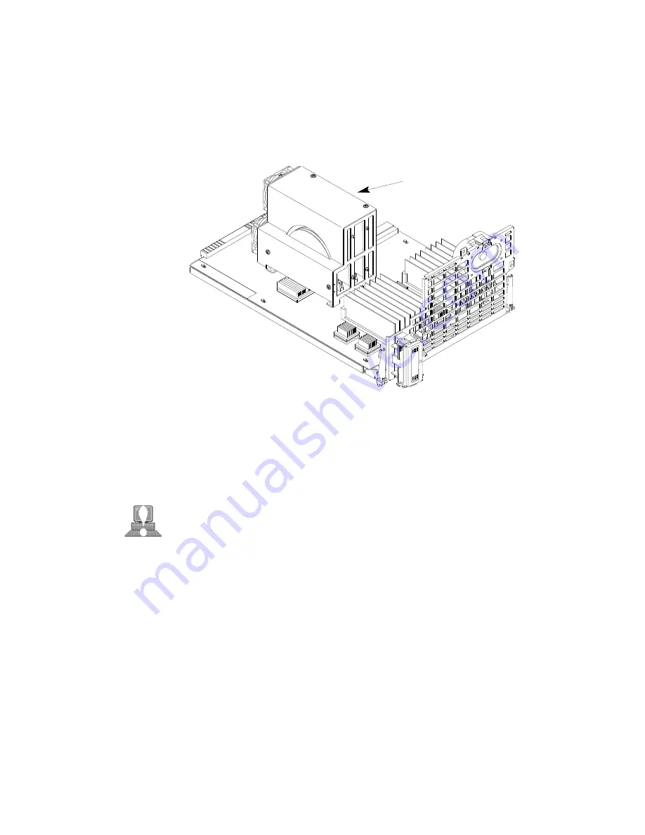
Locate the CPU shroud as shown in Figure A–26.
CPU shroud
Figure A–26. CPU Shroud Location
6.
Disconnect the fan cable from the system board. Refer to Figure
A–27.
CAUTION: Be sure to reconnect the fan cable when you
have finished installing the processor. Failure to
reconnect the fan could cause the unit to over-
head and damage the processor(s).
7.
Remove the six screws attaching the CPU shroud to the system
board and pull the shroud straight up. Set the shroud aside.
Содержание Visualize J5000
Страница 1: ...J Class Owner s Guide Workstation Systems Group HP Part No A4476 90013 Edition E0596 Printed in U S A ...
Страница 3: ...xiii Preface ...
Страница 18: ...xii ...
Страница 27: ...1 9 Removable Device Bays 2 Figure 1 3 System Unit with Removable Device Door Open ...
Страница 67: ...3 8 5 Gently push the disc tray in until it is closed as shown in Figure 6 4 Figure 6 4 Disc Tray Closed ...
Страница 150: ...B 22 ÅÅ ÅÅ ÅÅ ÅÅ Top View of Floppy Disk Drive 1 2 3 SCSI Terminators Figure A 11 Floppy Drive Terminators ...
Страница 156: ...B 28 6 5 4 3 2 1 0 15 14 13 12 11 10 9 8 Figure A 15 Fast Wide Hard Drive Jumper Settings ...
Страница 157: ...B 29 PCB Side of Drive Top Drive Bottom Drive Figure A 16 Replacing Hard Drive Mounting Bracket and Drive Orientation ...
Страница 185: ...B 57 7 Insert cover in guide and secure with screw Refer to Figure A 37 Figure A 37 Replacing EISA Assembly Cover ...
Страница 190: ...A 2 ...
Страница 216: ...C 22 Figure C 1 Rear Panel SCSI Connectors with Terminators Attached ...
Страница 271: ...Index 5 0 N 0 O 0 0 P 0 ...
Страница 273: ...Index 7 0 0 0 0 0 0 0 0 0 0 0 See 0 0 0 0 0 0 T 0 See also 0 U 0 V W ...


