


52
Chapter 3
Installing and Configuring
Changing Jumper/Dip Switch Settings after Processor Upgrade
When you upgrade from a 400 MHz processor to a 533 MHz processor, after installing the new processor you
must change a dip switch setting and move the jumper switch position (see
Figure 3-28
).
1. Remove the old processor (400 MHz) and replace it with the upgrade processor (533MHz). See
“Removing
the Processor”
and
“Replacing the Processor”
in
Chapter 7‚ Replacing Parts
.
2. On the system board, locate the Reserved Switch set and move switch 4 to the Off position. See
Figure 3-25
and
Figure 3-27
.
3. Using your thumbnail, carefully lift and remove the jumper switch from its socket (see
Figure 3-28
).
4. Replace the jumper switch on pins one and two of the jumper switch socket (see
Figure 3-28
)
The jumper switch must be on pins one and two for a 533 MHz processor (for a 400 MHz processor the
jumper switch is on pins two and three).
5. Replace the heat sink and cooling fan. See
“Replacing the Heat Sink and Cooling Fan”
in
Chapter 7‚
Replacing Parts
.
6. Replace the left side cover.
7. Replace the external cables and power cord.
8. Power on the server as described in
Chapter 1‚ Controls and Indicators
.
You may need to reboot the server for the BIOS to recognize the new processor.
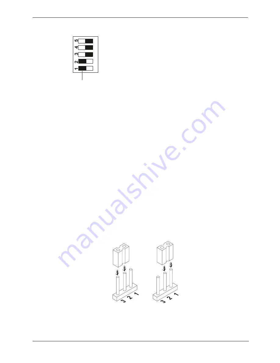
Figure 3-27. Reserved Switch Positions
Figure 3-28. Moving the Jumper Switch
Reserved (Do not change default setting)
Reserved (Do not change default setting)
Reserved (Do not change default setting)
On for 400 MHz processor, Off for 533 MHz processor
Reserved (Do not change default setting)
On (black indicates switch setting)


