background image

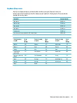
Keyboard/top cover

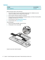
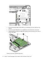
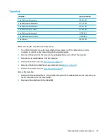
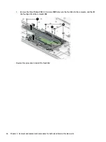
The top cover/keyboard spare part remains after all other spare parts have been removed.

In this section, the first table provides the main spare part number for the keyboards. The second table 
provides the country codes.

Description

Spare part number

Blue models

905569-xx1

White models

910180-xx1

Gray models

933583-xx1

Pink models

L16698-xx1

Purple models

L16699-xx1

Jet black models (only available for -001 United States)

928419-001

For use in country 
or region

Spare 
part 
number


For use in country 
or region

Spare 
part 
number


For use in country 
or region

Spare 
part 
number

Belgium

-A41


Hungary

-211


Saudi Arabia

-171

Bulgaria

-261


Israel

-BB1


Slovenia

-BA1

Canada

-DB1


Italy

-061


Spain

-071

Czech Republic 
and Slovakia

-FL1


Latin America

-161


Switzerland

-BG1

Denmark, Finland, and 
Norway

-DH1


The Netherlands

-B31


Turkey

-141

France

-051


Portugal

-131


United Kingdom

-031

Germany

-041


Romania

-271


United States

-001

Greece

-151


Russia

-251


Component replacement procedures

45

Содержание Stream PC 14-ax1 Series

Страница 1: ...HP Stream Laptop PC 14 Maintenance and Service Guide IMPORTANT This document is intended for HP authorized service providers only ...

Страница 2: ...2018 Document Part Number L19440 001 Product notice This guide describes features that are common to most models Some features may not be available on your computer Not all features are available in all editions of Windows This computer may require upgraded and or separately purchased hardware drivers and or software to take full advantage of Windows functionality See http www microsoft com for de...

Страница 3: ... another hard surface such as an adjoining optional printer or a soft surface such as pillows or rugs or clothing to block airflow Also do not allow the AC adapter to contact the skin or a soft surface such as pillows or rugs or clothing during operation The device and the AC adapter comply with the user accessible surface temperature limits defined by the International Standard for Safety of Info...

Страница 4: ...iv Safety warning notice ...

Страница 5: ...play assembly components 17 Miscellaneous parts 18 4 Removal and replacement procedures preliminary requirements 19 Tools required 19 Service considerations 19 Plastic parts 19 Cables and connectors 19 Electrostatic discharge damage 20 Packaging and transporting guidelines 21 Workstation guidelines 21 Equipment guidelines 22 5 Removal and replacement procedures for Authorized Service Provider part...

Страница 6: ...r to create recovery media 49 Before you begin 49 Creating the recovery media 50 Using the HP Cloud Recovery Download Tool to create recovery media 50 Restoring and recovery 50 Restoring resetting and refreshing using Windows tools 50 Restoring using HP Recovery Manager and the HP Recovery partition 50 Recovering using HP Recovery Manager 51 Recovering using the HP Recovery partition select produc...

Страница 7: ... or number select products only 55 Using Remote HP PC Hardware Diagnostics UEFI settings select products only 56 Downloading Remote HP PC Hardware Diagnostics UEFI 56 Downloading the latest Remote HP PC Hardware Diagnostics UEFI version 56 Downloading Remote HP PC Hardware Diagnostics UEFI by product name or number 56 Customizing Remote HP PC Hardware Diagnostics UEFI settings 56 9 Specifications ...

Страница 8: ...viii ...

Страница 9: ... FHD 1920 1080 BrightView light emitting diode LED UWVA slim flat 3 0 mm eDP 220 nits Memory On board system memory DDR4 2400MHz single channel support Supports up to 2 GB maximum on board system memory One SODIMM slot non accessible non upgradeable DDR4 2400MHz single channel support Supports up to 4 GB maximum system memory Hard drive eMMC configuration 64 MB 32 MB Optical drive External 9 5 mm ...

Страница 10: ...ophone combo jack High definition multimedia interface HDMI v 1 4 supporting 1920 1080 at 60 Hz USB 3 0 2 USB 2 0 1 Keyboard pointing devices Keyboard Full size textured island keyboard no numeric keypad Standard keyboard 1 5 mm travel distance TouchPad requirements TouchPad with image sensor Taps enabled as default Multitouch gestures enabled Default on for 2 finger scroll pinch rotate 2 finger c...

Страница 11: ...Category Description For Emerging Market EM SL Windows 10 Home Value NB EM SL Compact Windows 10 Home Entry NB EM SL Compact Serviceability End user replaceable part AC adapter 3 ...

Страница 12: ...nent Description 1 AC adapter and battery light White The AC adapter is connected and the battery is fully charged Blinking white The AC adapter is disconnected and the battery has reached a low battery level Amber The AC adapter is connected and the battery is charging Off The battery is not charging 2 Power connector Connects an AC adapter 4 Chapter 2 Getting to know your computer ...

Страница 13: ...ack does not support optional standalone microphones WARNING To reduce the risk of personal injury adjust the volume before putting on headphones earbuds or a headset For additional safety information refer to the Regulatory Safety and Environmental Notices To access this guide Select the Start button select HP Help and Support and then select HP Documentation NOTE When a device is connected to th...

Страница 14: ...LAN antennas 1 or 2 depending on model Send and receive wireless signals to communicate with wireless local area networks WLANs The antennas are not visible from the outside of the computer For optimal transmission keep the areas immediately around the antennas free from obstructions For wireless regulatory notices see the section of the Regulatory Safety and Environmental Notices that applies to ...

Страница 15: ...ne Reads your finger gestures to move the pointer or activate items on the screen 2 Left control zone Textured area that allows you to perform additional gestures 3 Right control zone Textured area that allows you to perform additional gestures Keyboard area 7 ...

Страница 16: ...ponent Description 1 Caps lock light On Caps lock is on which switches the key input to all capital letters 2 Mute light On Computer sound is off Off Computer sound is on 8 Chapter 2 Getting to know your computer ...

Страница 17: ...computer is in Hibernation press the button briefly to exit Hibernation CAUTION Pressing and holding down the power button results in the loss of unsaved information If the computer has stopped responding and shutdown procedures are ineffective press and hold the power button down for at least 5 seconds to turn off the computer To learn more about your power settings see your power options Right c...

Страница 18: ...fic functions when pressed in combination with another key 3 Windows key Opens the Start menu NOTE Pressing the Windows key again will close the Start menu 4 Action keys Execute frequently used system functions NOTE On select products the f5 action key turns the keyboard backlight feature off or on 10 Chapter 2 Getting to know your computer ...

Страница 19: ...g this key alternates the screen image from the computer display to the monitor display to a simultaneous display on both the computer and the monitor Mutes or restores speaker sound Decreases speaker volume incrementally while you hold down the key Increases speaker volume incrementally while you hold down the key Plays the previous track of an audio CD or the previous section of a DVD or a Blu r...

Страница 20: ...r inside the battery bay under the service door on the back of the display or on the bottom of a tablet kickstand Service label Provides important information to identify your computer When contacting support you may be asked for the serial number the product number or the model number Locate this information before you contact support Your service label will resemble one of the examples shown bel...

Страница 21: ... Serial number 4 Warranty period Regulatory label s Provide s regulatory information about the computer Wireless certification label s Provide s information about optional wireless devices and the approval markings for the countries or regions in which the devices have been approved for use Labels 13 ...

Страница 22: ...changes product parts For complete and current information on supported parts for your computer go to http partsurfer hp com select your country or region and then follow the on screen instructions Computer major components 14 Chapter 3 Illustrated parts catalog ...

Страница 23: ...WHr 3 615 AHr Li ion 844203 855 7 Battery cable 905566 001 8 Heat sink 907105 001 9 WLAN module Intel Dual Band Wireless AC 7265 802 11 AC 2x2 WiFi Bluetooth 4 2 Combo Adapter non vPro D1 901229 855 Realtek RTL8822BE 802 11 ac 2x2 WiFi Bluetooth 4 2 Combo Adapter MU MIMO supported 924813 855 10 Speakers includes cable 905565 001 11 System board includes a graphics subsystem with UMA memory thermal...

Страница 24: ...33581 001 For use in pink models L16701 001 For use in purple models L16706 001 Memory module 4 GB DDR4 2666 MHz not illustrated L10598 855 Rubber Kit Item Description Spare part number Rubber Kit For use in blue models 905567 001 For use in white models 910179 001 For use in black models 928420 001 For use in gray models 933607 001 For use in pink models L16704 001 For use in purple models L16709...

Страница 25: ...16702 001 For use in purple models L16707 001 2 Raw display panel HD panel 847664 005 FHD panel 847660 010 3 Webcam microphone module 766523 025 4 Display Hinge Kit includes left and right display hinges 905560 001 5 Display panel cable 905561 001 6 Antenna Kit includes wireless antenna cable with transceiver 906173 001 7 Display back cover For use in blue models 905558 001 For use in white models...

Страница 26: ...9941 001 HP USB external DVD RW DL SuperMulti Drive 747080 001 Power cord 3 pin black 1 00 m Argentina 401300 007 Australia 213356 008 Denmark 213353 008 Europe 213350 009 Israel 398063 003 Italy 213352 008 North America 213349 009 Switzerland 213354 008 The United Kingdom and Singapore 213351 008 Rubber Kit includes top and bottom rubber feet strips For use in blue models 905567 001 For use in wh...

Страница 27: ...nd reassembly can damage plastic parts Use care when handling the plastic parts Apply pressure only at the points designated in the maintenance instructions Cables and connectors CAUTION When servicing the tablet be sure that cables are placed in their proper locations during the reassembly process Improper cable placement can damage the tablet Cables must be handled with extreme care to avoid dam...

Страница 28: ... in their electrostatic safe containers until you are ready to install them Before touching an electronic component discharge static electricity by using the guidelines described in this section Avoid touching pins leads and circuitry Handle electronic components as little as possible If you remove a component place it in an electrostatic safe container The following table shows how humidity affec...

Страница 29: ...d and that proper materials are selected to avoid static charging When grounding is not possible use an ionizer to dissipate electric charges Workstation guidelines Follow these grounding workstation guidelines Cover the workstation with approved static shielding material Use a wrist strap connected to a properly grounded work surface and use properly grounded tools and equipment Use conductive fi...

Страница 30: ...operator and ground To be effective the conductive must be worn in contact with the skin The following grounding equipment is recommended to prevent electrostatic damage Antistatic tape Antistatic smocks aprons and sleeve protectors Conductive bins and other assembly or soldering aids Nonconductive foam Conductive tabletop workstations with ground cords of one megohm resistance Static dissipative ...

Страница 31: ...n page 12 for details NOTE HP continually improves and changes product parts For complete and current information on supported parts for your computer go to http partsurfer hp com select your country or region and then follow the on screen instructions Component replacement procedures This chapter provides removal and replacement procedures for Authorized Service Provider only parts There are as m...

Страница 32: ... on and then shut it down through the operating system 2 Disconnect the power from the computer by unplugging the power cord from the computer 3 Disconnect all external devices from the computer Remove the bottom cover 1 Position the computer upside down 2 Peel the two rubber strips off the bottom cover 1 to gain access to the screws underneath 3 Remove eight Phillips PM2 5 6 0 screws 2 that secur...

Страница 33: ...he power cord from the AC outlet and then unplugging the AC adapter from the computer 4 Remove the bottom cover see Bottom cover on page 24 Remove the battery 1 Disconnect the battery cable from the system board 1 2 Remove the three PM2 0 2 5 screws 2 that secure the battery to the computer 3 Remove the two PM2 0 6 0 screws 3 that secure the connector to the computer 4 Lift the battery and the con...

Страница 34: ...er by first unplugging the power cord from the AC outlet and then unplugging the AC adapter from the computer 4 Remove the bottom cover see Bottom cover on page 24 5 Disconnect the battery cable from the system board see Battery on page 25 To remove a memory module 1 Spread the retaining tabs 1 on each side of the memory module slot to release the memory module The memory module tilts up 2 Remove ...

Страница 35: ... computer If you are unsure whether the computer is off or in Hibernation turn the computer on and then shut it down through the operating system 2 Disconnect all external devices connected to the computer 3 Disconnect the power from the computer by first unplugging the power cord from the AC outlet and then unplugging the AC adapter from the computer 4 Remove the bottom cover see Bottom cover on ...

Страница 36: ... antenna is not connected to the terminal on the WLAN module a protective sleeve must be installed on the antenna connector as shown in the following illustration Reverse this procedure to install the WLAN module 28 Chapter 5 Removal and replacement procedures for Authorized Service Provider parts ...

Страница 37: ...onnect the power from the computer by first unplugging the power cord from the AC outlet and then unplugging the AC adapter from the computer 4 Remove the bottom cover see Bottom cover on page 24 5 Disconnect the battery cable from the system board see Battery on page 25 To remove the RTC battery Disconnect the RTC battery cable from the system board 1 and then lift the RTC battery from the comput...

Страница 38: ...the AC adapter from the computer 4 Remove the bottom cover see Bottom cover on page 24 5 Disconnect the battery cable from the system board see Battery on page 25 Remove the heat sink 1 Remove the two Phillips broad head PM2 0 2 0 screws 1 that secure the heat sink to the system board 2 Lift the heat sink off the system board 2 NOTE The thermal material must be thoroughly cleaned from the surfaces...

Страница 39: ...Reverse this procedure to install the heat sink Component replacement procedures 31 ...

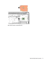
Страница 40: ...connected to the computer 3 Disconnect the power from the computer by first unplugging the power cord from the AC outlet and then unplugging the AC adapter from the computer 4 Remove the bottom cover see Bottom cover on page 24 5 Remove the battery see Battery on page 25 Remove the speakers 1 Disconnect the speaker cable 1 from the system board 2 Lift the speakers from the computer 2 Reverse this ...

Страница 41: ...ting system L16637 601 Before removing the system board follow these steps 1 Shut down the computer If you are unsure whether the computer is off or in Hibernation turn the computer on and then shut it down through the operating system 2 Disconnect all external devices connected to the computer 3 Disconnect the power from the computer by first unplugging the power cord from the AC outlet and then ...

Страница 42: ...Phillips PM2 0 2 5 screws 2 that secure the system board to the computer 4 Lift up the left side of the system board 3 and then pull the system board toward the left to remove it from the computer 4 Reverse this procedure to install the system board 34 Chapter 5 Removal and replacement procedures for Authorized Service Provider parts ...
Страница 43: ...in Hibernation turn the computer on and then shut it down through the operating system 2 Disconnect the power from the computer by unplugging the power cord from the computer 3 Disconnect all external devices from the computer 4 Remove the bottom cover see Bottom cover on page 24 5 Disconnect the battery cable from the system board see Battery on page 25 6 Remove the system board see System board ...

Страница 44: ...0 3 0 screws 4 that secure the TouchPad to the computer and the lift the Touchpad from the computer 5 Reverse this procedure to install the TouchPad 36 Chapter 5 Removal and replacement procedures for Authorized Service Provider parts ...

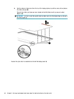
Страница 45: ...ver on page 24 5 Disconnect the battery cable from the system board see Battery on page 25 Remove the display assembly 1 Remove the WLAN antennas from the routing path in the computer 1 2 Remove the four Phillips PM2 5 5 0 screws 2 that secure the display assembly to the computer 3 Lift the display assembly from the computer 3 4 If it is necessary to replace the display bezel a Flex the inside edg...

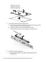
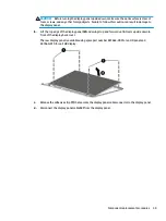
Страница 46: ...ached to the display back cover with double sided adhesive b Disconnect the webcam microphone module cable 2 from the module The webcam microphone module is available using spare part number 766523 025 6 If it is necessary to replace the display panel a Remove the four Phillips PM2 0 3 0 screws 1 that secure the display panel to the display back cover 38 Chapter 5 Removal and replacement procedure...

Страница 47: ...of the display panel 2 and swing it up and forward until it rests upside down in front of the display back cover The raw display panel is available using spare part number 847664 005 for an HD panel and 847660 010 for an FHD display c Release the adhesive strip 1 that secures the display panel cable connector to the display panel d Disconnect the display panel cable 2 from the display panel Compon...

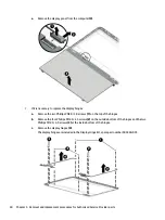
Страница 48: ...inges b Remove the four Phillips PM2 5 2 5 screws 2 on the outside bottom of the hinges and the two Phillips PM2 5 4 0 screws 3 at the inside bottom of the hinges c Remove the display hinges 4 The display hinges are included in the Display Hinge Kit spare part number 905560 001 40 Chapter 5 Removal and replacement procedures for Authorized Service Provider parts ...

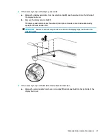
Страница 49: ... cable includes the webcam microphone module cable and is available using spare part number 905561 001 IMPORTANT Be sure to note the way the cable routes into the display hinge as shown in the following image 9 If it is necessary to replace the WLAN antenna cable and transceiver a Release the antenna cable from the retention clips 1 and channel built into the right side of the display back cover C...

Страница 50: ...ansceivers are included in the WLAN Antenna Kit spare part number 906173 001 IMPORTANT Be sure to note the way the antenna cable routes into the display hinge as shown in the following image Reverse this procedure to reassemble and install the display assembly 42 Chapter 5 Removal and replacement procedures for Authorized Service Provider parts ...

Страница 51: ...plugging the power cord from the computer 3 Disconnect all external devices from the computer 4 Remove the bottom cover see Bottom cover on page 24 5 Disconnect the battery cable from the system board see Battery on page 25 6 Remove the display assembly see Display assembly on page 37 Remove the power button board 1 Disconnect the cable from the power button board 1 2 Remove the PM2 0 3 0 screw 2 ...

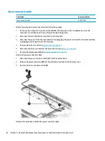
Страница 52: ...wer cord from the AC outlet and then unplugging the AC adapter from the computer 4 Remove the bottom cover see Bottom cover on page 24 5 Disconnect the battery cable from the system board see Battery on page 25 6 Remove the display assembly see Display assembly on page 37 Remove the power connector cable 1 Disconnect the power connector cable 1 from the system board 2 Release the power connector 2...

Страница 53: ... Jet black models only available for 001 United States 928419 001 For use in country or region Spare part number For use in country or region Spare part number For use in country or region Spare part number Belgium A41 Hungary 211 Saudi Arabia 171 Bulgaria 261 Israel BB1 Slovenia BA1 Canada DB1 Italy 061 Spain 071 Czech Republic and Slovakia FL1 Latin America 161 Switzerland BG1 Denmark Finland an...

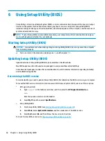
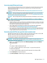
Страница 54: ... the HP website Most BIOS updates on the HP website are packaged in compressed files called SoftPaqs Some download packages contain a file named Readme txt which contains information regarding installing and troubleshooting the file Determining the BIOS version To decide whether you need to update Setup Utility BIOS first determine the BIOS version on your computer To reveal the BIOS version infor...

Страница 55: ...ntify the most recent BIOS update and compare it to the BIOS version currently installed on your computer If the update is more recent than your BIOS version make a note of the date name or other identifier You may need this information to locate the update later after it has been downloaded to your hard drive b Follow the on screen instructions to download your selection to the hard drive Make a ...

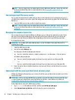
Страница 56: ...information loss You can use Windows tools to back up personal information and create system restore points and recovery media allowing you to restore from backup refresh the computer and reset the computer to its original state NOTE If computer storage is 32 GB or less Microsoft System Restore is disabled by default Creating backups You can create recovery media system restore points and backups ...

Страница 57: ... safe place HP Recovery Manager examines the computer and determines the required media storage capacity To create recovery media use one of the following options NOTE If the computer does not have a recovery partition HP Recovery Manager displays the Windows Create a Recovery Drive feature Follow the on screen instructions to create a recovery image on a blank USB flash drive or hard drive If you...

Страница 58: ...covery Manager and the HP Recovery partition select products only to restore the computer to the original factory state Resolving problems with preinstalled applications or drivers To correct a problem with a preinstalled application or driver 1 Type recovery in the taskbar search box and then select HP Recovery Manager 2 Select Reinstall drivers and or applications and then follow the on screen i...

Страница 59: ...ed This media is created using HP Recovery Manager See Creating HP Recovery media select products only on page 49 If your computer does not allow the creation of HP Recovery media or if the HP Recovery media does not work contact support to obtain recovery media Go to http www hp com support select your country or region and then follow the on screen instructions Recovering using the HP Recovery p...

Страница 60: ...etachable keyboard connect the tablet to the keyboard base before beginning these steps 1 Insert the HP Recovery media 2 Access the system Startup menu For computers or tablets with keyboards attached Turn on or restart the computer or tablet quickly press esc and then press f9 for boot options For tablets without keyboards Turn on or restart the tablet quickly hold down the volume up button and t...

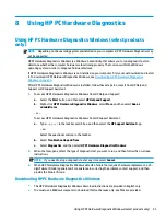
Страница 61: ...t HP Help and Support b Right click HP PC Hardware Diagnostics Windows select More and then select Run as administrator or To access HP PC Hardware Diagnostics Windows from HP Support Assistant a Type support in the taskbar search box and then select the HP Support Assistant app or Select the question mark icon in the taskbar b Select Troubleshooting and fixes c Select Diagnostics and then select ...

Страница 62: ...ate to the folder on your computer or the flash drive where the exe file was downloaded double click the exe file and then follow the on screen instructions Using HP PC Hardware Diagnostics UEFI NOTE For Windows 10 S computers you must use a Windows computer and a USB flash drive to download and create the HP UEFI support environment because only exe files are provided For more information see Dow...

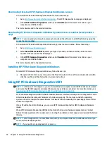
Страница 63: ...agnostics UEFI is not included in the preinstall image HP PC Hardware Diagnostics UEFI is not included in the HP Tool partition The hard drive is damaged NOTE The HP PC Hardware Diagnostics UEFI download instructions are provided in English only and you must use a Windows computer to download and create the HP UEFI support environment because only exe files are provided Downloading the latest HP P...

Страница 64: ...ion select Download Remote Diagnostics and then select Run Downloading Remote HP PC Hardware Diagnostics UEFI by product name or number NOTE For some products it may be necessary to download the software by using the product name or number To download HP Remote PC Hardware Diagnostics UEFI by product name or number follow these steps 1 Go to http www hp com support 2 Select Get software and driver...

Страница 65: ...iagnostics UEFI settings follow these steps 1 Turn on or restart the computer and when the HP logo appears press f10 to enter Computer Setup 2 Select Advanced and then select Settings 3 Make your customization selections 4 Select Main and then Save Changes and Exit to save your settings Your changes take effect when the computer restarts Using Remote HP PC Hardware Diagnostics UEFI settings select...

Страница 66: ...mperature Operating 5 C to 35 C 41 F to 95 F Nonoperating 20 C to 60 C 4 F to 140 F Relative humidity noncondensing Operating 10 to 90 Nonoperating 5 to 95 Maximum altitude unpressurized Operating 15 m to 3 048 m 50 ft to 10 000 ft Nonoperating 15 m to 12 192 m 50 ft to 40 000 ft NOTE Applicable product safety standards specify thermal limits for plastic surfaces The device operates well within th...

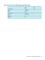
Страница 67: ...ecifications Metric U S Active diagonal size 35 56 cm 14 0 in Resolution 1366x768 HD Width 3 0 mm Surface treatment BrightView Brightness 220 nits typical Viewing angle SVA Backlight LED 35 56 cm 14 0 in HD display specifications 59 ...

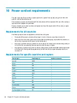
Страница 68: ...roved by an acceptable accredited agency responsible for evaluation in the country or region where the power cord set will be used The power cord sets must have a minimum current capacity of 10 amps and a nominal voltage rating of 125 or 250 V AC as required by the power system of each country or region The appliance coupler must meet the mechanical configuration of an EN 60 320 IEC 320 Standard S...

Страница 69: ...ord and wall plug must bear a T mark and registration number in accordance with the Japanese Dentori Law The flexible cord must be Type VCT or VCTF 3 conductor 1 00 mm conductor size The wall plug must be a two pole grounding type with a Japanese Industrial Standard C8303 7 A 125 V configuration 4 The flexible cord must be Type RVV 3 conductor 0 75 mm conductor size Power cord set fittings applian...

Страница 70: ...in general household waste Follow the local laws and regulations in your area for battery disposal HP encourages customers to recycle used electronic hardware HP original print cartridges and rechargeable batteries For more information about recycling programs see the HP Web site at http www hp com recycle 62 Chapter 11 Recycling ...

Страница 71: ...5 right side 4 computer major components 14 specifications 58 connector power 4 connectors service considerations 19 control zone 7 D display assembly removal 37 spare part numbers 17 display back cover spare part number 17 display bezel removal 37 spare part number 17 37 display components 6 Display Hinge Kit spare part number 17 40 display panel product description 1 removal 38 spare part number...

Страница 72: ...siderations 19 play action key 11 ports HDMI 5 product description 2 USB 5 USB SuperSpeed 5 power button board removal 43 spare part number 16 43 power button board cable spare part number 16 43 power button identifying 9 power connector identifying 4 power connector cable removal 44 spare part number 16 44 power cord set requirements 60 power lights identifying 5 power requirements product descri...

Страница 73: ...sing 10 specifications display 59 supported discs recovery 49 switch screen image action key 11 system board removal 33 spare part numbers 33 system recovery 51 system restore point creating 48 T tools required 19 TouchPad removal 35 spare part number 15 35 TouchPad cable spare part number 15 35 TouchPad zone identifying 7 transporting guidelines 21 traveling with the computer 13 U USB port identi...

Отзывы: