background image

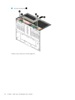
Reverse this procedure to install the lower frame.

Hinges

Description

Spare part number

Hinges (2, includes left and right hinges)

L38690-001

Before removing the hinges, follow these steps:

1.

Shut down the computer. If you are unsure whether the computer is off or in Hibernation, turn 
the computer on, and then shut it down through the operating system.

2.

Disconnect all external devices connected to the computer.

3.

Disconnect the power from the computer by first unplugging the power cord from the AC outlet, and then 
unplugging the AC adapter from the computer.

4.

Remove the display panel (see 

Display panel on page 25

), and then remove the following components:

a.

Webcam (see 

Webcam on page 36

)

b.

Leather cover (see 

Leather cover on page 41

)

c.

Speaker assembly (see 

Speaker assembly on page 46

)

d.

Keyboard (see 

Keyboard on page 49

)

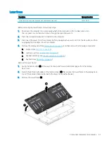
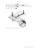
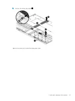
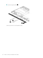
Remove the hinges:

1.

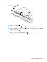
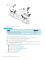
Remove the four screw covers (1) that conceal the hinge cover screws.

NOTE:

The screw covers are included in the Mylar/Rubber/Tape Kit, spare part number L38695-001.

2.

Remove the four Phillips M2.0×4.4 screws (2) that secure the hinge cover to the lower frame.

NOTE:

The hinge cover is available using spare part numbers L38689-001 (for use only on computer 

models equipped with WLAN) and L38688-001 (for use only on computer models equipped with WWAN).

52

Chapter 5   Removal and replacement procedures

Содержание Spectre Folio

Страница 1: ...Maintenance and Service Guide HP Spectre Folio 13 Convertible PC IMPORTANT This document is intended for HP authorized service providers only ...

Страница 2: ...ot be available on your computer Not all features are available in all editions or versions of Windows Systems may require upgraded and or separately purchased hardware drivers software or BIOS update to take full advantage of Windows functionality Windows 10 is automatically updated which is always enabled ISP fees may apply and additional requirements may apply over time for updates Go to http w...

Страница 3: ... another hard surface such as an adjoining optional printer or a soft surface such as pillows or rugs or clothing to block airflow Also do not allow the AC adapter to contact the skin or a soft surface such as pillows or rugs or clothing during operation The device and the AC adapter comply with the user accessible surface temperature limits defined by the International Standard for Safety of Info...

Страница 4: ...iv Safety warning notice ...

Страница 5: ...ed parts catalog 13 Computer major components 13 Miscellaneous parts 17 4 Removal and replacement procedures preliminary requirements 19 Tools required 19 Service considerations 19 Plastic parts 19 Cables and connectors 20 Drive handling 20 Electrostatic discharge damage 21 Packaging and transporting guidelines 22 Workstation guidelines 22 Equipment guidelines 23 5 Removal and replacement procedur...

Страница 6: ...tics Windows version 68 Downloading HP Hardware Diagnostics Windows by product name or number select products only 69 Installing HP PC Hardware Diagnostics Windows 69 Using HP PC Hardware Diagnostics UEFI 69 Starting HP PC Hardware Diagnostics UEFI 69 Downloading HP PC Hardware Diagnostics UEFI to a USB flash drive 70 Downloading the latest HP PC Hardware Diagnostics UEFI version 70 Downloading HP...

Страница 7: ...edia select products only 73 Restoring and recovery 74 Restoring resetting and refreshing using Windows tools 74 Recovering using HP Recovery media 74 Changing the computer boot order 74 9 Specifications 75 Computer specifications 75 10 Power cord set requirements 76 Requirements for all countries 76 Requirements for specific countries and regions 77 11 Recycling 79 Index 80 vii ...

Страница 8: ...viii ...
Страница 9: ... PSR2 ultraslim TouchScreen display panel with narrow bezel 13 3 in FHD 1920 1080 BrightView WLED UWVA 300 nits eDP PSR ultraslim TouchScreen display panel with narrow bezel All display panels feature direct bonding Memory System memory built into system board Support for LPDDR4X 2666 and LPDDR3 1866 system memory Support for up to 16 GB of system memory in the following configurations LPDDR4X 266...

Страница 10: ... assembly Support for Intel XMM 7560 LTE Advanced Pro WWAN module Ports Audio out headphone Audio in microphone combo jack USB Type C port 3 1 Gen 2 with Thunderbolt Gen 3 technology 2 USB Type C port 3 1 Gen 1 3 Power requirements Support for a 6 cell 54 28 WHr battery Support for 65 W AC adapter non PFC USB Type C 1 8 m slim straight and 65 W AC adapter non PFC USB Type C 1 8 m C6NS NP AC adapte...

Страница 11: ...ed on the computer Type device manager in the taskbar search box and then select the Device Manager app A list displays all the devices installed on the computer For information about system hardware components and the system BIOS version number press fn esc select products only Locating software To find out what software is installed on the computer Right click the Start button and then select Ap...

Страница 12: ...connectors and Thunderbolt ports with HP Sleep and Charge Connect an AC adapter that has a USB Type C connector supplying power to the computer and if needed charging the computer battery and Even when the computer is off connect and charge most USB devices that have a Type C connector such as a cell phone camera activity tracker or smartwatch and provides high speed data transfer when the system ...

Страница 13: ...ower connector and port with HP Sleep and Charge Connects an AC adapter that has a USB Type C connector supplying power to the computer and if needed charging the computer battery and Even when the computer is off charges most products such as a cell phone camera activity tracker or smartwatch and provides data transfer and Connects a display device that has a USB Type C connector providing Displa...

Страница 14: ... pen loop is included in the product box Follow the instructions on the pen loop label to install the pen loop NOTE Attach the loop to the plastic not the leather cover For more information about the pen see the documentation provided with the pen 6 WLAN antennas Send and receive wireless signals to communicate with wireless local area networks WLANs The antennas are not visible from the outside o...

Страница 15: ...on Keyboard area TouchPad Component Description 1 TouchPad zone Reads finger gestures to move the pointer or activate items on the screen 2 Left TouchPad button Functions like the left button on an external mouse 3 Right TouchPad button Functions like the right button on an external mouse Keyboard area 7 ...

Страница 16: ... saving state that shuts off power to the display and other unneeded components Hibernation is a power saving state that uses the least amount of power 2 Caps lock light On Caps lock is on which switches the key input to all capital letters 3 Mute light On Computer sound is off Off Computer sound is on 8 Chapter 2 External component identification ...

Страница 17: ...press the button briefly to exit Sleep select products only When the computer is in Hibernation press the button briefly to exit Hibernation CAUTION Pressing and holding down the power button results in the loss of unsaved information If the computer has stopped responding and shutdown procedures are ineffective press and hold the power button down for at least 5 seconds to turn off the computer 2...

Страница 18: ...c functions when pressed in combination with another key 3 Windows key Opens the Start menu NOTE Pressing the Windows key again will close the Start menu 4 Action keys Execute frequently used system functions NOTE On select products the f5 action key turns the keyboard backlight feature off or on 10 Chapter 2 External component identification ...

Страница 19: ...is flipped the leather is folded in half Service label Provides important information to identify the computer When contacting support the serial number product number or model number may be required Locate this information before contacting support Item Component 1 Model number 2 Product ID 3 Serial number 4 Warranty period Regulatory label s Provide s regulatory information about the computer Wi...

Страница 20: ...product name or number 2 Select Product Information 3 Refer to the listed options to determine which card to purchase To insert a SIM card follow these steps 1 Turn off the computer by using the Shut down command 2 Disconnect all external devices connected to the computer 3 Unplug the power cord from the AC outlet 4 Flip the panel leather cover 360 degrees to access the SIM card slot After the cov...

Страница 21: ...rted parts for the computer go to http partsurfer hp com select the appropriate country or region and then follow the on screen instructions NOTE Details about the computer including model serial number product key and length of warranty are on the service tag affixed to the computer See Labels on page 11 for more information Computer major components 13 ...

Страница 22: ...y panel 13 3 in BrightView WLED UWVA TouchScreen display panel with narrow bezel UHD 3840 2160 400 eDP PSR wedge display panel L38698 001 FHD 1920 1080 400 eDP 1 4 PSR2 ultraslim display panel L38696 001 14 Chapter 3 Illustrated parts catalog ...

Страница 23: ...8687 001 For use only on computer models equipped with WWAN L38686 001 8 Lower frame includes retention band with adhesive and magnets L43335 001 9 Lower frame cover included in the Mylar Rubber Tape Kit spare part number L38695 001 includes adhesive 10 Display panel cable includes audio jack cable For use only on computer models equipped with a UHD 3840 2160 400 eDP PSR wedge display panel L38681...

Страница 24: ...ating system L38708 001 Equipped with an Intel Core i7 8500Y 1 50 GHz turbo up to 4 20 GHz dual core processor 1866 MHz 4 0 MB L3 cache 5 W Intel HD Graphics 625 graphics subsystem with UMA memory 8 GB of system memory and the Windows 10 operating system L44606 601 Equipped with an Intel Core i7 8500Y 1 50 GHz turbo up to 4 20 GHz dual core processor 1866 MHz 4 0 MB L3 cache 5 W Intel HD Graphics ...

Страница 25: ...use in Taiwan L38709 AB1 For use in Thailand L38709 281 For use in Turkey L38709 141 For use in the United Kingdom L38709 031 For use in the United States L38709 001 23 WWAN Antenna Kit includes left and right WWAN antenna cables and transceivers L38671 001 24 Leather cover includes 6 cell battery and TouchPad IMPORTANT Do not clean the leather cover with alcohol It may discolor the leather For us...

Страница 26: ...ve stylus 920241 001 Pen loop L38685 001 Pen tip Cadillac Sunwoda L04536 001 Pen tip Impreza Sunwoda L04536 002 Impreza C to A cable L12232 001 Power cord C5 connector 1 00 m striker premium For use in Argentina L42493 001 For use in Australia L42486 001 For use in Denmark L42487 001 For use in Europe L42488 001 For use in India L42484 001 For use in Israel L42489 001 For use in Japan L42490 001 F...

Страница 27: ...wdrivers Suction cups Service considerations The following sections include some of the considerations that must kept in mind during disassembly and assembly procedures NOTE As each component is removed from the computer place the subassembly and all accompanying screws away from the work area to prevent damage Plastic parts CAUTION Using excessive force during disassembly and reassembly can damag...

Страница 28: ...nserting a hard drive shut down the computer If you are unsure whether the computer is off or in Hibernation turn the computer on and then shut it down through the operating system Before handling a drive be sure that you are discharged of static electricity While handling a drive avoid touching the connector Before removing an optical drive be sure that a disc is not in the drive and be sure that...

Страница 29: ...ons Keep components in their electrostatic safe containers until you are ready to install them Before touching an electronic component discharge static electricity by using the guidelines described in this section Avoid touching pins leads and circuitry Handle electronic components as little as possible If you remove a component place it in an electrostatic safe container The following table shows...

Страница 30: ...r materials are selected to avoid static charging When grounding is not possible use an ionizer to dissipate electric charges Workstation guidelines Follow these grounding workstation guidelines Cover the workstation with approved static shielding material Use a wrist strap connected to a properly grounded work surface and use properly grounded tools and equipment Use conductive field service tool...

Страница 31: ...m resistance between the operator and ground To be effective the conductive must be worn in contact with the skin The following grounding equipment is recommended to prevent electrostatic damage Antistatic tape Antistatic smocks aprons and sleeve protectors Conductive bins and other assembly or soldering aids Nonconductive foam Conductive tabletop workstations with ground cords of one megohm resis...

Страница 32: ...r void the warranty Component replacement procedures NOTE Details about your computer including model serial number product key and length of warranty are on the service tag at the bottom of your computer See Labels on page 11 for details NOTE HP continually improves and changes product parts For complete and current information on supported parts for your computer go to http partsurfer hp com sel...

Страница 33: ... it down through the operating system 2 Disconnect all external devices connected to the computer 3 Disconnect the power from the computer by first unplugging the power cord from the AC outlet and then unplugging the AC adapter from the computer Remove the display panel NOTE When using the heating gun in the following steps to dissolve the adhesive that secures the display assembly the heating gun...

Страница 34: ...t edges 4 of the display panel from the display back cover 8 Swing the top edge of the display panel 1 up and forward until it rests upside down in front of the computer 9 Release the security bar 2 on the display EDP cable and then disconnect the display EDP cable 3 from the transfer board 10 Release the zero insertion force ZIF connector 4 to which the transfer board cable is connected and then ...

Страница 35: ...the internal power button b Press the internal power button 2 to turn off power to the computer c Verify that power has been turned off by pressing the external power button NOTE The adhesive residue must be thoroughly cleaned from the surfaces of the display panel 1 and the display back cover 2 each time the display panel is removed Replacement adhesive is included with the display panel and the ...

Страница 36: ...43279 001 For use only on computer models equipped with WWAN L38678 001 Before removing the display EDP cable follow these steps 1 Shut down the computer If you are unsure whether the computer is off or in Hibernation turn the computer on and then shut it down through the operating system 2 Disconnect all external devices connected to the computer 28 Chapter 5 Removal and replacement procedures ...

Страница 37: ... the computer 4 Remove the display panel see Display panel on page 25 Remove the display EDP cable 1 Release the security bar 1 that secures the display EDP cable to the display panel 2 Disconnect the display EDP cable 2 from the display panel Reverse this procedure to install the display EDP cable Component replacement procedures 29 ...

Страница 38: ...AC adapter from the computer 4 Remove the display panel see Display panel on page 25 Remove the touch control board 1 Release the ZIF connectors 1 to which the touch control board cables are connected and then disconnect the touch control board cables 2 from the touch control board 2 If it is necessary to replace the touch control board cable release the ZIF connector 3 to which the touch control ...

Страница 39: ...er on and then shut it down through the operating system 2 Disconnect all external devices connected to the computer 3 Disconnect the power from the computer by first unplugging the power cord from the AC outlet and then unplugging the AC adapter from the computer 4 Remove the display panel see Display panel on page 25 Remove the WWAN module 1 Remove the Phillips M2 0 2 3 broad head screw 1 that s...

Страница 40: ...module 4 by pulling it away from the connector NOTE WWAN modules are designed with a notch to prevent incorrect insertion Reverse this procedure to install the WWAN module 32 Chapter 5 Removal and replacement procedures ...

Страница 41: ...nplugging the power cord from the AC outlet and then unplugging the AC adapter from the computer 4 Remove the display panel see Display panel on page 25 Remove the SIM card slot assembly 1 Release the ZIF connector 1 to which the SIM card slot assembly cable is connected and then disconnect the SIM card slot assembly cable from the transfer board 2 Remove the two Phillips M2 0 2 3 broad head screw...

Страница 42: ...nected to the computer 3 Disconnect the power from the computer by first unplugging the power cord from the AC outlet and then unplugging the AC adapter from the computer 4 Remove the display panel see Display panel on page 25 5 Remove the WWAN module see WWAN module on page 31 Remove the transfer board 1 Release the security bar 1 on the display panel cable and then disconnect the display panel c...

Страница 43: ...cam cables 3 and 4 from the transfer board 4 Remove the four Phillips M2 0 2 3 broad head screws 1 that secure the transfer board to the display back cover 5 Remove the transfer board 2 Component replacement procedures 35 ...

Страница 44: ...er cord from the AC outlet and then unplugging the AC adapter from the computer 4 Remove the display panel see Display panel on page 25 Remove the webcam 1 Disconnect the left webcam cable 1 from the transfer board 2 Release the left webcam cable from the retention clips 2 built into the display back cover 3 Disconnect the right webcam cable 3 from the transfer board 4 Release the right webcam cab...

Страница 45: ...rom the display back cover 7 The webcam is attached to the display back cover with adhesive 8 Remove the webcam bracket and cables Reverse this procedure to install the webcam and cables Component replacement procedures 37 ...

Страница 46: ...ect the power from the computer by first unplugging the power cord from the AC outlet and then unplugging the AC adapter from the computer 4 Remove the display panel see Display panel on page 25 5 Remove the webcam see Webcam on page 36 Remove the WWAN antenna 1 Release the left WWAN antenna cable from the retention clips 1 built into the display back cover 2 Release the right WWAN antenna cable f...

Страница 47: ... to the leather cover 5 Swing the top edge of the leather cover 1 down and back 6 Release the WWAN antenna cables through the openings 2 and 3 in the display back cover 7 Release the WWAN antenna cables through the openings 1 in the display back cover Component replacement procedures 39 ...

Страница 48: ...ther cover The WWAN antenna transceivers are attached to the leather cover with adhesive 9 Remove the WWAN antenna cables and transceivers Reverse this procedure to install the WWAN antenna cables and transceivers 40 Chapter 5 Removal and replacement procedures ...

Страница 49: ...connect the power from the computer by first unplugging the power cord from the AC outlet and then unplugging the AC adapter from the computer 4 Remove the display panel see Display panel on page 25 5 Remove the webcam see Webcam on page 36 Remove the leather cover 1 Swing the bottom edge of the display back cover up and forward until the rear panel is accessible 2 Rest the computer on its back as...

Страница 50: ... head screws that secure display back cover to the leather cover 5 Position the computer right side up with the front toward you 6 Swing the top edge of the display back cover 1 up and forward 2 42 Chapter 5 Removal and replacement procedures ...

Страница 51: ...panel toward you NOTE The rubber screw covers removed in the following step are different in size and shape Make note of which rubber screw cover was removed from which cavity 9 Remove the rubber screw covers 1 and 2 that conceal the display back cover screws NOTE The rubber screw covers are included in the Mylar Rubber Tape Kit spare part number L38695 001 Component replacement procedures 43 ...

Страница 52: ...g the top edge 2 of the keyboard and display back cover back and down until the battery cable ZIF connector and back light cable ZIF connector are accessible 13 Release the ZIF connector 1 to which the TouchPad cable is connected and then disconnect the TouchPad cable from the system board 14 Release the ZIF connector 2 to which the battery cable is connected and then disconnect the battery cable ...

Страница 53: ...15 Remove the keyboard and display back cover 3 from the leather cover Reverse this procedure to install the leather cover Component replacement procedures 45 ...

Страница 54: ...onnect the power from the computer by first unplugging the power cord from the AC outlet and then unplugging the AC adapter from the computer 4 Remove the display panel see Display panel on page 25 5 Remove the webcam see Webcam on page 36 6 Remove the leather cover see Leather cover on page 41 Remove the speaker assembly 1 Disconnect the speaker cables 1 from the system board 2 Remove the Phillip...

Страница 55: ... screw covers removed in the following step are different in size and shape Make note of which rubber screw cover was removed from which cavity 5 Remove the rubber screw covers 1 that conceal the speaker assembly screws NOTE The rubber screw covers are included in the Mylar Rubber Tape Kit spare part number L38695 001 6 Remove the two Phillips M2 0 3 4 screws 2 that secure the speaker assembly to ...

Страница 56: ...7 Remove the speaker assembly 3 Reverse this procedure to install the speaker assembly 48 Chapter 5 Removal and replacement procedures ...

Страница 57: ...09 291 For use in the United Kingdom L38709 031 For use in Latin America L38709 161 For use in the United States L38709 001 Before removing the keyboard follow these steps 1 Shut down the computer If you are unsure whether the computer is off or in Hibernation turn the computer on and then shut it down through the operating system 2 Disconnect all external devices connected to the computer 3 Disco...

Страница 58: ...4 Remove the keyboard 4 Reverse this procedure to install the keyboard 50 Chapter 5 Removal and replacement procedures ...

Страница 59: ... and then unplugging the AC adapter from the computer 4 Remove the display panel see Display panel on page 25 and then remove the following components a Webcam see Webcam on page 36 b Leather cover see Leather cover on page 41 c Speaker assembly see Speaker assembly on page 46 d Keyboard see Keyboard on page 49 Remove the lower frame 1 Swing the bottom edge 1 of the lower frame up and forward unti...

Страница 60: ...ove the display panel see Display panel on page 25 and then remove the following components a Webcam see Webcam on page 36 b Leather cover see Leather cover on page 41 c Speaker assembly see Speaker assembly on page 46 d Keyboard see Keyboard on page 49 Remove the hinges 1 Remove the four screw covers 1 that conceal the hinge cover screws NOTE The screw covers are included in the Mylar Rubber Tape...

Страница 61: ... the Phillips M2 0 2 3 broad head screw 3 that secures the left display hinge and the audio jack bracket to the lower frame 7 Remove the audio jack bracket 4 The audio jack bracket is available using spare part number xxx 8 Remove the three Phillips M2 0 2 3 broad head screws 5 that secure the display hinges to the lower frame Component replacement procedures 53 ...

Страница 62: ...n shut it down through the operating system 2 Disconnect all external devices connected to the computer 3 Disconnect the power from the computer by first unplugging the power cord from the AC outlet and then unplugging the AC adapter from the computer 4 Remove the display panel see Display panel on page 25 and then remove the following components a Webcam see Webcam on page 36 b Leather cover see ...

Страница 63: ...the retention clips 3 built into the lower frame 3 Detach the transfer board ribbon cable 4 from the lower frame The transfer board ribbon cable is attached to the lower frame with adhesive 4 Remove the transfer board cable 5 Reverse this procedure to install the transfer board cable Component replacement procedures 55 ...

Страница 64: ...uter 3 Disconnect the power from the computer by first unplugging the power cord from the AC outlet and then unplugging the AC adapter from the computer 4 Remove the display panel see Display panel on page 25 and then remove the following components a Webcam see Webcam on page 36 b Leather cover see Leather cover on page 41 c Speaker assembly see Speaker assembly on page 46 d Keyboard see Keyboard...

Страница 65: ...5 Remove the display panel cable 5 Reverse this procedure to install the display panel cable Component replacement procedures 57 ...

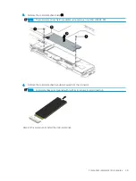
Страница 66: ...r the computer is off or in Hibernation turn the computer on and then shut it down through the operating system 2 Disconnect all external devices connected to the computer 3 Disconnect the power from the computer by first unplugging the power cord from the AC outlet and then unplugging the AC adapter from the computer 4 Remove the display panel see Display panel on page 25 5 Remove the webcam see ...

Страница 67: ...lable using spare part number L38682 001 4 Remove the solid state drive by pulling it away from the connector NOTE Solid state drives are designed with notches to prevent incorrect insertion Reverse this procedure to install the solid state drive Component replacement procedures 59 ...

Страница 68: ... Disconnect the power from the computer by first unplugging the power cord from the AC outlet and then unplugging the AC adapter from the computer 4 Remove the display panel see Display panel on page 25 5 Remove the webcam see Webcam on page 36 6 Remove the leather cover see Leather cover on page 41 Remove the power button board 1 Remove the Phillips M2 0 2 9 screw 1 that secures the power button ...

Страница 69: ...0 GHz turbo up to 4 20 GHz dual core processor 1866 MHz 4 0 MB L3 cache 5 W Intel HD Graphics 625 graphics subsystem with UMA memory 8 GB of system memory and a non Windows 10 operating system L44606 001 Equipped with an Intel Core i5 8200Y 1 30 GHz turbo up to 3 90 GHz dual core processor 1866 MHz 4 0 MB L3 cache 5 W Intel HD Graphics 625 graphics subsystem with UMA memory 8 GB of system memory a...

Страница 70: ...system board and the left and right I O brackets to the keyboard 4 Remove the Phillips M2 0 2 3 broad head screw 2 that secures the system board to the keyboard 5 Remove the left 3 and right I O brackets 4 NOTE The I O brackets are available using spare part number L38684 001 6 Lift the front edge of the system board 1 until it rests at an angle 62 Chapter 5 Removal and replacement procedures ...

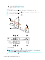
Страница 71: ...Heat sink Description Spare part number Heat sink 2 includes processor heat sink and graphics subsystem heat sink and replacement thermal material L39050 001 Before removing the heat sink follow these steps 1 Turn off the computer If you are unsure whether the computer is off or in Hibernation turn the computer on and then shut it down through the operating system 2 Disconnect the power from the c...

Страница 72: ...e the processor heat sink to the system board 3 Remove the processor heat sink 3 4 Remove the graphics subsystem heat sink 4 To install the heat sinks 1 Install the graphics subsystem heat sink 1 onto the system board NOTE When installing the graphics subsystem and processor heat sinks onto the system board make sure the metal clips 2 on the system board fully engage the heat sinks 2 Install the p...

Страница 73: ...four Phillips M2 0 2 9 screws 4 that secure the processor heat sink to the system board 4 Replace the adhesive foil strips 5 that secure the processor heat sink to the system board Component replacement procedures 65 ...

Страница 74: ...on the HP website Most BIOS updates on the HP website are packaged in compressed files called SoftPaqs Some download packages contain a file named Readme txt which contains information regarding installing and troubleshooting the file Determining the BIOS version To decide whether you need to update Setup Utility BIOS first determine the BIOS version on your computer To reveal the BIOS version inf...

Страница 75: ...entify the most recent BIOS update and compare it to the BIOS version currently installed on your computer If the update is more recent than your BIOS version make a note of the date name or other identifier You may need this information to locate the update later after it has been downloaded to your hard drive b Follow the on screen instructions to download your selection to the hard drive Make a...

Страница 76: ... search box and then select the HP Support Assistant app or Select the question mark icon in the taskbar b Select Troubleshooting and fixes c Select Diagnostics and then select HP PC Hardware Diagnostics Windows 2 When the tool opens select the type of diagnostic test you want to run and then follow the on screen instructions NOTE If you need to stop a diagnostic test at any time select Cancel 3 W...

Страница 77: ... HP UEFI support environment because only exe files are provided For more information see Downloading HP PC Hardware Diagnostics UEFI to a USB flash drive on page 70 HP PC Hardware Diagnostics UEFI Unified Extensible Firmware Interface allows you to run diagnostic tests to determine whether the computer hardware is functioning properly The tool runs outside the operating system so that it can isol...

Страница 78: ...go techcenter pcdiags The HP PC Diagnostics home page is displayed 2 In the HP PC Hardware Diagnostics UEFI section select Download UEFI Diagnostics and then select Run Downloading HP PC Hardware Diagnostics UEFI by product name or number select products only NOTE For some products it may be necessary to download the software to a USB flash drive by using the product name or number To download HP ...

Страница 79: ...ote UEFI version for the product Customizing Remote HP PC Hardware Diagnostics UEFI settings Using the Remote HP PC Hardware Diagnostics setting in Computer Setup BIOS you can perform the following customizations Set a schedule for running diagnostics unattended You can also start diagnostics immediately in interactive mode by selecting Execute Remote HP PC Hardware Diagnostics Set the location fo...

Страница 80: ...wnload Tool select products only to create recovery media see Using the HP Cloud Recovery Download Tool to create recovery media select products only on page 73 Restoring and recovery Windows offers several options for restoring from backup refreshing the computer and resetting the computer to its original state see Using Windows tools on page 73 IMPORTANT If you will be performing recovery proced...

Страница 81: ... then select the Get Help app 2 Enter the task you want to perform NOTE You must be connected to the Internet to access the Get Help app Using the HP Cloud Recovery Download Tool to create recovery media select products only You can use the HP Cloud Recovery Download Tool to create HP Recovery media on a bootable USB flash drive as follows 1 Go to http www hp com support 2 Select Software and Driv...

Страница 82: ...ging the computer boot order If your computer does not restart using the HP Recovery media you can change the computer boot order This is the order of devices listed in BIOS where the computer looks for startup information You can change the selection to an optical drive or a USB flash drive depending on the location of your HP Recovery media To change the boot order IMPORTANT For a tablet with a ...

Страница 83: ...ent 20 V dc 3 25 A 65 W 20 V dc 4 50 A 90 W 20 V dc 2 25 A 45 W Temperature Operating 5 C to 35 C 41 F to 95 F Nonoperating 20 C to 60 C 4 F to 140 F Relative humidity noncondensing Operating 10 to 90 Nonoperating 5 to 95 Maximum altitude unpressurized Operating 15 m to 3 048 m 50 ft to 10 000 ft Nonoperating 15 m to 12 192 m 50 ft to 40 000 ft NOTE Applicable product safety standards specify ther...

Страница 84: ...rements are applicable to all countries and regions The length of the power cord set must be at least 1 0 m 3 3 ft and no more than 2 0 m 6 5 ft All power cord sets must be approved by an acceptable accredited agency responsible for evaluation in the country or region where the power cord set will be used The power cord sets must have a minimum current capacity of 10 A and a nominal voltage rating...

Страница 85: ... KTL 5 Sweden SEMKO 1 Switzerland SEV 1 Taiwan BSMI 6 Thailand TISI 1 The United Kingdom ASTA 1 The United States UL 2 1 The flexible cord must be Type HO5VV F 3 conductor 0 75 mm conductor size Power cord set fittings appliance coupler and wall plug must bear the certification mark of the agency responsible for evaluation in the country or region where it will be used 2 The flexible cord must be ...

Страница 86: ...r the CCC certification mark 5 The flexible cord must be Type H05VV F 3 conductor 0 75 mm conductor size KTL logo and individual approval number must be on each element Corset approval number and logo must be printed on a flag label 6 The flexible cord must be Type HVCTF 3 conductor 1 25 mm conductor size Power cord set fittings appliance coupler cable and wall plug must bear the BSMI certificatio...

Страница 87: ...he battery in general household waste Follow the local laws and regulations in your area for battery disposal HP encourages customers to recycle used electronic hardware HP original print cartridges and rechargeable batteries For more information about recycling programs see the HP Web site at http www hp com recycle 79 ...

Страница 88: ... description 1 removal 25 spare part numbers 14 25 display panel cable removal 56 spare part numbers 15 56 duck head adapter spare part numbers 18 E electrostatic discharge 21 equipment guidelines 23 esc key 10 F fn key 10 G graphics product description 1 grounding guidelines 21 guidelines equipment 23 grounding 21 packaging 22 transporting 22 workstation 22 H hardware locating 3 heat sink removal...

Страница 89: ...2 sensors 2 solid state drive 1 storage 1 video 1 wireless 2 product name 1 product name and number computer 11 R regulatory information regulatory label 11 wireless certification labels 11 Remote HP PC Hardware Diagnostics UEFI settings customizing 71 using 70 right side components 4 rubber screw covers removal 43 spare part number 43 47 S screw covers spare part number 52 Screw Kit spare part nu...

Страница 90: ...rt number 15 36 Webcam Cable Kit spare part number 15 webcam cable spare part number 15 Windows key 10 wireless antenna 6 removal 38 spare part number 17 38 wireless certification label 11 wireless module support bracket removal 31 spare part numbers 15 31 46 wireless product description 2 WLAN antenna 6 WLAN device 11 WLAN label 11 WLAN module support bracket removal 46 spare part number 46 works...

Отзывы: