HP SN8000B Скачать руководство пользователя страница 12

Blades with ejectors and slider switches

The following blades use both ejectors and slider
switches:

FC4-16IP

FC4-16

FR4-18i

FC4-32

FC10-6

Blades with ejectors

The following blades use ejectors only:

FC8-48E

FC8-32E

FC8-48

FC16-32

FC8-64

FC16-48

FC4-48

FCOE10-24

FS8-18

FC8-16

FX8-24

FC8-32

Installing the blade

CAUTION:

Wear an ESD grounding strap

when handling the blade. On the director
chassis, the grounding connection is located
above the power connectors.

To install the blade:
1.

Identify the ejector type for your blade, as
described in

“Determining the ejector type” (page

11)

.

2.

Locate an appropriate slot. Slots are numbered
from left to right when facing the port side of the
chassis.

For the HP 4/256 SAN Director

: Install the blades

in slots 1 through 4 and 7 through 10.

For the HP DC SAN Backbone Director

: Install the

blades in slots 1 through 4 and 9 through 12.

For the HP DC04 SAN Director

: Install the blades

in slots 1 and 2 and slots 7 and 8.

For the HP SN8000B 8-Slot SAN Backbone
Director

: Install the blades in slots 1 through 4

and 9 through 12.

For the HP SN8000B 4-Slot SAN Director

: Install

the blades in slots 1 and 2 and slots 7 and 8.

3.

Orient the blade so that the ports face outward
(away from the slot) and the flat (noncomponent)
side is on the left.

4.

Proceed to

Step 5

if the blade you are installing

uses ejectors only. (See

“Determining the ejector

type” (page 11)

.)

For blades with both ejectors and slider switches:
a.

Open the ejectors approximately 45 degrees,
align the flat side of the blade inside the
upper and lower rail guides in the slot, and
then, while applying slight pressure to the
left, slide the blade into the slot
(

Figure 19 (page 12)

).

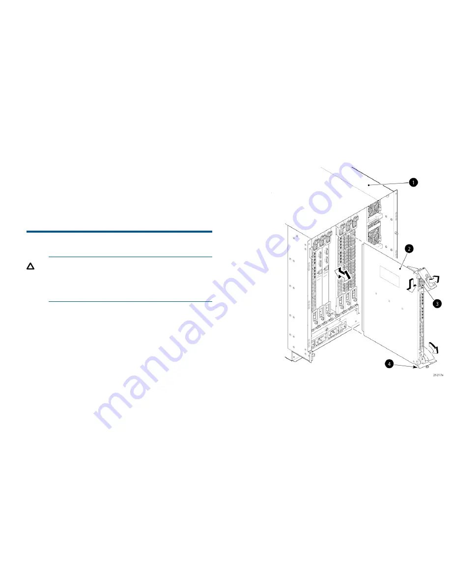
Figure 19 Removing and replacing a Director
blade with ejectors and slider switches
(FC4-16 shown)

2. FC4-16

1. 4/256 SAN Director
chassis

4. Ejectors (2)

3. On/Off slider switch

b.

Close the ejectors by pushing the handles
toward the center of the blade until the
ejectors lock.

The levering action of the handles seats the
blade in the slot.

c.

Tighten the thumb screw inside each handle
using the Phillips screwdriver.

d.

Turn the blade on by sliding up the slider
switch in the top ejector, covering the thumb
screw.

e.

Proceed to

Step 6

.

Page 12

Содержание SN8000B

Страница 1: ...Slot SAN Director Enhanced Fibre Channel Blade SN8000B 8 Slot SAN Backbone Director QK71 3A QK71 3B FC16 32 HP SN8000B 16Gb 32 port Fibre Channel Blade SN8000B 4 Slot SAN Director SN8000B 8 Slot SAN Backbone Director QK71 4A QK71 4B FC16 48 HP SN8000B 16Gb 48 port Fibre Channel Blade SN8000B 4 Slot SAN Director DC SAN Backbone nl AP866A AP866B FCOE10 24 HP DC SAN Director Switch 10 24 FCoE blade n...

Страница 2: ...B FC8 64 HP DC SAN Director nl 64 port 8Gb Fibre Channel Blade Director nl DC04 SAN Director nl SN8000B 8 Slot SAN Backbone Director SN8000B 4 Slot SAN Director 4 256 SAN Director DC SAN Backbone Director nl AK86 1A AK861B FC10 6 HP SAN Director nl 6 port 10Gb FC blade DC04 SAN Director 4 256 SAN Director AG67 1A AG671B FC4 16IP HP B series iSCSI nl Director blade 4 256 SAN Director nl AG46 1A AG4...

Страница 3: ...8 48E 2 Status LED 1 Power LED 4 FC ports 0 23 3 FC ports 24 47 FC16 32 components Figure 3 FC16 32 2 FC ports 8 15 1 Power LED 4 Port status LED 3 FC ports 0 7 6 Port and trunking group map 5 FC ports 24 31 7 FC ports 16 23 Page 3 ...

Страница 4: ...components Figure 4 FC16 48 2 FC ports 0 23 1 Power LED 4 FC ports 24 47 3 Status LED FCOE10 24 components Figure 5 FCOE10 24 2 10 GbE FCoE ports 0 1 1 1 Power LED 4 10 GbE FCoE ports 12 23 3 Status LED Page 4 ...

Страница 5: ...FX8 24 2 1 GbE ports 0 3 1 Power LED 4 FC ports 0 5 3 10 GbE ports 0 1 6 1 GbE ports 4 9 5 Status LED 7 FC ports 6 1 1 FS8 18 components Figure 7 FS8 18 2 Status LED 1 Power LED 4 Port status LED 3 FC port 5 FC ports 0 15 Page 5 ...

Страница 6: ...ed LED 3 FC Port 6 FC ports 0 15 5 Port status LED FC4 32 components Figure 9 FC4 32 2 Status LED 1 Power LED 4 Port speed LED left port 3 FC Port 6 Port speed LED right port 5 Port status LED left port 8 FC ports 16 31 7 Port status LED right port 9 FC ports 0 15 Page 6 ...

Страница 7: ...ts Figure 10 FC4 48 2 Status LED 1 Power LED 4 Port status LED 3 FC Port 6 FC ports 0 23 5 FC ports 24 47 FC8 16 components Figure 1 1 FC8 16 2 Status LED 1 Power LED 4 Port status LED 3 FC Port 5 FC ports 0 15 Page 7 ...

Страница 8: ...e 12 FC8 32 2 Status LED 1 Power LED 4 Port status LED 3 FC Port 6 FC ports 0 15 5 FC ports 16 31 FC8 48 components Figure 13 FC8 48 2 Status LED 1 Power LED 4 Port status LED 3 FC Port 6 FC ports 0 23 5 FC ports 24 47 Page 8 ...

Страница 9: ...D 1 Status LED 4 Port status LED 3 FC Port 6 FC Port 5 FC Port 8 FC ports 0 31 7 FC ports 32 63 NOTE FC8 64 supports mini SFPs mSFPs only FC10 6 components Figure 15 FC10 6 2 Status LED 1 Power LED 4 Port status LED 3 FC port 5 FC ports 0 5 Page 9 ...

Страница 10: ...6 FC4 16IP 2 Status LED 1 Power LED 4 Port status LED 3 FC Port 6 GbE ports 0 7 5 FC ports 0 7 FR4 18i components Figure 17 FR4 18i blade 2 Status LED 1 Power LED 4 Port status LED 3 FC Port 6 FC ports 0 15 5 GbE ports 0 1 Page 10 ...

Страница 11: ...Removing the filler panel Remove the filler panel if installed There are three filler panel types Figure 18 page 11 CAUTION Remove a filler panel only when installing or replacing a Director blade All slots that are not occupied by a Director blade require a filler panel to ensure cooling of the chassis and protection from dust To remove a filler panel with a handle 1 Unscrew the two captive screw...

Страница 12: ...or Install the blades in slots 1 through 4 and 9 through 12 For the HP SN8000B 4 Slot SAN Director Install the blades in slots 1 and 2 and slots 7 and 8 3 Orient the blade so that the ports face outward away from the slot and the flat noncomponent side is on the left 4 Proceed to Step 5 if the blade you are installing uses ejectors only See Determining the ejector type page 11 For blades with both...

Страница 13: ...7 Install the transceivers and cables For more information This document provides initial setup and configuration procedures only For comprehensive configuration procedures including those for mixed blade configurations see the following HP B series SN8000B 8 Slot SAN Backbone Director Switch Hardware Reference Guide HP HP B series SN8000B 4 Slot SAN Director Switch Hardware Reference Guide HP Sto...

Отзывы: