


3.
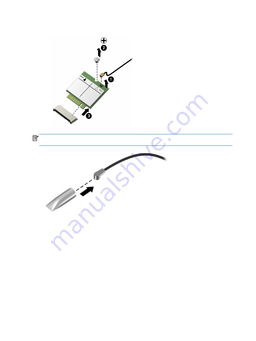
Remove the WLAN module
(3)
by pulling the module away from the slot at an angle.
NOTE:
If the WLAN antenna cable is not connected to the terminal on the WLAN module, a
protective sleeve should be installed on the antenna connector, as shown in the following illustration.
Reverse this procedure to install the WLAN module.
24
Chapter 4 Removal and replacement procedures
Содержание SlateBook PC
Страница 4: ...iv Safety warning notice ...
Страница 10: ...Computer major components 4 Chapter 2 Illustrated parts catalog ...


