HP ProLiant ML110 Gen9 Скачать руководство пользователя страница 66


Removal and replacement procedures  66 

2.


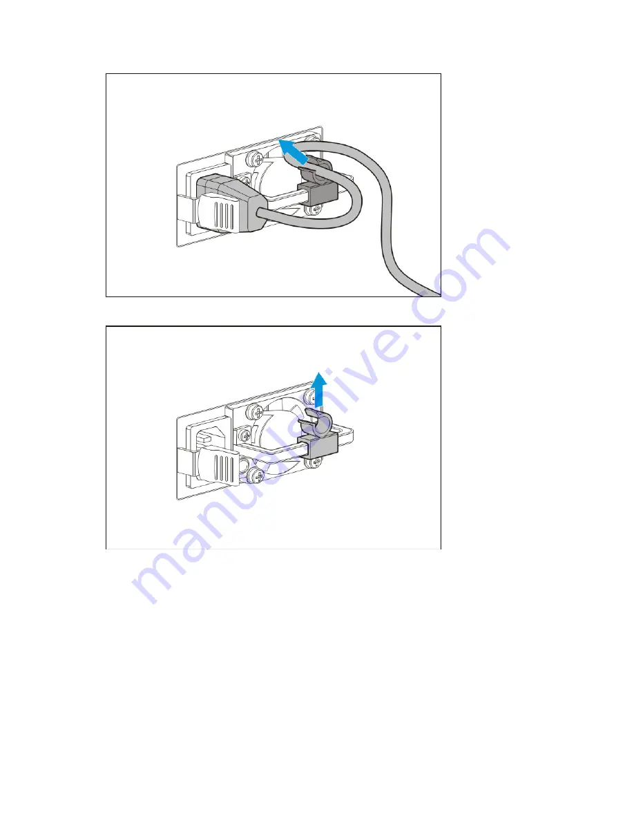
Release the power cord from the strain relief clip. 


3.


Remove the strain relief clip from RPS and retain the clip for future use. 


4.


Remove all power: 

a.


Disconnect each power cord from the power source. 

b.


Disconnect each power cord from the server. 

5.


Place the server on a sturdy, level surface. 

6.


Remove the access panel (on page 

25

). 

7.


If installed, remove the PCI air baffle (on page 

27

). 

8.


Remove the system air baffle (on page 

28

). 

9.


Disconnect all power supply cables from the system board, drive cages, and devices. 

Содержание ProLiant ML110 Gen9

Страница 1: ...c tools specifications and requirements for hardware components and software This guide is for an experienced service technician HP assumes that you are qualified in the servicing of computer equipment trained in recognizing hazards in products and are familiar with weight and stability precautions Part Number 790389 001 March 2015 Edition 1 ...

Страница 2: ... products and services Nothing herein should be construed as constituting an additional warranty HP shall not be liable for technical or editorial errors or omissions contained herein Linux is the registered trademark of Linus Torvalds in the U S and other countries Microsoft and Windows are trademarks of the Microsoft group of companies microSD is a trademark or a registered trademark of SD 3C in...

Страница 3: ...ot plug drive cage 28 Non hot plug drive 29 Hot plug drive blanks 30 Hot plug drive 31 4 bay LFF hot plug drive cage 32 8 bay SFF hot plug drive cage 33 Optical drive 34 Fans 36 System fan module 92 x 32 mm 36 Upgrade fan module 92 x 38 mm 37 PCI fan module 38 GPU supporting holder 39 FBWC module 41 HP Smart Storage Battery 42 DIMMs 43 Heatsink 44 Processor 46 System board 51 System battery 58 Ded...

Страница 4: ...7 Front panel LEDs and buttons 78 Front panel LED power fault codes 78 Rear panel components 79 Rear panel LEDs 80 System board components 81 System maintenance switch 82 NMI functionality 83 DIMM slot locations 83 Fan locations 84 Drive numbering 84 HP SmartDrive LED definitions 86 Cabling 88 Cabling overview 88 Storage cabling 88 4 bay LFF non hot plug drive cabling 88 4 bay LFF hot plug drive c...

Страница 5: ...Contents 5 Power supply specifications 103 Hot plug power supply calculations 103 Acronyms and abbreviations 104 Documentation feedback 107 Index 108 ...

Страница 6: ...n will help you over the telephone HP specifies in the materials shipped with a replacement CSR part whether a defective part must be returned to HP In cases where it is required to return the defective part to HP you must ship the defective part back to HP within a defined period of time normally five 5 business days The defective part must be returned with the associated documentation in the pro...

Страница 7: ...ine la société de courses ou le transporteur à utiliser Pour plus d informations sur le programme CSR de HP contactez votre Mainteneur Agrée local Pour plus d informations sur ce programme en Amérique du Nord consultez le site Web HP http www hp com go selfrepair Service de garantie pièces seules Votre garantie limitée HP peut inclure un service de garantie pièces seules Dans ce cas les pièces de ...

Страница 8: ... Self Repair um Reparaturzeiten zu minimieren und höhere Flexibilität beim Austausch defekter Bauteile zu ermöglichen Wenn HP oder ein HP Servicepartner bei der Diagnose feststellt dass das Produkt mithilfe eines CSR Teils repariert werden kann sendet Ihnen HP dieses Bauteil zum Austausch direkt zu CSR Teile werden in zwei Kategorien unterteilt Zwingend Teile für die das Customer Self Repair Verfa...

Страница 9: ...tegorías Obligatorio componentes para los que la reparación por parte del usuario es obligatoria Si solicita a HP que realice la sustitución de estos componentes tendrá que hacerse cargo de los gastos de desplazamiento y de mano de obra de dicho servicio Opcional componentes para los que la reparación por parte del usuario es opcional Estos componentes también están diseñados para que puedan ser r...

Страница 10: ...gorieën CSR onderdelen Verplicht Onderdelen waarvoor reparatie door de klant verplicht is Als u HP verzoekt deze onderdelen voor u te vervangen worden u voor deze service reiskosten en arbeidsloon in rekening gebracht Optioneel Onderdelen waarvoor reparatie door de klant optioneel is Ook deze onderdelen zijn ontworpen voor reparatie door de klant Als u echter HP verzoekt deze onderdelen voor u te ...

Страница 11: ...ependendo do tipo de serviço de garantia destinado ao produto OBSERVAÇÃO Algumas peças da HP não são projetadas para o reparo feito pelo cliente A fim de cumprir a garantia do cliente a HP exige que um técnico autorizado substitua a peça Essas peças estão identificadas com a marca No Não no catálogo de peças ilustrado Conforme a disponibilidade e o local geográfico as peças CSR serão enviadas no p...

Страница 12: ...Customer self repair 12 No caso desse serviço a substituição de peças CSR é obrigatória Se desejar que a HP substitua essas peças serão cobradas as despesas de transporte e mão de obra do serviço ...

Страница 13: ...Customer self repair 13 ...

Страница 14: ...Customer self repair 14 ...

Страница 15: ...Customer self repair 15 ...

Страница 16: ...1 Mandatory1 6 PCI air baffle 791709 001 Mandatory1 1 Mandatory Parts for which customer self repair is mandatory If you request HP to replace these parts you will be charged for the travel and labor costs of this service 2 Optional Parts for which customer self repair is optional These parts are also designed for customer self repair If however you require that HP replace them for you there may o...

Страница 17: ...rvicepartner ersetzt werden Im illustrierten Teilekatalog sind diese Teile mit No bzw Nein gekennzeichnet 1 Mandatory Obligatorio componentes para los que la reparación por parte del usuario es obligatoria Si solicita a HP que realice la sustitución de estos componentes tendrá que hacerse cargo de los gastos de desplazamiento y de mano de obra de dicho servicio 2 Optional Opcional componentes para...

Страница 18: ...Illustrated parts catalog 18 ...

Страница 19: ...1 Mandatory1 11 HP ATX 550 W Power Supply non hot plug 791706 001 Mandatory1 12 HP 750 W Common Slot Gold Hot Plug Power Supply 511778 001 Mandatory1 13 RPS enablement kit 791712 001 Optional2 14 4 bay LFF hot plug drive cage 792351 001 Optional2 15 8 bay SFF hot plug drive cage 792352 001 Optional2 16 PCI fan module 791710 001 Mandatory1 17 HP Smart Storage Battery 750450 001 Mandatory1 18 Dedica...

Страница 20: ...h customer self repair is mandatory If you request HP to replace these parts you will be charged for the travel and labor costs of this service 2 Optional Parts for which customer self repair is optional These parts are also designed for customer self repair If however you require that HP replace them for you there may or may not be additional charges depending on the type of warranty service desi...

Страница 21: ...r parte del usuario es opcional Estos componentes también están diseñados para que puedan ser reparados por el usuario Sin embargo si precisa que HP realice su sustitución puede o no conllevar costes adicionales dependiendo del tipo de servicio de garantía correspondiente al producto 3 No No Algunos componentes no están diseñados para que puedan ser reparados por el usuario Para que el usuario hag...

Страница 22: ...Illustrated parts catalog 22 ...

Страница 23: ...s in static safe containers Keep electrostatic sensitive parts in their containers until they arrive at static free workstations Place parts on a grounded surface before removing them from their containers Avoid touching pins leads or circuitry Always be properly grounded when touching a static sensitive component or assembly Symbols on equipment The following symbols may be placed on equipment to...

Страница 24: ...or manual material handling Get help to lift and stabilize the product during installation or removal especially when the product is not fastened to the rails HP recommends that a minimum of two people are required for all rack server installations A third person may be required to help align the server if the server is installed higher than chest level Use caution when installing the server in or...

Страница 25: ...e than 4 seconds to force the server to enter standby mode This method forces the server to enter standby mode without properly exiting applications and the OS If an application stops responding you can use this method to force a shutdown Use a virtual power button selection through iLO 4 This method initiates a controlled remote shutdown of applications and the OS before the server enters standby...

Страница 26: ...side 4 Remove the access panel a Loosen the access panel thumbscrews b Slide and remove the access panel from the server Remove the front bezel 1 Power down the server on page 25 2 Remove all power a Disconnect each power cord from the power source b Disconnect each power cord from the server 3 Place the server on its side 4 Remove the access panel on page 25 ...

Страница 27: ... the front bezel Remove the PCI air baffle 1 Power down the server on page 25 2 Remove all power a Disconnect each power cord from the power source b Disconnect each power cord from the server 3 Place the server on its side 4 Remove the access panel on page 25 5 Remove the PCI air baffle ...

Страница 28: ...ot plug drive cage CAUTION To prevent improper cooling and thermal damage do not operate the server unless all bays are populated with either a component or a blank To remove the component 1 Back up all server data on the drive 2 Power down the server on page 25 3 Remove all power a Disconnect each power cord from the power source b Disconnect each power cord from the server 4 Place the server on ...

Страница 29: ... blank To remove the component 1 Back up all server data on the drive 2 Power down the server on page 25 3 Remove all power a Disconnect each power cord from the power source b Disconnect each power cord from the server 4 Place the server on its side 5 Remove the access panel on page 25 6 Remove the front bezel on page 26 7 If installed remove the PCI air baffle on page 27 8 Remove the system air ...

Страница 30: ...lanks CAUTION To prevent improper cooling and thermal damage do not operate the server unless all bays are populated with either a component or a blank To remove the component 1 Remove the front bezel on page 26 2 Remove the drive blank o Hot plug LFF drive blank To replace the LFF drive blank slide the component into the bay until it clicks ...

Страница 31: ...nt improper cooling and thermal damage do not operate the server unless all bays are populated with either a component or a blank To remove the component 1 Back up all server data on the drive 2 Remove the front bezel on page 26 3 Determine the status of the drive from the drive LED definitions HP SmartDrive LED definitions on page 86 4 Remove the hot plug drive To replace the component reverse th...

Страница 32: ...m the server 3 Place the server on its side 4 Remove the access panel on page 25 5 Remove the front bezel on page 26 6 Remove all drives Hot plug drive on page 31 7 Remove all drive blanks Hot plug drive blanks on page 30 8 If installed remove the PCI air baffle on page 27 9 Remove the system air baffle on page 28 10 Disconnect the Mini SAS cable and the power cable from the drive backplane 11 Dis...

Страница 33: ...ce b Disconnect each power cord from the server 3 Place the server on its side 4 Remove the access panel on page 25 5 Remove the front bezel on page 26 6 Remove all drives Hot plug drive on page 31 7 Remove all drive blanks Hot plug drive blanks on page 30 8 If installed remove the PCI air baffle on page 27 9 Remove the system air baffle on page 28 10 Disconnect the Mini SAS cable and the power ca...

Страница 34: ...verse the removal procedure Optical drive To remove the component 1 Power down the server on page 25 2 Remove all power a Disconnect each power cord from the power source b Disconnect each power cord from the server 3 Place the server on its side 4 Remove the access panel on page 25 ...

Страница 35: ... 35 5 Remove the front bezel on page 26 6 If installed remove the PCI air baffle on page 27 7 Remove the system air baffle on page 28 8 Disconnect the power and SATA cable 9 Release cables from clip and metal tabs 10 Press the metal tab ...

Страница 36: ...re Fans System fan module 92 x 32 mm To remove the component 1 Power down the server on page 25 2 Remove all power a Disconnect each power cord from the power source b Disconnect each power cord from the server 3 Place the server on its side 4 Remove the access panel on page 25 5 If installed remove the PCI air baffle on page 27 6 Remove the system air baffle on page 28 ...

Страница 37: ...ule 92 x 38 mm To remove the component 1 Power down the server on page 25 2 Remove all power a Disconnect each power cord from the power source b Disconnect each power cord from the server 3 Place the server on its side 4 Remove the access panel on page 25 5 If installed remove the PCI air baffle on page 27 6 Remove the system air baffle on page 28 ...

Страница 38: ...t reverse the removal procedure PCI fan module CAUTION For proper cooling do not operate the server without the access panel baffles expansion slot covers or blanks installed To remove the component 1 Power down the server on page 25 2 Remove all power a Disconnect each power cord from the power source b Disconnect each power cord from the server ...

Страница 39: ...and remove the PCI fan To replace the component reverse the removal procedure GPU supporting holder To remove the component 1 Power down the server on page 25 2 Remove all power a Disconnect each power cord from the power source b Disconnect each power cord from the server 3 Place the server on its side 4 Remove the access panel on page 25 5 If installed remove the PCI air baffle on page 27 6 Remo...

Страница 40: ... Disconnect the 6 pin power cable from the GPU 8 Remove the GPU with the supporting holder from slot 1 a Open the PCIe slot cover retainer b Loosen the captive screw of the supporting holder c Open the latch on the slot 1 and remove the GPU ...

Страница 41: ...ION To prevent damage to electrical components take the appropriate anti static precautions before beginning any installation removal or replacement procedure Improper grounding can cause electrostatic discharge To remove the component 1 Power down the server on page 25 2 Remove all power a Disconnect each power cord from the power source b Disconnect each power cord from the server 3 Place the se...

Страница 42: ...e backup power cable from the cache module 10 Remove the cache module To replace the component reverse the removal procedure HP Smart Storage Battery WARNING To reduce the risk of personal injury from hot surfaces allow the drives and the internal system components to cool before touching them CAUTION To prevent damage to electrical components take the appropriate anti static precautions before be...

Страница 43: ...m air baffle on page 28 7 Disconnect the battery cable from the system board connector and remove the HP Smart Storage Battery To replace the component reverse the removal procedure DIMMs To remove the component 1 Power down the server on page 25 2 Remove all power a Disconnect each power cord from the power source b Disconnect each power cord from the server 3 Place the server on its side 4 Remov...

Страница 44: ...ach power cord from the power source b Disconnect each power cord from the server 3 Place the server on its side 4 Remove the access panel on page 25 5 If installed remove the PCI air baffle on page 27 6 Remove the system air baffle on page 28 7 Remove the heatsink a Loosen one pair of diagonally opposite screws halfway and then loosen the other pair of screws b Completely loosen all screws in the...

Страница 45: ...l grease from the processor with the alcohol swab Allow the alcohol to evaporate before continuing 2 Remove the thermal interface protective cover from the heatsink 3 Install the heatsink a Position the heatsink on the processor backplate b Tighten one pair of diagonally opposite screws halfway and then tighten the other pair of screws ...

Страница 46: ...hing them CAUTION To avoid damage to the processor and system board only authorized personnel should attempt to replace or install the processor in this server CAUTION To prevent possible server malfunction and damage to the equipment multiprocessor configurations must contain processors with the same part number CAUTION To prevent damage to electrical components take the appropriate anti static p...

Страница 47: ...ed remove the PCI air baffle on page 27 6 Remove the system air baffle on page 28 7 Remove the heatsink a Loosen one pair of diagonally opposite screws halfway and then loosen the other pair of screws b Completely loosen all screws in the same sequence c Remove the heatsink from the processor backplate 8 Open each of the processor locking levers in the order indicated and then open the processor r...

Страница 48: ...es 48 CAUTION THE PINS ON THE SYSTEM BOARD ARE VERY FRAGILE AND EASILY DAMAGED To avoid damage to the system board do not touch the processor or the processor socket contacts 9 Remove the processor from the processor retaining bracket ...

Страница 49: ...YSTEM BOARD ARE VERY FRAGILE AND EASILY DAMAGED To avoid damage to the system board do not touch the processor or the processor socket contacts CAUTION Do not press down on the processor Pressing down on the processor may cause damage to the processor socket and the system board Press only in the area indicated on the processor retaining bracket 2 Close the processor retaining bracket When the pro...

Страница 50: ...racket 4 Clean the old thermal grease from the heatsink with the alcohol swab Allow the alcohol to evaporate before continuing 5 Apply all the grease to the top of the processor in the following pattern to ensure even distribution 6 Install the heatsink a Position the heatsink on the processor backplate b Tighten one pair of diagonally opposite screws halfway and then tighten the other pair of scr...

Страница 51: ...1 Power down the server on page 25 2 Remove all power a Disconnect each power cord from the power source b Disconnect each power cord from the server 3 Place the server on its side 4 Remove the access panel on page 25 5 If installed remove the PCI air baffle on page 27 6 Remove the system air baffle on page 28 7 Remove all DIMMs DIMMs on page 43 8 If installed remove the dedicated iLO module Dedic...

Страница 52: ...screws in the same sequence c Remove the heatsink from the processor backplate 13 Open each of the processor locking levers in the order indicated and then open the processor retaining bracket CAUTION THE PINS ON THE SYSTEM BOARD ARE VERY FRAGILE AND EASILY DAMAGED To avoid damage to the system board do not touch the processor or the processor socket contacts ...

Страница 53: ...er removing the processor from the socket Do not tilt or slide the processor when lowering the processor into the socket CAUTION Removal of the processor or heatsink renders the thermal layer between the processor and heatsink useless Clean the component with the provided alcohol swab then add thermal grease 15 Place the processor on a static dissipating work surface or inside an anti static bag 1...

Страница 54: ...cement procedures 54 To replace the system board 1 Install the system board 2 Open each of the processor locking levers in the order indicated in the following illustration and then open the processor retaining bracket ...

Страница 55: ...ocessor socket contacts 4 Install the processor Verify that the processor is fully seated in the processor retaining bracket by visually inspecting the processor installation guides on either side of the processor THE PINS ON THE SYSTEM BOARD ARE VERY FRAGILE AND EASILY DAMAGED 5 Close the processor retaining bracket When the processor is installed properly inside the processor retaining bracket t...

Страница 56: ...e without resistance Forcing the levers closed can damage the processor and socket requiring system board replacement 6 Press and hold the processor retaining bracket in place and then close each processor locking lever Press only in the area indicated on the processor retaining bracket 7 Clean the old thermal grease from the heatsink and the top of the processor with the alcohol swab Allow the al...

Страница 57: ...cess panel 15 Return the server to an upright position 16 Connect each power cord to the server 17 Connect each power cord to the power source 18 Power up the server IMPORTANT Install all components with the same configuration that was used on the failed system board After you replace the system board you must re enter the server serial number and the product ID 1 During the server startup sequenc...

Страница 58: ...anadium pentoxide or an alkaline battery pack A risk of fire and burns exists if the battery pack is not properly handled To reduce the risk of personal injury Do not attempt to recharge the battery Do not expose the battery to temperatures higher than 60 C 140 F Do not disassemble crush puncture short external contacts or dispose of in fire or water Replace only with the spare designated for this...

Страница 59: ...mation about battery replacement or proper disposal contact an authorized reseller or an authorized service provider Dedicated iLO port management module To remove the component 1 Power down the server on page 25 2 Remove all power a Disconnect each power cord from the power source b Disconnect each power cord from the server 3 Place the server on its side 4 Remove the access panel on page 25 5 If...

Страница 60: ... com go ProLiantUEFI docs IMPORTANT If the iLO configuration settings are reset to the default values remote access to the machine will be lost Access the physical machine and repeat the procedure described in this section to re enable the dedicated iLO management connector To enable the dedicated iLO management module 1 During the server startup sequence after installing the module press F9 in th...

Страница 61: ... components take the appropriate anti static precautions before beginning any installation removal or replacement procedure Improper grounding can cause electrostatic discharge To remove the component 1 Power down the server on page 25 2 Remove all power a Disconnect each power cord from the power source b Disconnect each power cord from the server 3 Place the server on its side 4 Remove the acces...

Страница 62: ... can cause electrostatic discharge To remove the component 1 Power down the server on page 25 2 Remove all power a Disconnect each power cord from the power source b Disconnect each power cord from the server 3 Place the server on its side 4 Remove the access panel on page 25 5 If installed remove the PCI air baffle on page 27 6 Remove the system air baffle on page 28 7 Disconnect all power supply...

Страница 63: ... the cord extends from the equipment WARNING To reduce the risk of injury from electric shock hazards do not open power supplies Refer all maintenance upgrades and servicing to qualified personnel WARNING To reduce the risk of personal injury from hot surfaces allow the drives and the internal system components to cool before touching them CAUTION To prevent damage to electrical components properl...

Страница 64: ...source b Disconnect each power cord from the server 5 Place the server on a sturdy level surface 6 Remove the access panel on page 25 7 If installed remove the PCI air baffle on page 27 8 Remove the system air baffle on page 28 9 Disconnect all power supply cables from the system board drive cages and devices 10 Remove the hot plug power input module 11 Remove the RPS backplane ...

Страница 65: ... placed against it Pay particular attention to the plug electrical outlet and the point where the cord extends from the equipment WARNING To reduce the risk of injury from electric shock hazards do not open power supplies Refer all maintenance upgrades and servicing to qualified personnel WARNING To reduce the risk of personal injury from hot surfaces allow the drives and the internal system compo...

Страница 66: ...Remove all power a Disconnect each power cord from the power source b Disconnect each power cord from the server 5 Place the server on a sturdy level surface 6 Remove the access panel on page 25 7 If installed remove the PCI air baffle on page 27 8 Remove the system air baffle on page 28 9 Disconnect all power supply cables from the system board drive cages and devices ...

Страница 67: ...N To prevent improper cooling and thermal damage do not operate the server unless all bays are populated with either a component or a blank To remove the component 1 Power down the server on page 25 2 Access the product rear panel WARNING To reduce the risk of personal injury from hot surfaces allow the power supply or power supply blank to cool before touching it 3 Remove the power supply blank ...

Страница 68: ...ystem board breaks or disfigures the TPM security rivet Upon locating a broken or disfigured rivet on an installed TPM administrators should consider the system compromised and take appropriate measures to ensure the integrity of the system data If you suspect a TPM board failure leave the TPM installed and remove the system board Contact an HP authorized service provider for a replacement system ...

Страница 69: ...ort Gen9_TSG_es German http www hp com support Gen9_TSG_de Japanese http www hp com support Gen9_TSG_ja Simplified Chinese http www hp com support Gen9_TSG_zh_cn The HP ProLiant Gen9 Troubleshooting Guide Volume II Error Messages provides a list of error messages and information to assist with interpreting and resolving error messages on ProLiant servers and server blades To view the guide select ...

Страница 70: ...the following Access a high performance and secure Integrated Remote Console to the server from anywhere in the world if you have a network connection to the server Use the shared NET Integrated Remote Console to collaborate with up to four server administrators Remotely mount high performance Virtual Media devices to the server Securely and remotely control the power state of the managed server I...

Страница 71: ...data that is collected is managed according to the HP Data Privacy policy For more information see the HP website http www hp com go privacy The Active Health System in conjunction with the system monitoring provided by Agentless Management or SNMP Pass thru provides continuous monitoring of hardware and configuration changes system status and service alerts for various server components The Agent...

Страница 72: ...age 74 HP UEFI System Utilities The HP UEFI System Utilities is embedded in the system ROM The UEFI System Utilities enable you to perform a wide range of configuration activities including Configuring system devices and installed options Enabling and disabling system features Displaying system information Selecting the primary boot controller Configuring memory options Selecting a language Launch...

Страница 73: ... see the HP UEFI System Utilities User Guide for HP ProLiant Gen9 Servers on the HP website http www hp com go ProLiantUEFI docs Re entering the server serial number and product ID After you replace the system board you must re enter the server serial number and the product ID 1 During the server startup sequence press the F9 key to access UEFI System Utilities 2 Select the System Configuration BI...

Страница 74: ...iles to reflect the latest changes in the configuration Survey functionality is installed with every Intelligent Provisioning assisted HP Insight Diagnostics installation or it can be installed through the SPP HP Insight Remote Support HP strongly recommends that you register your device for remote support to enable enhanced delivery of your HP Warranty HP Care Pack Service or HP contractual suppo...

Страница 75: ...e USB 3 0 ports cannot function in the pre boot environment and are not bootable Disabled If configured for Disabled USB 3 0 capable devices function at USB 2 0 speeds at all times The pre OS behavior of the USB ports is configurable in System Utilities so that the user can change the default operation of the USB ports For more information see the HP UEFI System Utilities User Guide for HP ProLian...

Страница 76: ...nown as the Health Driver is loaded When the operating system is functioning properly the system periodically resets the timer However when the operating system fails the timer expires and restarts the server ASR increases server availability by restarting the server within a specified time after a system hang At the same time the HP SIM console notifies you by sending a message to a designated pa...

Страница 77: ...Component identification 77 Component identification Front panel components Item Description 1 Optical drive optional 2 Box 2 3 Box 1 4 USB 3 0 connectors ...

Страница 78: ... panel flash simultaneously a power fault has occurred For more information see Front panel LED power fault codes on page 78 For the location of the UID button LED on the rear panel see Rear panel LEDs on page 80 Facility power is not present power cord is not attached no power supplies are installed power supply failure has occurred or the power button cable is disconnected If the health LED indi...

Страница 79: ...e Front panel LEDs and buttons on page 78 Rear panel components Item Description 1 Non hot plug power supply 2 Power supply bay 1 of the hot plug power supply optional 3 Power supply bay 2 of the hot plug power supply optional 4 NIC connector 1 5 NIC connector 2 6 Dedicated iLO port optional 7 Slot 5 PCIe3x8 8 4 1 8 Slot 4 PCIe3x4 4 1 9 Slot 3 PCIe3x8 8 4 1 10 Slot 2 PCIe3x4 4 1 11 Slot 1 PCIe3x16...

Страница 80: ...work connection 3 iLO activity LED Green or flashing green Network activity Off No network activity 4 NIC activity LED Green or flashing green Network activity Off No network activity 5 NIC link LED Green Linked to network Off No network connection 6 UID button LED Solid blue Activated Flashing blue 1 Hz cycle per sec Remote management or firmware upgrade in progress 4 Hz cycle per sec iLO manual ...

Страница 81: ...5 RPSU connector 6 Processor 7 4 pin power supply connector 8 Front I O connector 9 Fan connector 1 10 Mini SAS connector 1 11 Front USB 3 0 connector 12 SATA connector 2 13 Mini SAS connector 2 14 SATA connector 1 15 Internal USB 3 0 connector 16 Internal USB 2 0 connector 17 Storage backup power connector 18 Hard drive power good cable connector 2 ...

Страница 82: ...iguration can be changed On System configuration is locked S3 Off Reserved S4 Off Reserved S5 Off Off Power on password is enabled On Power on password is disabled S6 Off Off No function On ROM reads system configuration as invalid S7 Off Off Set default boot mode to UEFI On Set default boot mode to legacy S8 Reserved S9 Reserved S10 Reserved S11 Reserved S12 Reserved To access the redundant ROM s...

Страница 83: ... system and the only available action for administrators is to restart the system Resetting the system erases any information which could support problem analysis but the NMI feature preserves that information by performing a memory dump before a system reset To force the system to invoke the NMI handler and generate a crash dump log do one of the following Use the iLO Virtual NMI feature Short th...

Страница 84: ...umbering for each of the supported drive configurations For drive box numbering information see Front panel components on page 77 With optional drive cages installed the server supports up to 4 LFF non hot plug drives 8 LFF hot plug drives or 16 SFF hot plug drives If only one drive cage is installed it must be installed in box 1 The server does not support mixing SFF and LFF drives HP recommends ...

Страница 85: ...Component identification 85 Four bay LFF non hot plug drive model Four bay LFF hot plug drive model ...

Страница 86: ...art of an array and connected to a powered up controller the drive LEDs indicate the condition of the drive Item LED Status Definition 1 Locate Solid blue The drive is being identified by a host application Flashing blue The drive carrier firmware is being updated or requires an update 2 Activity ring Rotating green Drive activity Off No drive activity 3 Do not remove Solid white Do not remove the...

Страница 87: ...nd is visible when illuminated IMPORTANT The HP Dynamic Smart Array B140i Controller is only available in UEFI Boot Mode It cannot be enabled in Legacy BIOS Boot Mode If the B140i controller is disabled drives connected to the system board Mini SAS connectors operate in AHCI or Legacy mode Under this condition The drives cannot be a part of a hardware RAID or a logical drive The Locate Drive statu...

Страница 88: ...abling peripheral components refer to the white paper on high density deployment at the HP website http www hp com products servers platforms CAUTION When routing cables always be sure that the cables are not in a position where they can be pinched or crimped Storage cabling 4 bay LFF non hot plug drive cabling Box 1 Item Description 1 Power supply cable 2 Box 1 drive power cable 3 Mini SAS cable ...

Страница 89: ... backplane connected to the system board Item Description 1 Drive power cable 2 Mini SAS cable 3 Hard drive power good cable Box 2 drive backplane connected the system board Item Description 1 Drive power cable 2 Mini SAS cable 3 Hard drive power good cable ...

Страница 90: ...cable 3 Mini SAS cable to port 2 of the controller 4 Mini SAS cable to port 1of the controller 5 Box 1 hard drive power good cable 6 Box 2 hard drive power good cable Box 1 and box 2 drive backplanes connected to a P440 controller Item Description 1 Box 2 drive power cable 2 Box 1 drive power cable 3 Mini SAS Y cable to the controller ...

Страница 91: ...rd drive power good cable Box 1 and box 2 drive backplane connected to a P840 controller Item Description 1 Box 2 drive power cable 2 Box 1 drive power cable 3 Mini SAS Y cable to port 1 of the controller 4 Box 2 hard drive power good cable 5 Box 1 hard drive power good cable ...

Страница 92: ...scription 1 Drive power cable 2 Mini SAS port 1 connection 3 Mini SAS port 2 connection 4 Hard drive power good cable Box 1 drive backplane connected to an H240 adapter Item Description 1 Drive power cable 2 Mini SAS port 1 connection to port 1 controller 3 Mini SAS port 2 connection to port 2 controller ...

Страница 93: ...40 adapter Item Description 1 Drive power cable 2 Mini SAS port 1 connection to port 1 controller 3 Mini SAS port 2 connection to port 2 controller 4 Hard drive power good cable Box 1 drive backplane connected to a P440 controller Item Description 1 Drive power cable 2 Mini SAS Y cable to controller ...

Страница 94: ...to a P440 controller Item Description 1 Drive power cable 2 Mini SAS Y cable to controller 3 Hard drive power good cable Box 1 drive backplane connected to a P840 controller Item Description 1 Drive power cable 2 Mini SAS Y cable connection to port 1 controller 3 Hard drive power good cable ...

Страница 95: ...ower good cable FBWC module cabling The FBWC solution is a separately purchased option This server only supports FBWC module installation when an HP Smart Array P Series controller is installed Depending on the controller option installed the actual storage controller connectors might look different from what is shown in this section FBWC module on a P440 controller ...

Страница 96: ...Cabling 96 FBWC module on a P840 controller HP Smart Storage Battery cabling ...

Страница 97: ...Cabling 97 Optical drive cabling Item Description 1 Power supply cable 2 Drive power cable 3 SATA cable Fan cabling Default system fan 92 x 32 mm ...

Страница 98: ...Cabling 98 Optional system upgrade fan 92 x 38 mm PCI fan ...

Страница 99: ...ly non hot plug Item Description 1 8 pin power supply cable to box 2 drive backplane and optical drive 2 8 pin power supply cable to box 1 drive backplane 3 4 pin power cable to system board 4 24 pin power supply cable HP ATX 550 W power supply non hot plug ...

Страница 100: ...ane 4 4 pin power cable to system board 5 24 pin power cable to system board HP 750 W redundant power supply Item Description 1 8 pin power supply cable to box 2 drive backplane and optical drive 2 8 pin power supply cable to box 1 drive backplane 3 6 pin power cable to GPU 4 4 pin power cable to system board 5 RPS cable to system board 6 24 pin power cable to system board ...

Страница 101: ...Cabling 101 Front I O cabling Front USB 3 0 cabling ...

Страница 102: ...change might be limited by the type and number of options installed For certain approved hardware configurations the supported system inlet temperature range is extended 5 C to 10 C 41 F to 50 F and 35 C to 40 C 95 F to 104 F at sea level with an altitude derating of 1 0 C per every 175 m 1 8 F per every 574 ft above 900 m 2953 ft to a maximum of 3048 m 10 000 ft 40 C to 45 C 104 F to 113 F at sea...

Страница 103: ...t Plug Power Supply 512327 B21 This is supported when the two bay HP RPS Enablement option PN 784582 B21 is installed These are Entry Level Power Supply products for HP ProLiant servers For more information about the power supply features specifications and compatibility see the HP website http www hp com go proliant powersupply CAUTION Check the system and power supply input ratings before poweri...

Страница 104: ...rface ASHRAE American Society of Heating Refrigerating and Air Conditioning Engineers BP backplane CSR Customer Self Repair FAT file allocation table FBWC flash backed write cache GPU graphics processing unit HBA host bus adapter HP SIM HP Systems Insight Manager iLO Integrated Lights Out IML Integrated Management Log ...

Страница 105: ...errupt NVRAM nonvolatile memory ODD Optical Disk Drive PCIe Peripheral Component Interconnect Express POST Power On Self Test RBSU ROM Based Setup Utility REST representational state transfer RPS redundant power supply SAS serial attached SCSI SATA serial ATA SD Secure Digital SFF small form factor ...

Страница 106: ...yms and abbreviations 106 SIM Systems Insight Manager SPP HP Service Pack for ProLiant TPM Trusted Platform Module UEFI Unified Extensible Firmware Interface UID unit identification USB universal serial bus ...

Страница 107: ...oviding documentation that meets your needs To help us improve the documentation send any errors suggestions or comments to Documentation Feedback mailto docsfeedback hp com Include the document title and part number version number or the URL when submitting your feedback ...

Страница 108: ...s system board 81 crash dump analysis 83 customer self repair CSR 6 D dedicated iLO management module 59 diagnosing problems 69 diagnostic tools 70 73 74 76 dimensions and weight 102 DIMM slot locations 83 DIMMs removing 43 documentation feedback 107 drive blank 30 31 drive cabling 88 drive carrier 28 drive LEDs 86 drive numbering 84 drives determining status of 86 E electrostatic discharge 23 emb...

Страница 109: ...on UID 78 legacy USB support 74 M management tools 70 mechanical components 16 memory dump 83 microSD card slot 81 Mini SAS cabling 88 89 92 N NIC activity LED 78 NIC connectors 77 NIC link LED 78 NMI functionality 83 NMI header 83 non hot plug drive carrier 28 non hot plug drives 29 non hot plug power supply 61 103 O operating system crash 76 83 operating systems supported 74 optical drive 34 77 ...

Страница 110: ...plug 88 symbols on equipment 23 system air baffle 28 system board 51 system board battery 96 system board components 81 system components 19 system configuration settings 82 system fan 36 system maintenance switch 82 T T 10 T 15 Torx screwdriver 23 technical support 6 temperature requirements 102 tools 23 TPM connector 81 troubleshooting resources 69 Trusted Platform Module TPM 68 U UEFI System Ut...

Отзывы: