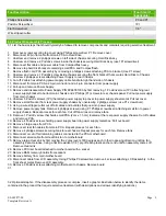
EL-MF877-00 Page 2
Template Revision A
Tool Description
Tool Size (if
applicable)
Phillips Screwdriver
P0 and P1
Pozidriv Screwdriver
1Pt
Flat Screwdriver
1/8"
Wire stripper/cutter
3.0 Product Disassembly Process
3.1 List the basic steps that should typically be followed to remove components and materials requiring selective treatment:
1. Remove screws securing top cover using Phillips screw driver P1. Remove cover
2. Disconnect 40 pin flat cable from main PCA to Hard Drive
3. Unscrew and remove 2 philipps screws on left side of chassis securing Hard Disk Assy
4. Unscrew and remove 2 Pozidriv screws inside the chassis securing Hard Disk Assy (use 1Pt screwdriver)
5. Disconnect flat cable and power cable from Compactflash assy.
6. Remove top hard disk bracket containing small PCA and Compactflash .
7. Remove flash card PCA assembly by removing 4 philipps screws attaching PCA to bracket (Use P1 screw)
8. Unscrew and remove 1 Pozidriv screw inside chassis securing the front bracket that secures Hard Disk to Chassis
9. Unscrew 2 philipps screws attaching Power Supply to rear Chassis
10. Cut off 2 cable ties attaching power supply cable bundle to right hand side of chassis
11. Disconnect from main PCA a 20-pin connector and a 4-pin connector from power supply
12. Pull-up and remove Power Supply.
13. Remove and disassemble Power Supply P/N 9PA3501303 by first removing 1 Pozidriv screw (1Pt) attaching rear
power supply bracket to bottom main chassis and 2 Phillips (P1) screws to rear chassis panel. Pull out power supply
from main chassis
14. Unscrew 5 Pozidriv screws (1Pt) that attach power supply top cover to power supply sheet metal. Pull out cover.
15. Remove small bracket from rear power supply chassis by unscrewing 2 philipps screws (use P1 screwdriver).
16. Using a wire stripper/cutter cut off all cables and bundles that goes into power supply
17. Remove power supply fans. Remove 4 philipps screws (using P1 Phillips screwdriver) attaching small fan to power
supply chassis. Repeat process for each fan. Cut off fan wires and remove fans.
18. Remove 1 Pozidriv screw that holds small PCA (2cm x 1.5 cm) located at the rear power supply chassis. Cut off cables
and remove PCA.
19. Remove 4 Pozidriv screws holding power supply board to power supply metal box. Pull out board
20. Remove 5 large caps from PCA
21. Disconnect rear fan cables from main PCA. Repeat process for each fan.
22. Remove 4 philipps screws securing fans to rear chassis. Repeat process for each fan. Remove fans
23. Disconnect or cut off all remaining cables connected to the PCA motherboard
24. Disconnect small cable from Heat Sink fan to motherboard
25. Remove large Heat sink by first moving the 2 grey levers 180 degrees each in their opposing direction until top fan
assembly become loose, using a flat screwdriver (1/8') pry-off each plastic anchor end until fan assembly comes off.
Remove Heat sink
26. Remove PCI riser board attached to mother board with a socket
27. Remove RAM memory boards from sockets
28. Remove battery from main mother board
29. Disconnect cable from LCD assembly. Using Phillips P0 screwdriver remove 4 screws attaching LCD assembly to the
front sheet metal. Remove LCD assembly.
30. Remove 9 Pozidriv screws attaching motherboard to chassis. Remove board
31.
3.2 Optional Graphic. If the disassembly process is complex, insert a graphic illustration below to identify the items
contained in the product that require selective treatment (with descriptions and arrows identifying locations).
Содержание ProCurve Access Controller 720wl
Страница 3: ...EL MF877 00 Page 3 Template Revision A ...


