
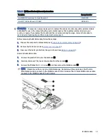
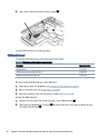
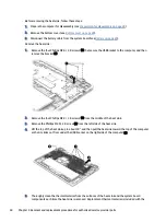
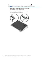


heat sink and system board spare part kits. The following illustration shows the replacement thermal
material locations.
Thermal paste is used on the heat sink (1) and system board component (2) as shown in the following
illustration.
To install the heat sink, reverse this procedure.
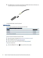
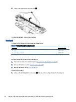
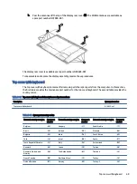
Power connector cable
To remove the power connector cable, use this procedure and illustration.
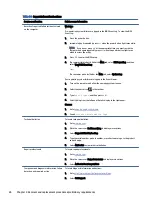
Table 5-10
Power connector cable description and part number
Description
Spare part number
Power connector cable
N02674-001
Power connector bracket (in Bracket Kit)
N07102-001
Before removing the power connector cable, follow these steps:
1.
Prepare the computer for disassembly (see
Preparation for disassembly on page 28
2.
Remove the bottom cover (see
3.
Disconnect the battery cable from the system board (see
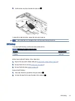
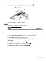
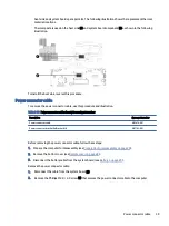
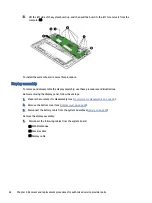
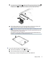
Remove the power connector cable:
1.
Disconnect the cable from the system board (1).
2.
Remove the Phillips M2.0 × 4.0 screw (2) that secures the power connector cable to the computer.
Power connector cable
39


