


HP Pro 3015 Illustrated Parts & Service Map, MT chassis
597659-001
page 3
Password Security
Resetting the password jumper
1. Shut down the operating system properly, then turn off the computer and any external devices,
and disconnect the power cord from the power outlet.
2. With the power cord disconnected, press the power button again to drain the system of any
residual power.
3. Remove the access panel.
4. Locate the header and jumper labeled
CLEAR PW
.
5. Remove the jumper from pins 2 and 3. Place the jumper on pins 1 and 2.
6. Replace the access panel.
7. Reconnect the external equipment.
8. Plug in the computer and turn on power. Allow the operating system to start. This clears the
current passwords and disables the password features.
9. To establish new passwords, repeat steps 1 through 4, replace the password jumper on pins 2
and 3, then repeat steps 6 through 8. Establish the new passwords in Computer Setup. Refer to
the
Computer Setup (F10) Utility Guide
for Computer Setup instructions.
Resetting the CMOS jumper
1. Turn off the computer and any external devices, and disconnect the power cord from the
power outlet. The power must be disconnected from the system to clear CMOS.
2. Disconnect the keyboard, monitor, and any other external equipment connected to the
computer.
3. Remove the access panel.
4. Locate the header and jumper labeled
CLEAR CMOS
.
5. Remove the CMOS jumper from pins 2 and 3 and put the jumper on pins 1 and 2. This clears
CMOS.
6. Put the jumper back on pins 2 and 3.
7. Replace the access panel.
8. Reconnect the external equipment.
9. Plug in the computer and turn on power.
NOTE: Use Computer Setup to reset any special system setups along with the date and time.
For instructions on Computer Setup, see the
Computer Setup (F10) Utility Guide
.
System Setup and Boot
Basic system information regarding system information, setup, power management, hardware,
and passwords is maintained in the Setup Utility held in the system ROM. The Setup Utility is
accessed by pressing the F10 key when prompted (on screen) to do so during the boot sequence.
If the screen prompt opportunity is missed, a restart will be necessary...
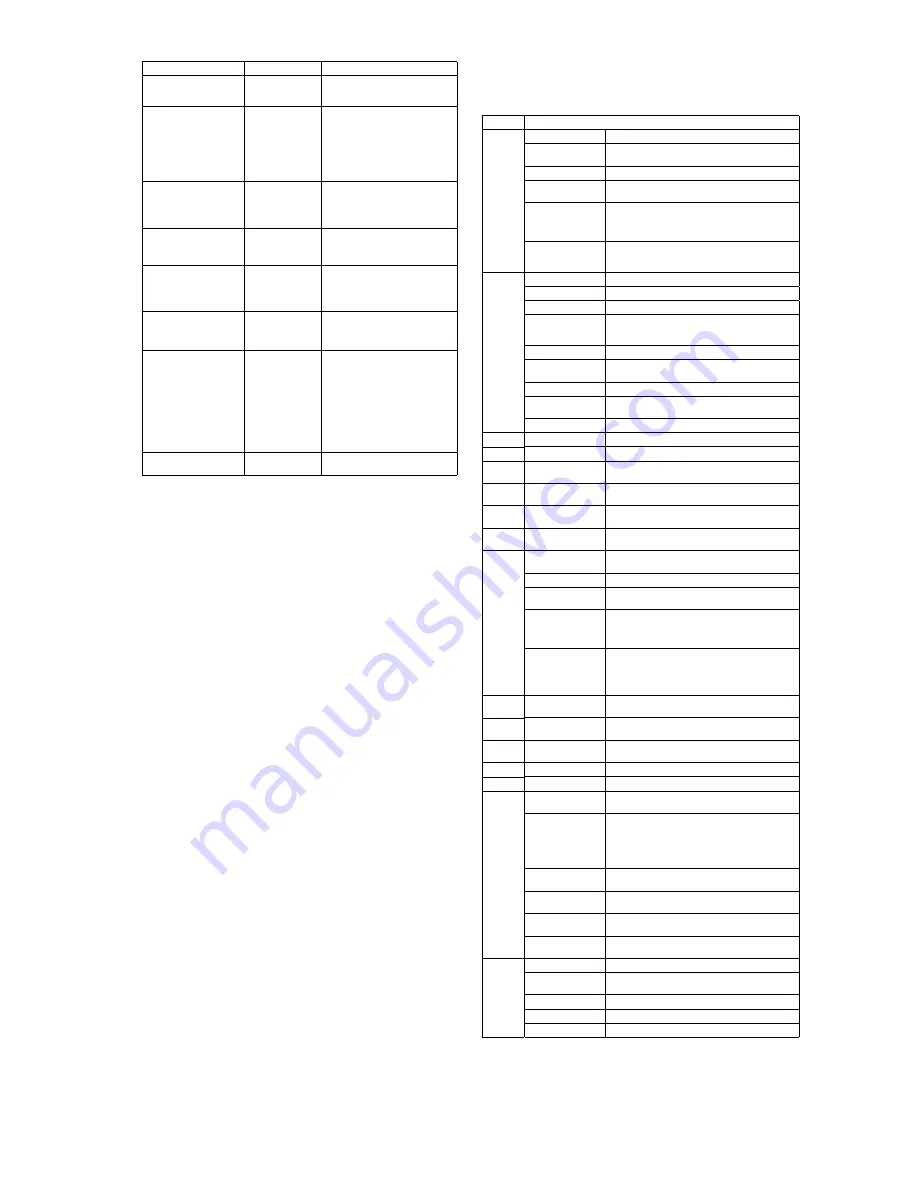
POST Audible Codes
Beeps
Meaning
Recommended Action
1 short beep and 1 long beep
followed by a three second
pause
Bad memory or
memory configura-
tion error.
Check that the memory modules have
been installed correctly and that proper
modules are used.
2 short beeps and 1 long
beep followed by a three
second pause
No graphics card
installed or graphics
card initialization
failed.
For systems with a graphics card:
1. Reseat the graphics card. Power on
the system.
2. Replace the graphics card.
3. Replace the system board.
For systems with integrated graphics,
replace the system board.
3 short beeps and 1 long
beep followed by a three
second pause
CPU configuration
error or invalid CPU
detected before
graphics card initial-
ized.
1. Upgrade the BIOS to proper ver-
sion.
2. Change the processor.
1 short beep followed by a
one second pause
No optical drive
found.
1. Check cable connections.
2. Run the Computer Setup utility and
ensure the device port is enabled.
2 short beeps followed by a
three second pause
No CD found.
1. Check the type of drive that you are
using and use the correct media
type.
2. Replace the CD with a new one.
3 short beeps followed by a
three second pause
Flashing not ready
(missing utility or
BIOS image file,
etc.)
Upgrade the BIOS to proper version.
4 short beeps followed by a
three second pause
Flashing operation
has failed (checksum
error, corrupted
image, etc.)
1. Verify the correct ROM.
2. Flash the ROM if needed.
3. If an expansion board was recently
added, remove it to see if the prob-
lem remains.
4. Clear CMOS.
5. If the message disappears, there may
be a problem with the expansion
card.
6. Replace the system board.
5 short beeps followed by a
three second pause
BIOS recovery was
successful
No action required.
Computer Setup Menu
Heading
Option / Description
Main
System Time
Allows you to set system time.
System Date
Allows you to set system date.
Language
Allows you to select the language.
Floppy Diskette A
Allows you to set to Disabled, 1.44 MB 3.5”, Not
Installed.
1st Drive
2nd Drive
3rd Drive*
4th Drive*
Allow you to: Enable/disable port configuration, view
capacity, transfer mode. Also allows you to run HDD
self-test for selected channel: SMART status check,
SMART short self test, SMART extended self test.
System Information
Allows you to view installed memory, memory banks 1-
4, BIOS revision, core version, model number, product
number, serial number, asset tag (press
Enter
to change)
Advanced
CPU Type
View only.
CPU Speed
View only.
Cache RAM
View only.
Primary Video
Adapter
Allows you to select boot display device when more
than 2 video options are offered by system: Integrated
(Onboard), PCI, PCI-Ex16, PCI-Ex1, Onboard.
SATA Controller
Allows you to disable/enable the SATA controller.
SATA Controller
Mode
If SATA1 Controller is enabled, allows you to set the
mode to: IDE, AHCI
Onboard LAN
Disable/enable onboard LAN controller.
Onboard LAN Boot
ROM
Disable/enable the boot ROM of the onboard LAN chip.
Onboard 1394
Allows you to disable/enable onboard 1394 port.
Supervisor Password
Allows you to view the supervisor password.
User Password
Allows you to view the user password.
Onboard Audio
Allows you to set the onboard audio to: Enabled, Dis-
abled, Auto.
Microphone Input
Allows you to disable/enable the onboard microphone
port.
USB Ports
Allows you to disable/enable individual USB ports
(USB Port 1 through USB Port 12).
Change Supervisor
Password
Allows you to change the supervisor password.
Power
After AC Power Fail-
ure
Allows you to select system restart behavior after power
loss: Stay off, Power on, Auto.
NX (No Execute)
Disable/enables the processors NX feature.
Virtualization Tech-
nology
Disable/enable.
S5 Maximum Power
Savings
Disables/enables S5 Maximum Power Savings. Enabling
this feature reduces the power of this system as much as
possible in the S5 state. This feature must be disabled if
you want to enable Wake on LAN from S5.
Wake on LAN from
S5
Disables/enables limited Wake on LAN from S5. Note
that the computer can only wake from S5 during a nor-
mal shutdown event. The S5 Maximum Power Savings
feature must be disabled in order to enable limited Wake
on LAN from S5.
Boot
Boot-time Diagnostic
Screen
Disable/enable POST diagnostic messages display.
Esc: Boot Menu
Disables/enables POST Esc: Boot Menu message dis-
play,
F9: Diagnostics
Disables/enables POST F9: Diagnostics message dis-
play,
F10: Setup
Disables/enables POST F10: Setup message display,
F11: Recovery
Disables/enables POST F11: Recovery message display,
F12: Boot from LAN
Disables/enables POST F12: Boot From LAN message
display,
(Boot Device Priority)
1st Boot Device, 2nd
Boot Device, 3rd
Boot Device, 4th Boot
Device
Allows you to specify which device groups will boot
first, second, third, and fourth or to disable any
of the four: CD-ROM group, Hard drive group, Floppy
group, Network boot group. MS-DOS drive lettering
assignments maybe apply after a non-MS-DOS operat-
ing system has started.
Floppy Group Boot
Priority
Specifies boot device priority within removable devices.
CD-ROM Boot Prior-
ity
Specifies boot device priority within CD/DVD drives.
Hard Drive Boot Pri-
ority
Specifies boot device priority within hard drives.
Network Group Boot
Priority
Specifies boot device priority within bootable network
devices.
Exit
Exit Saving Changes
Press
Enter
to exit saving changes.
Exit Discarding
Changes
Press
Enter
to exit discarding changes.
Load Setup Defaults
Press
Enter
to load setup defaults.
Discard Changes
Press
Enter
to discard changes.
Save Changes
Press
Enter
to save changes.


