background image

United States     December 16, 2002 


Maintenance & Service Guide

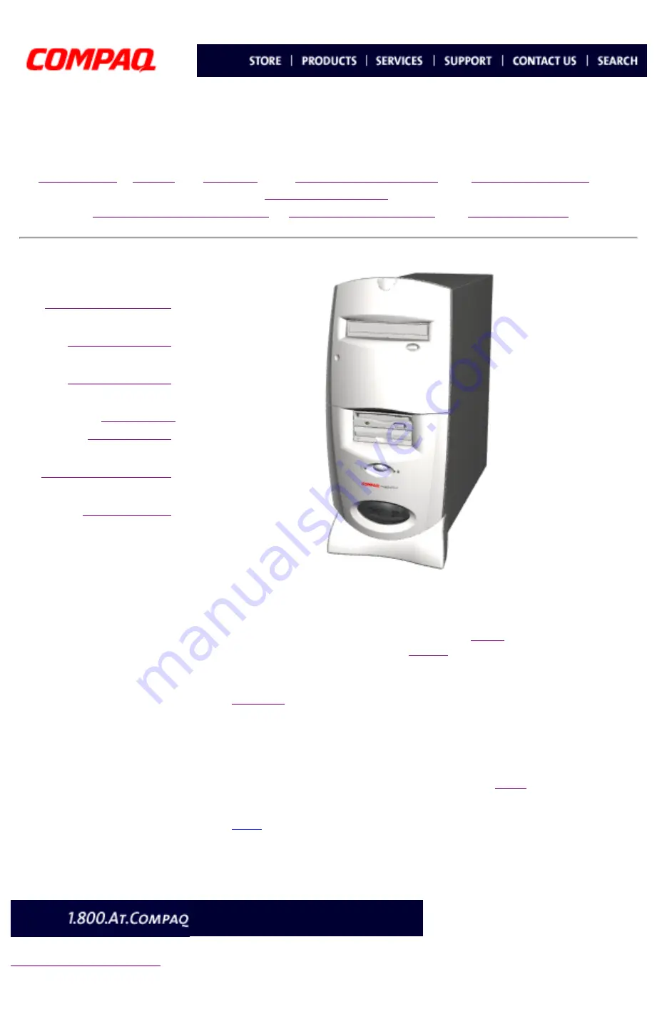
Presario 5800 Series Personal Computers

MSG Index

 | 

Home

  |   

Preface

    |   

Product Description

   |   

Troubleshooting

   |   

Illustrated Parts 


Removal & Replacement

 |  

Jumpers & Switches

   |   

Specifications


Product Description

Troubleshooting

Illustrated Parts

Removal & 

Replacement

Jumpers & Switches

Specifications


Welcome to the 

Presario 5800 Series Maintenance and Service 

Guide

. This online guide is designed to serve the needs of those whose job 

it is to repair Compaq products.  Many of the components of the hardcopy 

MSG are contained in this online guide. The 

Notice

 contains the copyright 

and trademark information. The 

Preface

 shows symbol conventions, 

Technician Notes and Serial Number locations on the unit. 

Download

 a ZIP file of the complete MSG to local hard drive.

This MSG will be periodically maintained and updated as needed. 

To report a technical problem, contact your Regional Support Center or IM 

Help Center.

For content comments or questions, contact the 

Editor

.

Top


privacy and legal statement

Содержание Presario 5800 Series

Страница 1: ...guide is designed to serve the needs of those whose job it is to repair Compaq products Many of the components of the hardcopy MSG are contained in this online guide The Notice contains the copyright and trademark information The Preface shows symbol conventions Technician Notes and Serial Number locations on the unit Download a ZIP file of the complete MSG to local hard drive This MSG will be per...

Страница 2: ...by Compaq should repair this equipment All troubleshooting and repair procedures are detailed to allow only subassembly module level repair Because of the complexity of the individual boards and subassemblies the user should not attempt to make repairs at the component level or to make modifications to any printed circuit board Improper repairs can create a safety hazard Any indications of compone...

Страница 3: ... Replacement Jumpers Switches Specifications Serial Number The computer serial number should be provided to Compaq whenever requesting information or ordering spare parts The serial number is located on the back 1 and on the front of the computer behind the drive cover not shown Model may vary slightly from the one shown Back to Removal and Replacement privacy and legal statement ...

Страница 4: ...ves PCB assembly side down on the foam Top Grounding Methods The method for grounding must include a wrist strap or a foot strap at a grounded workstation When seated wear a wrist strap connected to a grounded system When standing use footstraps and a grounded floor mat Top Grounding Workstations To prevent static damage at the workstation use the following precautions Cover the workstation with a...

Страница 5: ...er Corporation 1998 Compaq Computer Corporation All rights reserved Printed in the U S A Compaq Presario Registered U S Patent and Trademark Office Microsoft MS DOS and Windows are registered trademarks of Microsoft Corporation Windows 95 is a trademark of Microsoft Corporation Windows 98 is a trademark of Microsoft Corporation The software described in this guide is furnished under a license agre...

Страница 6: ...fications Product Description Product Description Models and Features CPU Controls Lights Keyboards CPU Back Connectors Digital Creativity Imaging Center DCIC Creativity Action Center CAC Power Management Power Cord Requirements This section describes the models and features of the Compaq Presario 5800 Series of personal computers Use the navigation bar at left to find specific features privacy an...

Страница 7: ... V 90 K 56k V 90 GW 56k V 90 Model Processor MHz Memory MB Hard Drive GB Primary Optical Second Optical Video Memory MB Modem U S Latin America Canada Europe Middle East Africa Asia Pacific Back to Product Description privacy and legal statement 5822Celeron 50096136xDVDN AN AGW 5827Celeron 500961732x CD RWN AGW 5832Celeron 50096136xDVDCD RWN AGW 5834Celeron 500961732x CD RWN AGW 5835Celeron 500961...

Страница 8: ...ers Switches Specifications Product Description CPU Controls and Lights Description 1 CD or DVD Manual Eject Button 2 CD or DVD Drive Activity Light 3 CD or DVD Load Ejection Button 4 Diskette Drive Eject Button and Drive Activity Light 5 Zip Drive Eject Button and Activity Light 6 Hard Drive Activity Light 7 Power Button 8 Power Status Light Back to Product Description privacy and legal statement...

Страница 9: ...ernet Suite Buttons and Keyboard Lights Easy Access Buttons 1 Play Pause 2 Rewind Previous track 3 Fast Forward Next track 4 Stop 5 Eject 6 Print 7 Launch favorite application 8 Volume down 9 Mute 10 Volume up 11 Sleep Top Internet Suite Buttons and Keyboard Lights 1 Instant E Mail 2 Community 3 My Presario 4 Instant Internet 5 Instant Search 6 Online Marketplace 7 Retail Central 8 Number Lock Lig...

Страница 10: ...onnector Pins 1 Mouse connector 2 Keyboard connector 3 USB Universal Serial Bus connectors 4 Microphone 5 Audio in 6 Audio out 7 IEEE 1394 connector 8 VGA connector 9 Ethernet RJ45 connector 10 RJ11 connector to wall 11 RJ11 connector to telephone 12 AC power connector 13 Voltage select switch 14 Serial port 15 Parallel port 16 Digital Flat Panel connector 17 Telephone line to wall outlet 18 Telep...

Страница 11: ...n CPU Back Connectors for Models 5831 5837 5838 5855 5858 5861 5868 5875 and 5888 5800 Models with Pentium III System Board 5800 Models with Celeron System Board Connector Pins 1 Power Connector 2 Dual USB 3 Keyboard 4 Serial Port 5 IEEE 1394 Connector 6 SVGA Monitor Port 7 Microphone 8 Audio In 9 Audio Out 10 Modem Line Out 11 Modem Line In 12 Game Port 13 Parallel Port 14 Scroll Mouse Back to Pr...

Страница 12: ...rs for Models 5822 5827 5832 5834 and 5835 5800 Models with Pentium III System Board 5800 Models with Athlon System Board Connector Pins 1 Mouse connector 2 Keyboard connector 3 USB Universal Serial Bus connectors 4 Microphone in 5 Audio in 6 Audio out 7 SVGA monitor port 8 Modem 9 Ethernet RJ45 connector 10 AC power connector 11 Voltage select switch 12 Serial port 13 Parallel port On selected mo...

Страница 13: ...a Unused Ground 5 VDC Clock Unused Mouse Connector Pin Signal 1 2 3 4 5 6 Data Unused Ground 5 VDC Clock Unused Back to Top VGA Monitor Connector Pin Signal 1 2 3 4 5 6 7 8 9 10 11 12 13 14 15 Red Analog Green Analog Blue Analog Volume Up Ground Ground Analog Ground Analog Ground Analog 5 VDC Ground Volume Down DDC Data Horizontal Sync Vertical Sync DDC Clock MIDI Joystick Connector Pin Signal 1 2...

Страница 14: ...ubleshooting Illustrated Parts Removal Replacement Jumpers Switches Specifications Product Description Digital Creativity Imaging Center Creativity Action Center Description 1 Gamepad Joystick Port 2 USB Universal Serial Bus connector 3 IEEE 1394 connector Available on select models only Back to Product Description privacy and legal statement ...

Страница 15: ...ur computer into sleep mode in the Windows 98 desktop press the Sleep button on the keyboard The power status light on the CPU will light to show that Sleep mode is activated Other manual standby options Another way to put your computer into sleep mode manually under Windows 98 is to select Start then Shutdown Select Standby from the list of choices to put the system into Sleep mode The system can...

Страница 16: ...oltage rating of 125 or 250 volts AC as required by each country s power system 4 The appliance coupler must meet the mechanical configuration of an EN 60 320 IEC 320 Standard Sheet C13 connector for mating with appliance inlet on the Switch Box Country Specific Requirements Power Cord Set Requirements by Country Country Accredited Agency Applicable Note Numbers Australia EANSW 1 Austria OVE 1 Bel...

Страница 17: ...roubleshooting Without Diagnostics This section provides troubleshooting information for Compaq Presario 5800 Series Personal Computers Power On Self Test POST messages diagnostic error codes and memory error codes appear in tables The message and code tables include a description of the error the probable cause and the recommended action that should be taken to resolve the error condition Adheren...

Страница 18: ...5800 Models with Celeron System Board 5800 Models with Pentium III System Board Password Jumper Location If the power on password is not known clearing CMOS will disable the power on password To clear CMOS complete the following steps 1 Complete the preparation for disassembly 2 Remove the chassis 3 To disable the password move the jumper at J3 from 2 3 to 1 2 4 Wait for 10 seconds 5 Move the jump...

Страница 19: ... 5800 Models with Pentium III System Board 5800 Models with Athlon System Board If the power on password is not known clearing CMOS will disable the power on password To clear CMOS complete the following steps 1 Complete the preparation for disassembly 2 Remove the chassis 3 To disable the password move the jumper at JP1 from 1 2 to 2 3 4 Wait for ten seconds 5 Move the jumper at JP1 from 2 3 to 1...

Страница 20: ... Celeron System Board 5800 Models with Athlon System Board Password Jumper Location If the power on password is not known clearing CMOS will disable the power on password To clear CMOS complete the following steps 1 Complete the preparation for disassembly 2 Remove the chassis 3 To disable the password move the jumper at JP1 from 1 2 to 2 3 4 Wait for 10 seconds 5 Move the jumper at JP1 from 2 3 t...

Страница 21: ... tests that run automatically when the system is turned on After the computer is turned on POST checks the following assemblies to ensure that the computer system is functioning properly Keyboard System board Memory modules Video memory Diskette drive Hard drive CD or DVD drive Power supply POST also detects the type of mass storage devices installed in the computer If POST finds an error in the s...

Страница 22: ...up 2 Replace the diskette drive Back to Top Invalid NVRAM Media Type Probable Cause Recommended Action Problem with NVRAM CMOS access Replace the system board Back to Top Keyboard Controller Error Probable Cause Recommended Action Keyboard I O keyboard controller on system board or mouse error 1 Replace the keyboard 2 Replace the mouse 3 Replace the system board Back to Top Keyboard Error Probable...

Страница 23: ...ough 210 xx 1 Remove one memory module at a time until the error message stops 2 Replace other removed modules one at a time testing each to ensure the error does not return 3 Replace the system board and retest 204 xx Memory address test failed 206 xx Increment pattern test failed 210 xx Random pattern test failed Top Keyboard Test Error Codes Error Code Description Recommended Action 301 xx Keyb...

Страница 24: ... failed Identify command 1751 x Fixed Disk 1 failed Identify command 1760 x Fixed Disk 0 does not support Block Mode 1761 x Fixed Disk 1 does not support Block Mode 1790 x Disk 0 Configuration Error 1792 x Secondary Disk Controller Failure 1799 xx Invalid hard drive type failed Top DVD Drive Test Error Codes Error Code Description Recommended Action 3301 xx 3305 xx 66XX xx DVD drive read test fail...

Страница 25: ...Solution Hard drive error occurs Hard disk has bad sectors or has failed Replace hard drive Disk transaction problem The directory structure is bad or there is a problem with a file From the Windows desktop click on the Start button Choose Programs Accessories System Tools Scandisk to check for problems If problems exist run Scandisk and click on the Automatically fix errors checkbox at the bottom...

Страница 26: ...s Storage Cables Boards Modems Keyboards Mouse Monitors Miscellaneous Hardware Kit Return Kits Documentation This section provides illustrated parts and a reference for spare parts numbers for Compaq Presario 5800 Series Personal Computers When requesting information or ordering spare parts the computer serial number should be provided to Compaq The serial number is displayed on the back of the ch...

Страница 27: ...Miscellaneous Hardware Kit Return Kits Documentation System Unit Description Spare Part Number 1 Front bezel assembly 159768 001 2 Cover assembly 148941 001 3 Model logo plate 102382 001 4 Door assembly 158240 001 5 Lightpipe and button board assembly 157286 001 6 DCIC CAC cover 102370 001 7 Drive bay bezel blank 5 25 in 102371 001 8 Floppy bezel 102369 001 9 Drive bay bezel blank 3 5 in 102368 00...

Страница 28: ...ment Jumpers Switches Specifications Illustrated Parts Mass Storage Devices Illustrated Parts System Unit Mass Storage Cables Boards Fax Modems Keyboards Mouse Monitors Miscellaneous Hardware Kit Return Kits Documentation 3 5 in 1 44 MB Diskette Drive 136436 001 3 5 in Hard Drive privacy statement legal notices 100MB Zip Drive 135568 001 DVD ROM Drive 8x Max 153771 001 8 GB HD 134127 001 ...

Страница 29: ... Return Kits Documentation Power Cord Diskette Data Cable 238078 003 Fax Modem Cable Cables Cables not shown Spare Part Number CD DVD Cable 238477 009 Modem Adapter Cable 340398 xxx Click on the box to find the dash number for the modem adapter cable for a specific location Internal Cables not shown Spare Part Number Hard Drive Cable ATA66 270847 013 Parallel Port Cable 264380 003 CD ROM Audio Cab...

Страница 30: ...els with Pentium III System Board An example of the type of board used is illustrated Board may vary slightly from the one shown Illustrated Parts System Unit Mass Storage Cables Boards Fax Modems Keyboards Monitors Miscellaneous Hardware Kit Return Kits Documentation Boards Description Spare Part Number 1 Processor K7 500 K7 550 K7 600 K7 650 K7 700 155213 001 155214 001 155215 001 160396 001 160...

Страница 31: ...n System Board 5800 Models with Pentium III System Board An example of the type of board used is illustrated Board may vary slightly from the one shown Illustrated Parts System Unit Mass Storage Cables Boards Fax Modems Keyboards Mouse Monitors Miscellaneous Hardware Kit Return Kits Documentation Boards Description Spare Part Number 1 Processor Celeron 466 MHz 500 MHz 138158 001 149267 001 2 32 MB...

Страница 32: ... Board 5800 Models with Athlon System Board An example of the type of board used is illustrated Board may vary slightly from the one shown Illustrated Parts System Unit Mass Storage Cables Boards Fax Modems Keyboards Monitors Miscellaneous Hardware Kit Return Kits Documentation Boards Description Spare Part Number 1 Processor Pentium III 500 MHz 550 MHz 600 MHz 153840 001 153841 001 152818 001 2 3...

Страница 33: ...arts Fax Modems Three examples of the types of modems used are illustrated Your modem may vary slightly from those shown Illustrated Parts System Unit Mass Storage Cables Boards Fax Modems Keyboards Mouse Monitors Miscellaneous Hardware Kit Return Kits Documentation PCI V 90 DSL 157041 001 D International Modem 56k V 90 157123 002 APD EMEA International Modem 56Kbps V 90 334808 021 K 56Kbps V 90 1...

Страница 34: ...ions Illustrated Parts Keyboards Mouse Illustrated Parts System Unit Mass Storage Cables Boards Fax Modems Keyboards Mouse Monitors Miscellaneous Hardware Kit Return Kits Documentation Keyboards Mouse Description Spare Part Numbers Internet Keyboard 387084 xxx Click on the box below to determine the dash number for the keyboard for a particular location Logitech scroll mouse 334689 002 privacy and...

Страница 35: ...s Removal Replacement Jumpers Switches Specifications Illustrated Parts Monitors Illustrated Parts System Unit Mass Storage Cables Boards Fax Modems Keyboards Mouse Monitors Miscellaneous Hardware Kit Return Kits Documentation Compaq MV520 15 inch monitor 105782 001 Compaq MV720 17 inch monitor 105784 001 Compaq MV920 19 inch monitor 105786 001 privacy and legal statement ...

Страница 36: ...ions Illustrated Parts Miscellaneous Hardware Kit Illustrated Parts System Unit Mass Storage Cables Boards Fax Modems Keyboards Mouse Monitors Miscellaneous Hardware Kit Return Kit Documentation Miscellaneous Hardware Kit Description Spare Part Number Miscellaneous Hardware Kit for Models 5831 5837 5838 5855 5858 5861 5868 5875 and 5890 155689 001 Miscellaneous Hardware Kit for Models 5822 5827 58...

Страница 37: ...ting Illustrated Parts Removal Replacement Jumpers Switches Specifications Illustrated Parts Return Kit Illustrated Parts System Unit Mass Storage Cables Boards Fax Modems Keyboards Mouse Monitors Miscellaneous Hardware Kit Return Kit Documentation Return Kits Description Spare Part Number Return Kit for 5800 series computers North America 128389 001 ...

Страница 38: ... 5861 U K 127626 031 Quick Restore Presario 5838 5855 5861 5868 and 5890 U S 127626 001 Quick Restore Presario 5830 5831 and 5861 France 127626 051 Quick Restore Presario 5830 5831 and 5861 Italy 127626 061 Quick Restore Presario 5831 5838 and 5861 Denmark 127626 061 Quick Restore Presario 5830 5831 and 5861 Norway 127626 091 Quick Restore Presario 5830 5831 and 5861 Sweden 127626 101 Quick Restor...

Страница 39: ...tile Disk DVD from the computer 2 Turn off the computer and any peripheral devices that are connected to the computer CAUTION Hold the power button for approximately four seconds or use the shutdown command in Windows to turn off the system before you disconnect any cables 3 Disconnect the power cord from the electrical outlet then from the computer 4 Disconnect all peripheral device cables from t...

Страница 40: ...Imaging Center Option Card Retainer Graphics Board PCI Cards Memory Processor Processor Retention Clips RTC Battery System Board Cables System Board Parallel Port Back I O Panel Power Supply Removing the Chassis 1 Complete the preparation for disassembly procedures 2 Remove five screws from the back of the computer 3 Grasp the handle on back of the computer chassis and pull back to separate from c...

Страница 41: ...cations Removal and Replacement Removal Sequence Chassis Mass Storage Devices Button Board Digital Creativity Imaging Center Option Card Retainer Graphics Board PCI Cards Memory Processor Processor Retention Clips RTC Battery System Board Cables System Board Parallel Port Back I O Panel Power Supply Mass Storage Devices Index 1 CD RW DVD Drive 2 Zip Drive 3 Diskette Drive 4 Hard Drive privacy stat...

Страница 42: ...ated Parts Removal Replacement Jumpers Switches Specifications Removal and Replacement Mass Storage Devices CD RW DVD Drive Zip Drive Diskette Drive Hard Drive Mass Storage Devices Index Removing the CD RW DVD Drive 1 Complete preparation for disassembly procedures 2 Remove the chassis 3 Disconnect audio data and power cables Next Step privacy and legal statement ...

Страница 43: ...oval and Replacement Mass Storage Devices CD RW DVD Drive Zip Drive Diskette Drive Hard Drive Mass Storage Devices Index Removing the CD RW DVD Drive continued 4 Remove two screws from the right side and two screws from the left side of the CD DVD Drive 5 Remove the CD DVD Drive from the drive bay Replacement To replace the CD DVD Drive reverse the removal procedure Return to Removal and Replaceme...

Страница 44: ...trated Parts Removal Replacement Jumpers Switches Specifications Removal and Replacement Mass Storage Devices CD RW DVD Drive Zip Drive Diskette Drive Hard Drive Mass Storage Devices Index Removing the Zip Drive 1 Complete the preparation for disassembly procedures 2 Remove the chassis 3 Disconnect the data and power cables Next Step privacy and legal statement ...

Страница 45: ...ations Removal and Replacement Mass Storage Devices CD DVD Drive CD RW Drive Zip Drive Diskette Drive Hard Drive Mass Storage Devices Index Removing the Zip Drive continued 4 Remove the two screws from the right side and the two screws from the left side of the Zip Drive 5 Grasp the Zip Drive and remove from the drive bay Replacement To replace Zip Drive reverse the removal procedure Return to Rem...

Страница 46: ...ted Parts Removal Replacement Jumpers Switches Specifications Removal and Replacement Mass Storage Devices CD DVD Drive CD RW Drive Zip Drive Diskette Drive Hard Drive Mass Storage Devices Index Removing the Diskette Drive 1 Complete preparation for disassembly procedures 2 Remove chassis 3 Disconnect the power and data cables Next Step privacy and legal statement ...

Страница 47: ... Mass Storage Devices CD DVD Drive CD RW Drive Zip Drive Diskette Drive Hard Drive Mass Storage Devices Index Removing the Diskette Drive continued 4 Remove the two screws from the right side and the two screws from the left side of the Diskette Drive bay 5 Pull the Diskette Drive straight back out of the drive bay Replacement To replace the Diskette Drive reverse the removal procedure Return to R...

Страница 48: ...ooting Illustrated Parts Removal Replacement Jumpers Switches Specifications Removal and Replacement Hard Drives 5 25 Inch drive 3 5 Inch drive The Compaq Presario 5800 Series Computers may be equipped with 5 25 inch or 3 5 inch form factor hard drives Refer to the disassembly instructions for the model you are servicing privacy and legal statement ...

Страница 49: ...ts Removal Replacement Jumpers Switches Specifications Removal and Replacement Mass Storage Devices CD DVD Drive CD RW Drive Zip Drive Diskette Drive Hard Drive Mass Storage Devices Index Removing the 5 25 Inch Hard Drive 1 Complete the preparation for disassembly procedures 2 Remove the chassis 3 Disconnect the data and power cables Next Step privacy and legal statement ...

Страница 50: ...ns Removal and Replacement Mass Storage Devices CD DVD Drive CD RW Drive Zip Drive Diskette Drive Hard Drive Mass Storage Devices Index Removing the 5 25 Inch Hard Drive continued 4 Remove the two screws from the chassis and the two screws from the Hard Drive supports 5 Slide the Hard Drive forward and lift up from the chassis Replacement To replace the Hard Drive reverse the removal procedure pri...

Страница 51: ...ts Removal Replacement Jumpers Switches Specifications Removal and Replacement Mass Storage Devices CD DVD Drive CD RW Drive Zip Drive Diskette Drive Hard Drive Mass Storage Devices Index Removing the 3 5 Inch Hard Drive 1 Complete the preparation for disassembly procedures 2 Remove the chassis 3 Disconnect the data and power cables Next Step privacy and legal statement ...

Страница 52: ...ement Mass Storage Devices CD DVD Drive CD RW Drive Zip Drive Diskette Drive Hard Drive Mass Storage Devices Index Removing the 3 5 Inch Hard Drive continued 4 Remove the two screws from the right side and the two screws from the left side of the Hard Drive supports 5 Slide Hard Drive inward to remove from chassis Replacement To replace the Hard Drive reverse the removal procedure Return to Remova...

Страница 53: ... on model Removal Sequence Chassis Mass Storage Devices Button Board Digital Creativity Imaging Center Option Card Retainer Graphics Board PCI Cards Memory Processor Processor Retention Clips RTC Battery System Board Cables System Board Parallel Port Back I O Panel Power Supply Removing the Button Board 1 Complete the preparation for disassembly procedures 2 Remove the chassis 3 Disconnect button ...

Страница 54: ...ces Button Board Digital Creativity Imaging Center Option Card Retainer Graphics Board PCI Cards Memory Processor Processor Retention Clips RTC Battery System Board Cables System Board Parallel Port Back I O Panel Power Supply Removing the Button Board continued 4 Remove the two screws from button board assembly and remove assembly from back of the front bezel Replacement To replace the button boa...

Страница 55: ...rd Digital Creativity Imaging Center Option Card Retainer Graphics Board PCI Cards Memory Processor Processor Retention Clips RTC Battery System Board Cables System Board Parallel Port Back I O Panel Power Supply Removing the Digital Creativity Imaging Center 1 Complete the preparation for disassembly procedures 2 Remove the chassis 3 Disconnect Digital Creativity Imaging Center cable from the sys...

Страница 56: ...ard Retainer Graphics Board PCI Cards Memory Processor Processor Retention Clips RTC Battery System Board Cables System Board Parallel Port Back I O Panel Power Supply Game port not available all models Removing the Digital Creativity Imaging Center continued 4 Remove EMI gasket not shown from the front of DCIC port 5 Remove the screw holding the DCIC port to the chassis 6 Slide port to the left t...

Страница 57: ...ty Imaging Center Option Card Retainer Graphics Board PCI Cards Memory Processor Processor Retention Clips RTC Battery System Board Cables System Board Parallel Port Back I O Panel Power Supply Removing the Option Card Retainer 1 Complete the preparation for disassembly procedures 2 Remove the chassis 3 Remove the two screws from the Option Card Retainer and remove retainer from chassis Replacemen...

Страница 58: ...al Creativity Imaging Center Option Card Retainer Graphics Board PCI Cards Memory Processor Processor Retention Clips RTC Battery System Board Cables System Board Parallel Port Back I O Panel Power Supply Removing the Graphics Board 1 Complete the preparation for disassembly procedures 2 Remove the chassis 3 Remove the Option Card Retainer 4 Pull the Graphics Board and bracket out and to the right...

Страница 59: ... Back I O Panel Power Supply Illustration shows Fax Modem card NOTE All PCI Cards Fax Modem Audio NIC and Home PNA have the same removal procedures Location of PCI Cards are as follows Audio card in the third slot from the left Fax Modem card in the fifth slot from the left NIC card in the sixth slot from the left Home PNA card in the seventh slot from the left Removing the PCI Card 1 Complete the...

Страница 60: ...enter Option Card Retainer Graphics Board PCI Cards Memory Processor Processor Retention Clips RTC Battery System Board Cables System Board Parallel Port Back I O Panel Power Supply Removing the Memory Module 1 Complete the preparation for disassembly procedure 2 Remove the chassis 3 Press outward on the release latches found on both ends of the Dual Inline Memory Module DIMM 4 Detach Memory Modul...

Страница 61: ...quence Chassis Mass Storage Devices Button Board Digital Creativity Imaging Center Option Card Retainer Graphics Board PCI Cards Memory Processor Processor Retention Clips RTC Battery System Board Cables System Board Parallel Port Back I O Panel Power Supply Removing the Processor 1 Complete the preparation for disassembly procedures 2 Remove the chassis 3 Disconnect fan cable on the processor fro...

Страница 62: ...Storage Devices Button Board Digital Creativity Imaging Center Option Card Retainer Graphics Board PCI Cards Memory Processor Processor Retention Clips RTC Battery System Board Cables System Board Parallel Port Back I O Panel Power Supply Removing the Processor 1 Complete the preparation for disassembly procedures 2 Remove the chassis 3 Pull release tabs outward on the ends of the processor retent...

Страница 63: ...rd PCI Cards Memory Processor Processor Retention Clips RTC Battery System Board Cables System Board Parallel Port Back I O Panel Power Supply Removing the Processor 1 Complete the preparation for disassembly procedures 2 Remove the chassis Caution The processor may still be very hot if the computer has been running recently 3 Remove the clip from the heat sink 4 Lift up the ZIF socket handle then...

Страница 64: ...on Card Retainer Graphics Board PCI Cards Memory Processor Processor Retention Clips RTC Battery System Board Cables System Board Parallel Port Back I O Panel Power Supply Removing the Processor Retainer Clips 1 Complete the preparation for disassembly procedures 2 Remove the chassis 3 Remove the Processor 4 Loosen the four push pins from the processor retainer clips Note Use needle nose pliers or...

Страница 65: ... Cards Memory Processor Processor Retention Clips RTC Battery System Board Cables System Board Parallel Port Back I O Panel Power Supply Removing the RTC Battery 1 Perform the preparation for disassembly procedure 2 Remove the chassis 3 Push out the socket lever and slide the RTC battery out of the socket Replacement To replace the RTC battery reverse the removal procedure WARNING The clock CMOS l...

Страница 66: ...ainer Graphics Board PCI Cards Memory Processor Processor Retention Clips RTC Battery System Board Cables System Board Parallel Port Back I O Panel Power Supply Removing the System Board Cables 1 Fan Cable J9 system board connector 2 CD DVD Audio cable J5 H3 and J4 system board connectors 3 Power Cable J8 system board connector 4 Data Cables J5 J6 and J7 system board connectors 5 Button Board Cabl...

Страница 67: ...rocessor Processor Retention Clips RTC Battery System Board Cables System Board Parallel Port Back I O Panel Power Supply Removing the System Board Cables 1 Parallel Port Cable J8 system board connector 2 Fan Cable J15 system board connector 3 CD DVD Audio Cable J17 system board connector 4 Power Cable J9 system board connector 5 Data Cables J12 J13 J14 system board connectors 6 Button Board Cable...

Страница 68: ...pply Removing the System Board 1 Complete the preparation for disassembly procedures 2 Remove the chassis 3 Remove the Graphics Board on selected models only 4 Remove the Fax Modem 5 Remove Networking Interface Card on select models only 6 Remove the Audio Card on select models only 7 Remove the Memory 8 Remove the Processor 9 Remove the Processor Retention Clips 10 Disconnect the System Board Cab...

Страница 69: ... Card Retainer Graphics Board PCI Cards Memory Processor Processor Retention Clips RTC Battery System Board Cables System Board Parallel Port Back I O Panel Power Supply Removing the Parallel Port 1 Complete the preparation for disassembly procedures 2 Remove the chassis 3 Disconnect the parallel cable from connector on the system board 4 Remove the screwlocks that secure the Parallel Port to the ...

Страница 70: ...Clips RTC Battery System Board Cables System Board Parallel Port Back I O Panel Power Supply Removing the Back I O Panel 1 Complete the preparation for disassembly procedures 2 Remove the chassis 3 Remove the Graphics Board On select models only 4 Remove the Fax Modem 5 Remove the Networking Interface Card on select models only 6 Remove the Audio Card on select models only 7 Remove the Memory 8 Re...

Страница 71: ...ete the preparation for disassembly procedures 2 Remove the chassis 3 Remove 5 25 Inch or 3 5 Inch Hard Drive 4 Disconnect System Board Cables 5 Disconnect power supply cables from CD DVD Zip drive Diskette and Hard Drive 6 Remove Graphics Board on select models only 7 Remove the Fax Modem 8 Remove Networking Interface Card on select models only 9 Remove the Audio Card on select models only 10 Rem...

Страница 72: ...n Jumper Switch Information 5800 Models with Athlon System Board 5800 Models with Celeron System Board 5800 Models with Pentium III System Board Mass Storage 3 5 Inch Hard Drive 5 25 Inch Hard Drive DVD Drive CD Drive This section contains jumper and switch information for system board jumpers system I O board connectors and Mass Storage drives Click on a selection on the left navigation bar for j...

Страница 73: ...ual USB Connector J23 Keyboard Miniature 6 Pin 1 2 J24 Mouse Miniature 6 Pin 1 2 J24 CMOS Clear 3 Pin Header J3 DIMM Sockets 168 Pin DIMM S1 S2 S3 Button Light Board 7 Pin Header J1 Power Supply 20 Pin ATX Power Header J8 Replacement Battery Battery Holder CR2032 battery type B1 Primary IDE Drive Hard Drive 40 Pin Header Key 20 J6 Secondary IDE Drive CD Drive 40 Pin Header Key 20 J7 Diskette Drive...

Страница 74: ...Description Troubleshooting Illustrated Parts Removal Replacement Jumpers Switches Specifications Presario 5800 Models with Celeron System Board This board has no jumper settings except for clearing CMOS Jumper location JP1 CMOS Jumper Settings CMOS Normal CMOS Clear Pins 1 2 Pins 2 3 Back to Jumpers privacy and legal statement ...

Страница 75: ...dary IDE Drive J13 5 Diskette Drive J14 6 Fan Connector 4 Pin J16 7 Fan Connector 3 Pin J20 8 Button Board J10 9 CMOS Jumper JP1 10 RTC Battery Battery holder BT1 11 ISA Slot ISA Connector ISA1 12 On board Audio Disable JP6 13 PCI Slots PCI Connector PCI 1 to 5 14 CD Audio J17 15 AGP Slot AGP1 16 Frequency Multiple Jumpers JP2 17 Slot 1 J18 18 Heatsink Fan Connector J15 19 ATX Power Supply Connect...

Страница 76: ...rio 5800 Series Personal Computers MSG Index Home Preface Product Description Troubleshooting Illustrated Parts Removal Replacement Jumpers Switches Specifications 3 5 Inch Hard Drive Back to Jumpers 5 25 Inch Hard Drive Back to Jumpers privacy and legal statement ...

Страница 77: ...G Index Home Preface Product Description Troubleshooting Illustrated Parts Removal Replacement Jumpers Switches Specifications Digital Versatile Disk Drive Settings may vary depending on vendor Back to Jumpers CD Drive Settings may vary depending on vendor Back to Jumpers privacy and legal statement ...

Страница 78: ...5 100 120 140 160 800 600 8 16 24 32 56 60 72 75 85 100 120 140 160 1024 768 8 16 24 32 60 72 75 85 100 120 1152 864 8 16 24 32 60 72 75 85 100 120 1280 1024 8 16 24 32 60 70 72 75 85 100 1600 1200 8 16 24 32 60 65 70 75 80 85 100 1920 1440 8 16 24 32 60 75 2048 1536 8 16 24 60 75 The Compaq FP720 display supports a maximum resolution of 1024x768 and only supports the 60 Hz refresh rate The Compaq...

Страница 79: ...H BRIDGE 4C 7 0 00A0 Interrupt Controller 2 Control Register 00A1 Interrupt Controller 2 Mask Register 00A2 00B1 00B4 00BF 00C0 00DF DMA Controller 2 00E0 ESS Index Register 00E1 ESS Data Register 00E2 00E3 DDC2 Registers 00E4 00E5 Master I2C Interface 00E6 TV MPEG Configuration Register 00E7 00E9 00EA Ultra I O Index Register 00EB Ultra I O Data Register 00EC 00EF Modem configuration 00F0 00F1 Co...

Страница 80: ... V output 0 07 A on 12 V output 1 4 A on 5 0 V output 0 07 A on 12 V output Ambient Temperature Range Operating 50 to 122 F 10 to 50 C Storage 40 to 151 F 40 to 66 C Dielectric Voltage Withstand Input to Ground 1500 VAC 1 second Safety Standard UL 1950 CSA 22 2 950 TUV VDE EN 60 950 VDE0805 11 91 EMKO TSE 74 SEC 207 94 Input Transient Susceptibility Common and Differential Mode superimposed on AC ...

Страница 81: ...90 K56Flex V 34 V 32terbo V 32bis V 32 V 22bis V 22 V 21 Bell 212A Bell 103 V 90 K56Flex V 34 V 32terbo V 32bis V 32 V23 V 22bis V 22 V 21 Bell 212A Bell 103 V 90 K56Flex V 34 V 32terbo V 32bis V 32 V 22bis V 22 V 23 V 21 Bell 212A Bell 103 Error Correction V 42bis V 42 LAPM and MNP 2 5 V 42 LAPM and MNP 2 4 V 42 and MNP2 4 Fax V 17 14 4 kbps transmission speed V 29 V 27ter V 21 Channel 2 Class 1 ...

Отзывы: