


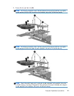


6.
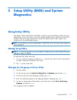
Disconnect the fan cable
(1)
from the system board.
7.
Loosen the captive screws
(2)
that secure the fan and heat sink to the system board. (Computer
models equipped with an AMD processor have three captive screws. Computer models equipped
with an Intel processor have four captive screws.)
NOTE:
Due to the adhesive quality of the thermal material located between the heat sink and
system board components, it may be necessary to move the heat sink from side to side to
detach it.
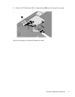
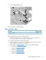
8.
Remove the fan and heat sink
(3)
.
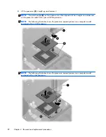
NOTE:
The following illustration shows the fan and heat sink removal process on a computer
model equipped with an AMD processor and a graphics subsystem with UMA memory.
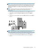
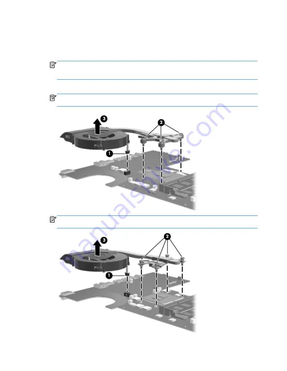
NOTE:
The following illustration shows the fan and heat sink removal process on a computer
model equipped with an Intel processor and a graphics subsystem with UMA memory.
86
Chapter 4 Removal and replacement procedures
Содержание Pavilion g7
Страница 1: ...HP Pavilion g7 Notebook PC Maintenance and Service Guide ...
Страница 4: ...iv Safety warning notice ...
Страница 8: ...viii ...
Страница 17: ...2 External component identification 9 ...
Страница 27: ...Computer major components Computer major components 19 ...