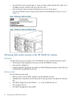
7.
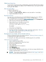
Image the SAN/iQ software.
Image the SAN/iQ software
IMPORTANT:
If the server blade accidentally power-cycles during the SAN/iQ software imaging
process, you cannot successfully resume or restart the imaging. You must begin with
the server blade with the SAN/iQ software” (page 15)
.
1.
Log in to the iLO for the server blades.
2.
Mount the HP P4000 Storage System Quick Restore
.iso
using Virtual Mount.
3.
When prompted, insert the USB flash drive containing the license key file.
NOTE:
Use the iLO Dongle (delivered with the HP P4800 G2 solution) to convert the USB
flash drive into a USB port so that you can plug in the USB key.
4.
When prompted to identify the OS version to install, enter
Y
.
IMPORTANT:
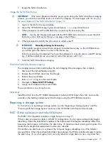
Manually entering the license key
If the installer program cannot find a properly formatted license key on the USB flash drive,
you will be given the chance to enter in the license key.
Enter the license key if prompted. You have three attempts to correctly enter a valid HP license
key. If all three attempts are unsuccessful, restart the process with
5.
Finish the SAN/iQ software imaging.
Finish the SAN/iQ software imaging
The imaging process starts and displays the Auto Imaging Done message when complete.
1.
Disconnect the Virtual Media using iLO.
2.
Remove the USB flash drive from the Dongle.
3.
Reboot the server blades.
4.
Enter
start
to log into the server blade.
5.
Navigate to
Network TCP/IP Settings
.
6.
Assign an IP address to the server blade.
The server blade is now ready for use.
Next steps
Install the CMC from the HP P4000 Management Software DVD. Open the CMC, and use the
wizards on the Getting Started Launch Pad to begin using the HP P4800 G2 solution.
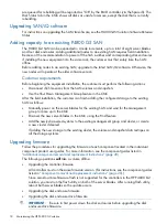
Repairing a storage system
For instructions on repairing a storage system, see the “Repairing a Storage System” and the
“Powering Off the Storage System” sections in the HP P4000 SAN Solution User Guide.
RAID 10 disk replacement and rebuild behavior
The RAID 10 configuration includes a single hot spare in bay 35.
When a disk is removed or fails in a RAID 10 configuration, the hot spare automatically begins
rebuilding. When the failed disk is replaced, the replacement disk begins rebuilding rather than
becoming the hot spare. At that time, the disk in bay 35 transitions back to being a hot spare. This
means that a simple disk replacement involves two rebuilds.
If more than one disk fails or is removed, the hot spare begins rebuilding one of the failed or
removed disks. When the multiple failed disks are replaced, the P700 controller attempts to restore
the disk in bay 35 as a hot spare, but it can only rebuild a single disk at a time. Any disks that
Repairing a storage system
17
Содержание P4800 G2
Страница 4: ...Battery replacement notices 46 Glossary 50 Index 51 4 Contents ...
Страница 40: ...German laser notice Italian laser notice Japanese laser notice 40 Regulatory compliance notices ...
Страница 47: ...French battery notice German battery notice Battery replacement notices 47 ...
Страница 48: ...Italian battery notice Japanese battery notice 48 Regulatory compliance notices ...
Страница 49: ...Spanish battery notice Battery replacement notices 49 ...

