HP Omen series Скачать руководство пользователя страница 61

2.

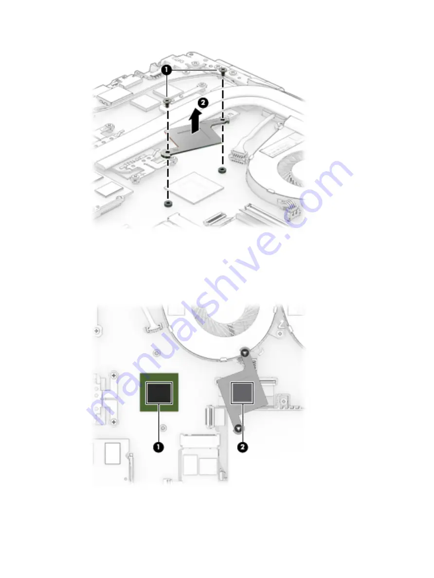
The following illustration shows the replacement thermal material locations. The thermal material must 
be thoroughly cleaned from the surfaces of the heat sink and the system board components each time 
the heat sink is removed. Replacement thermal material is included with the heat sink and system board 
spare part kits.

Thermal paste is used on the system board components (1) and on the heat sink areas (2) that service 
them.

Reverse this procedure to install the heat sink for CPU and graphics.

Component replacement procedures

51

Содержание Omen series

Страница 1: ...OMEN by HP Laptop PC Maintenance and Service Guide IMPORTANT This document is intended for HP authorized service providers only ...

Страница 2: ...t all features are available in all editions or versions of Windows Systems may require upgraded and or separately purchased hardware drivers software or BIOS update to take full advantage of Windows functionality Windows 10 is automatically updated which is always enabled ISP fees may apply and additional requirements may apply over time for updates Go to http www microsoft com for details The in...

Страница 3: ... another hard surface such as an adjoining optional printer or a soft surface such as pillows or rugs or clothing to block airflow Also do not allow the AC adapter to contact the skin or a soft surface such as pillows or rugs or clothing during operation The device and the AC adapter comply with the user accessible surface temperature limits defined by the International Standard for Safety of Info...

Страница 4: ...iv Safety warning notice ...

Страница 5: ...ion of Windows running with the processor or chipsets used in this system has limited support from Microsoft For more information about Microsoft s support please see Microsoft s Support Lifecycle FAQ at https support microsoft com lifecycle v ...

Страница 6: ...vi Processor information ...

Страница 7: ...ssembly subcomponents 24 Miscellaneous parts 25 4 Removal and replacement procedures preliminary requirements 27 Tools required 27 Service considerations 27 Plastic parts 27 Cables and connectors 28 Drive handling 28 Grounding guidelines 29 Electrostatic discharge damage 29 Packaging and transporting guidelines 30 Workstation guidelines 30 Equipment guidelines 31 5 Removal and replacement procedur...

Страница 8: ...IOS version 67 Downloading a BIOS update 68 7 Using HP PC Hardware Diagnostics UEFI 69 Downloading HP PC Hardware Diagnostics UEFI to a USB device 69 8 Backing up restoring and recovering 71 Creating recovery media and backups 71 Creating HP Recovery media select products only 71 Using Windows tools 72 Restore and recovery 73 Recovering using HP Recovery Manager 73 What you need to know before you...

Страница 9: ...cifications 77 39 62 cm 15 6 in display specifications 78 Hard drive specifications 78 10 Power cord set requirements 80 Requirements for all countries 80 Requirements for specific countries and regions 81 11 Recycling 83 Index 84 ix ...

Страница 10: ...x ...

Страница 11: ...esign Power cTDP 35 W 6th generation Intel Core i5 Processor Intel Core i5 6300 HQ 2 3 GHz turbo up to 3 2 GHz 2133 MHz 6 MB L3 Quad TDP 45 W cTDP 35 W 6th generation Intel Core i3 Processor Intel Core i3 6100H 2 7 GHz turbo up to 2 7 GHz 2133 MHz 3 MB L3 Dual TDP 35 W 7th generation Intel Core i7 Processor Intel Core i7 7700HQ 2 8 GHz turbo up to 3 8 GHz 2400 MHz 6 MB L3 Quad TDP 45 W cTDP 35 W 7...

Страница 12: ... up to 4096 MB of dedicated video memory 256 Mx32 GDDR5 x 4 PCs 128 bit not available to Core i3 NVIDIA GeForce GTX 965M with up to 4096 MB of dedicated video memory 256 Mx32 GDDR5 x 4 PCs 128 bit not available to Core i3 AMD RadeonTM RX 460 R16M G1 70 with up to 4096 MB of dedicated video memory 256Mx32 GDDR5 x 4 PCs limited to China localization only Internal graphics Intel HD Graphics 630 Hybri...

Страница 13: ...0 nits FHD WLED AntiGlare 1920x1080 slim flat 3 2 mm UWVA eDP typical brightness 250 nits bridged to 220 nits Ultra High Definition UHD Pentile WLED AntiGlare 3840x2160 ultra slim flat 2 6 mm UWVA eDP typical brightness 300 nits Color Back cover Shadow Mesh Pattern Shadow Mesh Twinkle Black limited to China localization non 3D camera and NVIDIA GeForce GTX 960M 2GB VRAM Core i5 NVIDIA GeForce GTX ...

Страница 14: ...e i7 or China localization non 3D camera and NVIDIA GeForce GTX 1050 2GB VRAM Core i5 NVIDIA GeForce GTX 1050 2 GB VRAM Core i7 NVIDIA GeForce GTX 1050Ti 2GB VRAM Core i5 NVIDIA GeForce GTX 1050Ti 2 GB VRAM Core i7 Base enclosure Twinkle Black Memory Two SODIMM slots customer non accessible non upgradeable DDR4 2133 Dual Channel Support DDR4 2400 bridge to DDR4 2133 DDR4 2400 Dual Channel Support ...

Страница 15: ...GB 512 GB Hard drive SSD configurations 1 TB 7200 9 5 mm hard drive 512 GB PCIe Non Volatile Memory Express NVMe Triple Level Cell TLC M 2 SSD 1 TB 7200 9 5 mm hard drive 256 GB PCIe NVMe TLC M 2 SSD 1 TB 7200 9 5 mm hard drive 128 GB M 2 SATA 3 SSD Value 2 TB 5400 9 5 mm hard drive 128 GB M 2 SATA 3 SSD Value Optical drive External USB 9 5 mm tray load SATA External USB ODD Aluminum material DVD ...

Страница 16: ...rnet Integrated 10 100 1000 NIC Wireless Integrated Wireless options with dual antennas M 2 PCIe Intel Dual Band Wireless AC 7265 802 11 ac 2x2 WiFi Bluetooth 4 2 Combo Adapter non vPRO Intel WiDi support select products only Compatible with Miracast certified devices External media cards HP Multi Format Digital Media Card Reader Supports SD SDHC SDXC Push Push Insertion Removal Internal card expa...

Страница 17: ... pointing devices Full Size Backlit 3 Coat paint island style keyboard with numeric key pad TouchPad Requirements Clickpad with image sensor Multitouch gestures enabled Support Modern Trackpad Gestures Taps enabled as default Power requirement Batteries Battery life enhancement Supports battery fast charge when the battery charge remaining is between zero and 90 the battery will charge to 90 of fu...

Страница 18: ...with 4 GB or any processor with 1080p screen and 8GB For Emerging Market EM SL Windows 10 Home EM SL Windows 10 Home High End EM SL for use with Intel Core i7 processors with 4 GB or any processor with 1080p screen and 8GB CPPP Windows 10 Home China Language Edition CPPP Windows 10 Home High End China Language Edition for use with Intel Core i7 processors with 4 GB or any processor with 1080p scre...

Страница 19: ... temporarily parked the hard drive select products only 3 USB 3 0 port Connects an optional USB device such as a keyboard mouse external drive printer scanner or USB hub 4 HDMI port Connects an optional video or audio device such as a high definition television any compatible digital or audio component or a high speed High Definition Multimedia Interface HDMI device 5 RJ 45 network jack status lig...

Страница 20: ... or USB hub 4 Audio out headphone Audio in microphone combo jack Connects optional powered stereo speakers headphones earbuds a headset or a television audio cable Also connects an optional headset microphone This jack does not support optional standalone microphones WARNING To reduce the risk of personal injury adjust the volume before putting on headphones earbuds or a headset For additional saf...

Страница 21: ...roducts type Intel RealSense in the taskbar search box to explore additional features demos and apps 4 WLAN antennas Send and receive wireless signals to communicate with wireless local area networks WLANs The antennas are not visible from the outside of the computer For optimal transmission keep the areas immediately around the antennas free from obstructions For wireless regulatory notices see t...

Страница 22: ...inger gestures to move the pointer or activate items on the screen 2 Left TouchPad button Functions like the left button on an external mouse 3 Right TouchPad button Functions like the right button on an external mouse 12 Chapter 2 External component identification ...

Страница 23: ...ter shuts off power to the display and other unneeded components Off The computer is off or in Hibernation Hibernation is a power saving state that uses the least amount of power 2 Caps lock light On Caps lock is on which switches the key input to all capital letters 3 Mute light Amber Computer sound is off Off Computer sound is on Top 13 ...

Страница 24: ...bernation CAUTION Pressing and holding down the power button results in the loss of unsaved information If the computer has stopped responding and shutdown procedures are ineffective press and hold the power button down for at least 5 seconds to turn off the computer To learn more about your power settings see your power options Type power in the taskbar search box and then select Power and sleep ...

Страница 25: ...ng the action keys An action key performs an assigned function The icon on each action key illustrates the function for that key To use an action key press and hold the key Icon Description Decreases the screen brightness incrementally as long as you hold down the key Increases the screen brightness incrementally as long as you hold down the key Switches the screen image between display devices co...

Страница 26: ...revious section of a DVD or a Blu ray Disc BD Starts pauses or resumes playback of an audio CD a DVD or a BD Plays the next track of an audio CD or the next section of a DVD or a BD Turns the airplane mode and wireless feature on or off NOTE The airplane mode key is also referred to as the wireless button NOTE A wireless network must be set up before a wireless connection is possible 16 Chapter 2 ...

Страница 27: ...Enable airflow to cool internal components NOTE The computer fan starts up automatically to cool internal components and prevent overheating It is normal for the internal fan to cycle on and off during routine operation Bottom 17 ...

Страница 28: ...d in this section the bottom of the computer inside the battery bay under the service door or on the back of the display Service label Provides important information to identify your computer When contacting support you will probably be asked for the serial number and possibly for the product number or the model number Locate these numbers before you contact support Your service label will resembl...

Страница 29: ...rranty period Regulatory label s Provide s regulatory information about the computer Wireless certification label s Provide s information about optional wireless devices and the approval markings for the countries or regions in which the devices have been approved for use Labels 19 ...

Страница 30: ...rted parts for your computer go to http partsurfer hp com select your country or region and then follow the on screen instructions NOTE Details about your computer including model serial number product key and length of warranty are on the service tag at the bottom of your computer See Labels on page 18 for details 20 Chapter 3 Illustrated parts catalog ...

Страница 31: ...over with TouchPad and keyboard see TouchPad on page 58 for a detailed list of country codes 3 TouchPad board For use with products with Shadow Mesh 860364 001 For use with products with Hybrid Green 860330 001 TouchPad cable 858967 001 4 Speaker Kit 858976 001 Computer major components 21 ...

Страница 32: ...005 For use with products with Intel 7th generation processors 2 GB 2400 MHz 1 2v DDR4 shared 864271 855 4 GB 2400 MHz 1 2v DDR4 shared 862397 855 8 GB 2400 MHz 1 2v DDR4 shared 862398 855 12 WLAN module Intel Dual Band Wireless AC 7265 793840 005 13 Heat sink Products with NVIDIA GeForce GTX 950M 960M 965M hybrid graphics 856668 001 Products with AMD Radeon hybrid graphics 901922 001 Products wit...

Страница 33: ...neration processors with AMD Radeon hybrid graphics 849910 850 4 cell polymer battery 63 3 Whr 4175 mAh for use with products with Intel 7th generation processors not supported with AMD Radeon hybrid graphics 905277 855 21 Base enclosure Twinkle Black for Shadow Mesh finish 858965 001 Twinkle Black for Hybrid Green finish 905114 001 Computer major components 23 ...

Страница 34: ... with an HD camera 856725 001 For products with a 3D camera 856726 001 2 Camera Intel RealSense 3D camera 1080p 781624 005 HP Wide Vision HD camera 1720p 846006 003 3D camera cable 859445 001 3 Raw panel 15 6 panel FHD AG UWVA slim flat 752920 014 24 Chapter 3 Illustrated parts catalog ...

Страница 35: ...with antenna for products with a 3D camera 856718 001 Miscellaneous parts Component Spare part number AC adapter 120 W adapter PFC S 3P slim 4 5 mm for use products with Intel 6th generation processors 710415 001 150 W adapter PFC smart slim 4 5 mm for use with products with Intel 6th generation processors and GeForce GTX 965M products with Intel 6th generation processors and Radeon RX 460 or prod...

Страница 36: ...in the People s Republic of China 286497 008 For use in South Africa 361240 002 For use in Switzerland 213354 008 For use in Taiwan 393313 003 For use in Thailand 285096 006 For use in the United Kingdom 213351 008 Screw Kit 856752 001 26 Chapter 3 Illustrated parts catalog ...

Страница 37: ...e considerations The following sections include some of the considerations that you must keep in mind during disassembly and assembly procedures NOTE As you remove each subassembly from the computer place the subassembly and all accompanying screws away from the work area to prevent damage Plastic parts CAUTION Using excessive force during disassembly and reassembly can damage plastic parts Use ca...

Страница 38: ...or inserting a hard drive shut down the computer If you are unsure whether the computer is off or in Hibernation turn the computer on and then shut it down through the operating system Before handling a drive be sure that you are discharged of static electricity While handling a drive avoid touching the connector Before removing an optical drive be sure that a disc is not in the drive and be sure ...

Страница 39: ... these precautions Keep components in their electrostatic safe containers until you are ready to install them Before touching an electronic component discharge static electricity by using the guidelines described in this section Avoid touching pins leads and circuitry Handle electronic components as little as possible If you remove a component place it in an electrostatic safe container The follow...

Страница 40: ... materials are selected to avoid static charging When grounding is not possible use an ionizer to dissipate electric charges Workstation guidelines Follow these grounding workstation guidelines Cover the workstation with approved static shielding material Use a wrist strap connected to a properly grounded work surface and use properly grounded tools and equipment Use conductive field service tools...

Страница 41: ...istance between the operator and ground To be effective the conductive equipment must be worn in contact with the skin The following grounding equipment is recommended to prevent electrostatic damage Antistatic tape Antistatic smocks aprons and sleeve protectors Conductive bins and other assembly or soldering aids Nonconductive foam Conductive tabletop workstations with ground cords of one megohm ...

Страница 42: ...pported parts for your computer go to http partsurfer hp com select your country or region and then follow the on screen instructions There are as many as 61 screws that must be removed replaced and or loosened when servicing the parts described in this chapter Make special note of each screw size and location during removal and replacement Base enclosure Description Spare part number Twinkle Blac...

Страница 43: ...lly disengage those clips as you are removing the base enclosure 3 Slide a nylon flake tool around the edge of the base enclosure to loosen it taking care not to damage the internal clips Lift the front edge 1 to access the internal clips in the battery area 4 Remove the base enclosure 2 Reverse this procedure to replace the base enclosure Component replacement procedures 33 ...

Страница 44: ... a compatible battery purchased from HP CAUTION Removing a user replaceable battery that is the sole power source for the computer can cause loss of information To prevent loss of information save your work or shut down the computer through Windows before removing the battery Before removing the battery follow these steps 1 Shut down the computer 2 Disconnect all external devices connected to the ...

Страница 45: ...2 Disconnect the battery cable from the system board 1 release the battery cable from the routing channels 2 and then lift the battery cable to remove it 3 Component replacement procedures 35 ...

Страница 46: ...x5 screws 1 lift the battery 2 and then slide the battery 3 to remove it from the computer Reverse this procedure to replace the battery 36 Chapter 5 Removal and replacement procedures for authorized service provider parts ...

Страница 47: ...ect the power from the computer by first unplugging the power cord from the AC outlet and then unplugging the AC adapter from the computer 4 Remove the base enclosure see Base enclosure on page 32 5 Disconnect the battery see Battery on page 34 Remove the display assembly 1 Remove 3 Phillips 2 5x6 0 screws from the left hinge and 3 Phillips 2 5x6 0 screws from the right hinge bracket 1 and then li...

Страница 48: ... routing channels 4 3 Rotate the display assembly 1 and then remove the display assembly 2 from the base enclosure NOTE For display panel and display component removal procedures see Display panel on page 60 Reverse this procedure to install the display assembly 38 Chapter 5 Removal and replacement procedures for authorized service provider parts ...

Страница 49: ...w these steps 1 Shut down the computer 2 Disconnect all external devices connected to the computer 3 Disconnect the power from the computer by first unplugging the power cord from the AC outlet and then unplugging the AC adapter from the computer 4 Remove the base enclosure see Base enclosure on page 32 5 Disconnect the battery see Battery on page 34 Remove the hard drive 1 Disconnect the hard dri...

Страница 50: ...essary to disassemble the hard drive follow these steps Remove the hard drive connector 1 and then remove the side brackets 2 Reverse this procedure to reassemble the hard drive 40 Chapter 5 Removal and replacement procedures for authorized service provider parts ...

Страница 51: ... in Hibernation turn the computer on and then shut it down through the operating system 2 Disconnect the power from the computer by unplugging the power cord from the computer 3 Disconnect all external devices from the computer 4 Remove the base enclosure see Base enclosure on page 32 5 Disconnect the battery see Battery on page 34 Remove the SSD 1 Remove the Phillips M2 0 x 2 5 screw 1 that secur...

Страница 52: ...he latest BIOS CAUTION Failure to update the computer to the latest BIOS prior to installing new memory may result in various system problems To update BIOS 1 Navigate to http www hp com 2 Select Support Support drivers 3 In the Enter my HP model number box type the computer model information and then select Find my product or Select Identify now 4 Select the link for the computer model 5 Select t...

Страница 53: ...side of the memory module The memory module tilts up 3 Grasp the edge of the memory module 2 and then gently pull the memory module out of the memory module slot CAUTION To prevent damage to the memory module hold the memory module by the edges only Do not touch the components on the memory module To protect a memory module after removal place it in an electrostatic safe container Reverse this pro...

Страница 54: ...the power cord from the AC outlet and then unplugging the AC adapter from the computer 4 Remove the base enclosure see Base enclosure on page 32 5 Disconnect the battery see Battery on page 34 Remove the WLAN module 1 Carefully disconnect 2 antenna cables 1 2 Remove 1 Phillips 2 0x2 5 screw 2 and then remove the WLAN module 3 NOTE If the WLAN antenna cables are not connected to the terminals on th...

Страница 55: ...ices connected to the computer 3 Disconnect the power from the computer by first unplugging the power cord from the AC outlet and then unplugging the AC adapter from the computer 4 Remove the base enclosure see Base enclosure on page 32 5 Disconnect the battery see Battery on page 34 Remove the USB board Disconnect the zero insertion force ZIF connector 1 remove the USB board cable 2 disconnect 2 ...

Страница 56: ...mputer 3 Disconnect the power from the computer by first unplugging the power cord from the AC outlet and then unplugging the AC adapter from the computer 4 Remove the base enclosure see Base enclosure on page 32 5 Disconnect the battery see Battery on page 34 and then remove the following components a Display assembly see Display assembly on page 37 b Hard drive see Hard drive on page 39 c USB bo...

Страница 57: ...2 Lift the power button board 2 at an angle and then remove the board 3 Reverse this procedure to install the power button board Component replacement procedures 47 ...

Страница 58: ...ower from the computer by first unplugging the power cord from the AC outlet and then unplugging the AC adapter from the computer 4 Remove the base enclosure see Base enclosure on page 32 5 Disconnect the battery see Battery on page 34 Remove the fans 1 Disconnect the fan cables 1 and then release the cable from the threading channels 2 2 Remove the 4 Phillips 2x5 screws 3 from the fans lift and r...

Страница 59: ...omputer If you are unsure whether the computer is off or in Hibernation turn the computer on and then shut it down through the operating system 2 Disconnect the power from the computer by unplugging the power cord from the computer 3 Disconnect all external devices from the computer 4 Remove the base enclosure see Base enclosure on page 32 5 Disconnect the battery see Battery on page 34 Remove the...

Страница 60: ...are part number Heat sink for CPU and graphics 725625 001 Before removing the heat sink for CPU and graphics follow these steps 1 Turn off the computer If you are unsure whether the computer is off or in Hibernation turn the computer on and then shut it down through the operating system 2 Disconnect the power from the computer by unplugging the power cord from the computer 3 Disconnect all externa...

Страница 61: ...d the system board components each time the heat sink is removed Replacement thermal material is included with the heat sink and system board spare part kits Thermal paste is used on the system board components 1 and on the heat sink areas 2 that service them Reverse this procedure to install the heat sink for CPU and graphics Component replacement procedures 51 ...

Страница 62: ...he power cord from the AC outlet and then unplugging the AC adapter from the computer 4 Remove the base enclosure see Base enclosure on page 32 5 Disconnect the battery see Battery on page 34 and then remove the following components a Fans see Fans on page 48 b Heatsink see Heat sink for hybrid graphics memory on page 49 Remove the speakers 1 Disconnect the right speaker cable 1 2 Lift the left sp...

Страница 63: ... 863097 xxx Intel i5 6300HQ system board Radeon RX 460 4 GB 863098 xxx Intel 7th generation processors Intel i7 7700HQ system board GeForce GTX 1050 2 GB 914770 xxx Intel i5 7300HQ system board GeForce GTX 1050 2 GB 914771 xxx Intel i7 7700HQ system board GeForce GTX 1050 4 GB 914772 xxx Intel i5 7300HQ system board GeForce GTX 1050 4 GB 914773 xxx Intel i7 7700HQ system board Radeon RX 460 4 GB 9...

Страница 64: ... Heat sink for hybrid graphics see Heat sink for hybrid graphics memory on page 49 Heat sink for CPU and graphics see Heat sink for CPU and graphics on page 50 WLAN module see WLAN module on page 44 Memory module see Memory on page 42 RTC battery see RTC battery on page 55 Remove the system board 1 Disconnect the following cables and zero insertion force ZIF connectors from the system board Wirele...

Страница 65: ...n the computer 2 Disconnect all external devices connected to the computer 3 Disconnect the power from the computer by first unplugging the power cord from the AC outlet and then unplugging the AC adapter from the computer 4 Remove the base enclosure see Base enclosure on page 32 5 Remove the battery see Battery on page 34 and then remove the following components a Hard drive see Hard drive on pag...

Страница 66: ...low these steps 1 Shut down the computer 2 Disconnect all external devices connected to the computer 3 Disconnect the power from the computer by first unplugging the power cord from the AC outlet and then unplugging the AC adapter from the computer 4 Remove the base enclosure see Base enclosure on page 32 5 Remove the battery see Battery on page 34 and then remove the following components a Hard d...

Страница 67: ...er connector 1 Carefully place the system board face down 2 Disconnect the connector cable and then remove the power connector Reverse this procedure to install the power connector Component replacement procedures 57 ...

Страница 68: ...B31 Thailand 281 France 051 Portugal 131 Turkey 141 Germany 041 Romania 271 United Kingdom 031 Greece 151 Russia 251 United States 001 Hungary 211 Saudi Arabia 171 India 002 Slovenia BA1 IMPORTANT Make special note of each screw and screw lock size and location during removal and replacement Before removing the TouchPad follow these steps 1 Shut down the computer 2 Disconnect all external devices ...

Страница 69: ...hPad cable 1 3 Remove the 3 Phillips 2 0x2 5 screws 2 4 Lift the front of the TouchPad 3 and then slide the TouchPad 4 forward to remove it Reverse this procedure to install the TouchPad Component replacement procedures 59 ...

Страница 70: ...6715 001 In Shadow Mesh finish with antenna for products with 3D camera 856718 001 IMPORTANT Make special note of each screw and screw lock size and location during removal and replacement Before removing the display assembly follow these steps 1 Shut down the computer 2 Disconnect all external devices connected to the computer 3 Disconnect the power from the computer by first unplugging the power...

Страница 71: ...the display bezel and before removing the display panel See Camera on page 65 2 If it is necessary to replace the display panel remove 4 Phillips 2 0x2 5 screws from the display panel 1 and then lift the display panel 2 to remove it Component replacement procedures 61 ...

Страница 72: ...ecessary to replace the hinge brackets remove the Phillips 2 5x6 0 screw from the top of each hinge bracket 1 and the 3 Phillips 2 5x6 0 screws from each hinge 2 remove the hinge brackets from the back cover 3 and then lift the hinge brackets 4 to remove them 62 Chapter 5 Removal and replacement procedures for authorized service provider parts ...

Страница 73: ...x2 0 screw from each hinge bracket 1 and then separate the hinge caps 2 from the hinge brackets 6 Remove the Phillips 2 0x2 0 screw from each hinge 1 and then lift the hinges 2 to remove them Component replacement procedures 63 ...

Страница 74: ...rom the back cover release the WLAN cable from the routing channels 2 and then lift the antennas and cable to remove them 3 Reverse this procedure to install the display assembly and components 64 Chapter 5 Removal and replacement procedures for authorized service provider parts ...

Страница 75: ...vices connected to the computer 3 Disconnect the power from the computer by first unplugging the power cord from the AC outlet and then unplugging the AC adapter from the computer 4 Remove the base enclosure see Base enclosure on page 32 5 Disconnect the battery see Battery on page 34 and then remove the following components a Display assembly see Display assembly on page 37 b Display bezel see Di...

Страница 76: ...crophone board select products only disconnect the cable 1 and then lift the microphone board 2 to remove it Reverse this procedure to install the camera 66 Chapter 5 Removal and replacement procedures for authorized service provider parts ...

Страница 77: ...e on the HP website Most BIOS updates on the HP website are packaged in compressed files called SoftPaqs Some download packages contain a file named Readme txt which contains information regarding installing and troubleshooting the file Determining the BIOS version To decide whether you need to update Setup Utility BIOS first determine the BIOS version on your computer To reveal the BIOS version i...

Страница 78: ...y the most recent BIOS update and compare it to the BIOS version currently installed on your computer If the update is more recent than your BIOS version make a note of the date name or other identifier You may need this information to locate the update later after it has been downloaded to your hard drive b Follow the on screen instructions to download your selection to the hard drive Make a note...

Страница 79: ...lowing order a Connected USB drive NOTE To download the HP PC Hardware Diagnostics UEFI tool to a USB drive see Downloading HP PC Hardware Diagnostics UEFI to a USB device on page 69 b Hard drive c BIOS 3 When the diagnostic tool opens select the type of diagnostic test you want to run and then follow the on screen instructions NOTE If you need to stop a diagnostic test press esc Downloading HP PC...

Страница 80: ...let HP automatically detect your product 4 Select your computer and then select your operating system 5 In the Diagnostic section follow the on screen instructions to select and download the UEFI version you want 70 Chapter 7 Using HP PC Hardware Diagnostics UEFI ...

Страница 81: ... the HP Recovery partition on the computer The backup can be used to reinstall the original operating system in cases where the hard drive is corrupted or has been replaced For information on creating recovery media see Creating HP Recovery media select products only on page 71 For information on the recovery options that are available using the recovery media see Using Windows tools on page 72 Us...

Страница 82: ...rately to create recovery discs If you use an external optical drive it must be connected directly to a USB port on the computer the drive cannot be connected to a USB port on an external device such as a USB hub If you cannot create DVD media yourself you can obtain recovery discs for your computer from HP See the Worldwide Telephone Numbers booklet included with the computer You can also find co...

Страница 83: ...o remove the recovery partition to reclaim hard drive space HP Recovery Manager offers the Remove Recovery Partition option For more information see Removing the HP Recovery partition select products only on page 76 Recovering using HP Recovery Manager HP Recovery Manager software allows you to recover the computer to its original factory state by using the HP Recovery media that you either create...

Страница 84: ...rking To start HP Recovery Manager from the HP Recovery partition IMPORTANT For a tablet with a detachable keyboard connect the keyboard to the keyboard dock before beginning these steps select products only 1 Type recovery in the taskbar search box select Recovery Manager and then select HP Recovery Environment or For computers or tablets with keyboards attached press f11 while the computer boots...

Страница 85: ...to the keyboard dock before beginning these steps 1 Insert the HP Recovery media 2 Access BIOS For computers or tablets with keyboards attached Turn on or restart the computer or tablet quickly press esc and then press f9 for boot options For tablets without keyboards Turn on or restart the tablet and then quickly hold down the volume down button then select f9 or Turn on or restart the tablet and...

Страница 86: ...overy partition So before you remove the Recovery partition create HP Recovery media see Creating HP Recovery media select products only on page 71 NOTE The Remove Recovery Partition option is only available on products that support this function Follow these steps to remove the HP Recovery partition 1 Type recovery in the taskbar search box and then select HP Recovery Manager 2 Select Remove Reco...

Страница 87: ...5 A 120 W 19 5 V dc 7 70 A 150 W Temperature Operating 5 C to 35 C 41 F to 95 F Nonoperating 20 C to 60 C 4 F to 140 F Relative humidity noncondensing Operating 10 to 90 Nonoperating 5 to 95 Maximum altitude unpressurized Operating 15 m to 3 048 m 50 ft to 10 000 ft Nonoperating 15 m to 12 192 m 50 ft to 40 000 ft NOTE Applicable product safety standards specify thermal limits for plastic surfaces...

Страница 88: ...r consumption 2 0 W Viewing angle 65 horizontal 50 vertical typical Hard drive specifications 1 TB 2TB Dimensions Height 9 5 mm 9 5 mm Width 69 85 mm 69 85 mm Weight 102 g max 130 g max Interface type SATA 3 0 SATA 3 0 Transfer rate 600 MB sec 600 MB sec Security ATA 8 security ATA 8 security Seek times typical read including setting Single track 2 ms 2 ms Average 13 0 ms 12 0 ms Maximum 15 0 ms 2...

Страница 89: ...rs to hard drive storage capacity Actual accessible capacity is less Actual drive specifications may differ slightly NOTE Certain restrictions and exclusions apply Contact support for details Hard drive specifications 79 ...

Страница 90: ...rements are applicable to all countries and regions The length of the power cord set must be at least 1 0 m 3 3 ft and no more than 2 0 m 6 5 ft All power cord sets must be approved by an acceptable accredited agency responsible for evaluation in the country or region where the power cord set will be used The power cord sets must have a minimum current capacity of 10 A and a nominal voltage rating...

Страница 91: ... KTL 5 Sweden SEMKO 1 Switzerland SEV 1 Taiwan BSMI 6 Thailand TISI 1 The United Kingdom ASTA 1 The United States UL 2 1 The flexible cord must be Type HO5VV F 3 conductor 0 75 mm conductor size Power cord set fittings appliance coupler and wall plug must bear the certification mark of the agency responsible for evaluation in the country or region where it will be used 2 The flexible cord must be ...

Страница 92: ...r the CCC certification mark 5 The flexible cord must be Type H05VV F 3 conductor 0 75 mm conductor size KTL logo and individual approval number must be on each element Corset approval number and logo must be printed on a flag label 6 The flexible cord must be Type HVCTF 3 conductor 1 25 mm conductor size Power cord set fittings appliance coupler cable and wall plug must bear the BSMI certificatio...

Страница 93: ...he battery in general household waste Follow the local laws and regulations in your area for battery disposal HP encourages customers to recycle used electronic hardware HP original print cartridges and rechargeable batteries For more information about recycling programs see the HP Web site at http www hp com recycle 83 ...

Страница 94: ...uter specifications 77 connector power 9 D display specifications 78 display assembly removal 37 60 spare part numbers 37 60 subcomponents 24 display cable spare part number 25 60 Display panel spare part numbers 21 display panel product description 3 spare part number 60 drive light 9 E esc key identifying 15 Ethernet product description 6 F fan spare part number 22 fans removal 48 spare part num...

Страница 95: ...56 power connector identifying 9 power cord requirements for all countries 80 requirements for specific countries and regions 81 set requirements 80 spare part numbers 25 power lights identifying 13 power requirements product description 7 processor product description 1 product description audio 6 camera 5 chipset 1 color 3 display panel 3 Ethernet 6 external media cards 6 graphics 1 hard drive 5...

Страница 96: ... spare part numbers 21 TouchPad buttons 12 removal 58 spare part numbers 21 58 TouchPad board spare part numbers 21 TouchPad zone identifying 12 traveling with the computer 19 U USB 2 0 port identifying 10 USB 3 0 port 9 USB 3 0 port identifying 10 USB board removal 45 spare part number 22 spare part numbers 45 USB board cable spare part number 22 USB ports identifying 9 V vents identifying 17 18 ...

Отзывы: