HP OMEN 25 Скачать руководство пользователя страница 18

14 


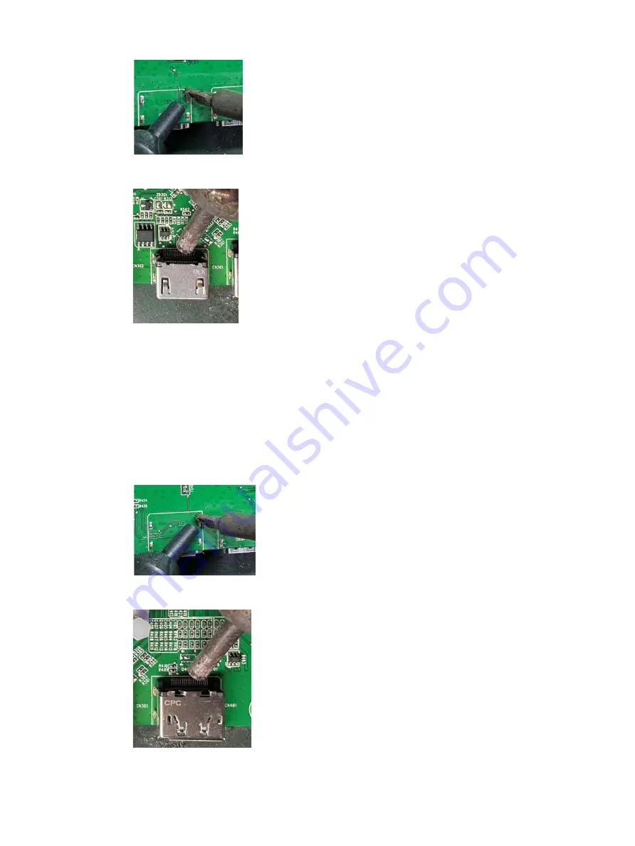
HDMI connector repairing 

2)


Use a hot air gun to melt the solder on the pins.


HDMI connector repairing 

3)


Lift the CN301, CN302 connector from the PCB. 

4)


Place the new component on the PCB. Be sure that it matches the PCB footprint. 

5)


Solder the new component. 

DP connector CN401 

Repair the DP connector: 

1)


Use a soldering iron and a desoldering pump to remove as much solder as possible from the pin. 


DP connector repairing 

2)


Use a hot air gun to melt the solder on the pins. 


DP connector repairing 

3)


Lift the CN401 connector from the PCB. 

Содержание OMEN 25

Страница 1: ...Maintenance and Service Guide OMEN by HP 25 model SUMMARY This guide provides information about spare parts removal and replacement of parts diagnostic tests problem troubleshooting and more ...

Страница 2: ...ates and other countries The information contained herein is subject to change without notice The only warranties for HP products and services are set forth in the express warranty statements accompanying such products and services Nothing herein should be construed as constituting an additional warranty HP shall not be liable for technical or editorial errors or omissions contained herein First E...

Страница 3: ... Side and bottom components on the rear panel 4 Stand components 5 Locating the rating label 6 3 Illustrated parts catalog 7 How to order parts 8 4 Removal and replacement procedures 9 Preparation for disassembly 9 RC 9 Connector repair 11 HDMI connector CN301 CN302 13 DP connector CN401 14 DC jack connector CN801 15 USB upstream connector CN701 15 USB connector CN702 CN703 15 Headphone connector ...

Страница 4: ......

Страница 5: ...opening the product s cabinet Modules containing electrical components are sensitive to electrostatic discharge ESD Follow ESD safety procedures while handling these parts Some products contain more than one battery Do not disassemble or expose a battery to high temperatures such as throwing into fire or the battery may explode Refer to government requirements for battery recycling or disposal Thi...

Страница 6: ...tance in Electrical and Electronic Equipment Directive is a legal requirement by the EU European Union for the global electronics industry sold in the EU and other countries Any electrical and electronics products launched in the market after June 2006 should meet this RoHS requirement Products launched in the market before June 2006 are not required to be compliant with RoHS parts If the original...

Страница 7: ... on monitor stand Plug and Play capability if supported by your operating system On screen display OSD adjustments in 10 languages for easy setup and screen optimization My Display software for adjusting monitor settings through Windows HDCP High bandwidth Digital Content Protection used on digital inputs In select regions software and documentation optical disc provided with the monitor that incl...

Страница 8: ...ion buttons Use these buttons to navigate through the OSD menu based on the indicators above the buttons that are activated when the OSD menu is open 4 Security cable slot Connects a security cable from the monitor to a stationary object 5 USB 3 x 2 downstream Connect optional USB devices to the monitor 6 USB 3 x upstream Connects the USB hub cable from the source device to the monitor 7 Power con...

Страница 9: ...on the rear of the monitor use this illustration and table Rear of the monitor showing of stand components Table 1 2 Rear components and their descriptions Component Function 1 Stand release button 2 Headphone storage hook Connects headphone 3 Cable management ...

Страница 10: ...n contacting HP about the monitor model The rating label is located on the bottom of the display head Label location For worldwide models except India Barcode label For worldwide models except India Barcode label for Worldwide region For India Barcode label for India region Spec label For worldwide region Spec label for Worldwide region ...

Страница 11: ...5 ZN 4 4 SCREW P CROSS M3 6 ZN CC 4 5 PCBA IF B W OSP LP25Q3 71L OMEN by HP 25 1 6 SCREW I CROSS M4 6 BLK Zn HF NYLOK nbs 4 7 ASSY CHASSIS OMEN HF 1 8 ASSY STAND HINGE OMEN HF 1 9 REAR COVER OMEN HF 1 10 REAR VOODOO LOGO OMEN HF 4 11 REAR OMEN LOGO OMEN HF 1 12 ASSY ARM OF STAND OMEN HF 4 13 ASSY WALL MOUNT OMEN HF 1 14 CABLE MANAGEMENT OF ARM OMEN HF 1 15 ASSY BASE OF STAND OMEN HF 1 16 KEY BUTTO...

Страница 12: ... 208658 1051 Headphone CN101 Digi Key 54 00177 Notes the chassis and rear cover need to be modified to make the connector opening larger USB upstream CN701 Farnell 897 46 009 90 300000 USB A CN702 CN703 Farnell 48405 0003 Notes the chassis and rear cover need to be modified to make the connector opening larger DC jack CN801 Digi Key PJ 096H NOTE The connector may need to be modified to meet functi...

Страница 13: ...r of this guide 2 Clean the room for disassembly 3 Identify the disassembly area 4 Check the position that the monitors are to be placed along with the number of monitors Prepare the area for material flow according to the disassembly layout 5 Be sure to have the following equipment and materials Press fixture Working table Screwdriver Knife Gloves Cleaning cloth ESD protection Scraper bar in the ...

Страница 14: ...ntion to avoid the LVDS cable and Lightbar cable Monitor separate step 2 Unlock 4 screws and pull out the Audio board and Keypad cable then separated the chassis assy form the back cover assy PCBA and rear cover separate step 3 Unlock 2 screws fixed Keypad and Bucket then the keypad is separated ...

Страница 15: ...board and chassis then separate th PCBA and chassis separate step 5 Unlock 4 screws fixed the hinge and chassis take out the small mylar then separate the hinge Chassis screw separate step Connector repair This procedure includes HDMI DisplayPort DC jack headphone USB upstream and USB connectors ...

Страница 16: ...1 and USB side board board part number 790N40300 H0 The connectors identifiers are as follows Connector Location HDMI CN301 CN302 DisplayPort CN401 USB upstream CN701 USB CN702 CN703 DC jack CN801 Connector location showing of main board Connector Location Headphone CN101 ...

Страница 17: ...board Before repairing connectors follow these steps Prepare the monitor for disassembly See Preparation for disassembly on page 9 HDMI connector CN301 CN302 Repair the HDMI connector 1 Use a soldering iron and a desoldering pump to remove as much solder as possible from the pin ...

Страница 18: ... component on the PCB Be sure that it matches the PCB footprint 5 Solder the new component DP connector CN401 Repair the DP connector 1 Use a soldering iron and a desoldering pump to remove as much solder as possible from the pin DP connector repairing 2 Use a hot air gun to melt the solder on the pins DP connector repairing 3 Lift the CN401 connector from the PCB ...

Страница 19: ...new component USB upstream connector CN701 Repair the USB upstream connector 1 Use a hot air gun to melt the solder on the pins Pin solder with soldering iron and absorber You can gently push down with the soldering iron once everything is molten to move the CN602 out of the through holes USB upstream connector repairing 2 Lift the CN701 connector from the PCB 3 Place the new component on the PCB ...

Страница 20: ...ir be sure to confirm that all functions are working Table 4 1 Function test Te st item Operating description Tool used HDMI test Confirm whether image displays and sound plays correctly on the monitor Computer or DVD player DP test Confirm whether image displays and sound plays correctly on the monitor Computer or DVD player Audio test Change volume and balance to confirm whether volume is smooth...

Страница 21: ...in Sleep mode Press any key on the keyboard or move the mouse to exit Sleep mode Video card is incompatible Open the OSD menu and select the Input Control menu Set Auto Switch Input to Off and manually select the input Image appears blurred indistinct or too dark Brightness is too low Open the OSD menu and select Brightness to adjust the brightness scale as needed Check Video Cable is displayed on...

Страница 22: ...s are Locked is displayed The monitor s OSD lock function is enabled Press and hold the Menu button on the front bezel to 10 seconds to disable the OSD lockout function Power Button is Locked is Displayed The monitor s power button is locked Press and hold the power button for 10 seconds to disable the power button lock function ...

Страница 23: ...ard removal 15 power button location 5 power connector location 6 power light location 5 precautions 1 preparation for disassembly 12 RC removal 12 rear components 6 removal power board 15 RC 12 xxxx 20 removal and replacement procedures 12 returning to customer 2 RoHS 2002 95 EC requirements 2 safety information 1 serial number location 7 service information 1 spare parts 9 support and troublesho...

Страница 24: ...20 ...

Отзывы: