background image

3.

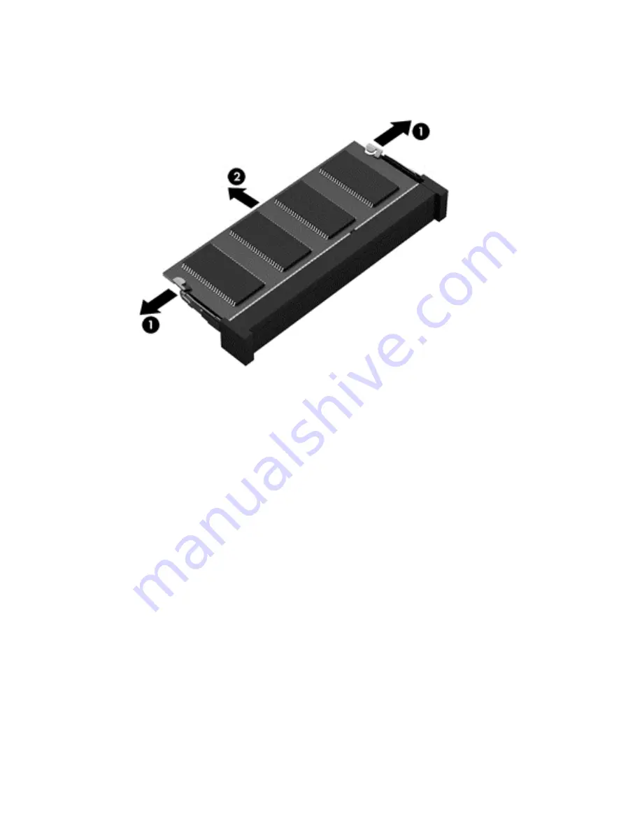
Spread the retaining tabs 

(1)

 on each side of the memory module slot to release the memory

module. (The memory module tilts up.)

4.

Remove the memory module 

(2)

 by pulling the module away from the slot at an angle.

Reverse this procedure to install a memory module.

Component replacement procedures

43

Содержание mt41

Страница 1: ...HP mt41 Mobile Thin Client Maintenance and Service Guide ...

Страница 2: ...tituting an additional warranty HP shall not be liable for technical or editorial errors or omissions contained herein Product notice This guide describes features that are common to most models Some features may not be available on your computer Software terms By installing copying downloading or otherwise using any software product preinstalled on this computer you agree to be bound by the terms...

Страница 3: ...hat should only be accessed by an authorized service provider See Chapter 5 Removal and replacement procedures for Customer Self Repair parts for details Accessing parts described in Chapter 6 Removal and replacement procedures for Authorized Service Provider only parts can damage the computer or void your warranty iii ...

Страница 4: ...iv Important Notice about Customer Self Repair Parts ...

Страница 5: ...allow another hard surface such as an adjoining optional printer or a soft surface such as pillows or rugs or clothing to block airflow Also do not allow the AC adapter to contact the skin or a soft surface such as pillows or rugs or clothing during operation The computer and the AC adapter comply with the user accessible surface temperature limits defined by the International Standard for Safety ...

Страница 6: ...vi Safety warning notice ...

Страница 7: ...storage devices 21 Miscellaneous parts 21 Sequential part number listing 23 4 Removal and replacement procedures preliminary requirements 26 Tools required 26 Service considerations 26 Plastic parts 26 Cables and connectors 27 Drive handling 27 Grounding guidelines 27 Electrostatic discharge damage 27 Packaging and transporting guidelines 29 Workstation guidelines 29 5 Removal and replacement proc...

Страница 8: ...utton board 75 Smart card reader 77 TouchPad button board 79 7 Computer Setup BIOS MultiBoot and HP PC Hardware Diagnostics UEFI 81 Using Computer Setup 81 Starting Computer Setup 81 Navigating and selecting in Computer Setup 81 Restoring factory settings in Computer Setup 82 Updating the BIOS 83 Determining the BIOS version 83 Downloading a BIOS update 83 Using MultiBoot 84 About the boot device ...

Страница 9: ...UEFI to a USB device 86 8 Specifications 88 Computer specifications 88 9 Statement of Volatility 89 Non volatile memory usage 90 Questions and answers 92 10 Power cord set requirements 93 Requirements for all countries 93 Requirements for specific countries and regions 94 11 Recycling 96 Index 97 ix ...

Страница 10: ...x ...

Страница 11: ...2 nits with WWAN with camera 14 0 in 35 56 cm HD AG SVA 45 color gamut 1366 768 resolution 200 cd m2 nits with WWAN without camera All panels have LED backlight Memory Two customer accessible upgradable memory module slots Support for DDR3L 1600 MHz PC3L 12800 dual channel memory Support for up to 8192 MB of system RAM in the following configurations 8192 MB total system memory 4096 MB 2 4096 MB t...

Страница 12: ...ternal media cards HP 2 in 1 multiformat Digital Media Reader Slot Reads data from and writes data to digital memory cards such as Secure Digital SD Ports AC adapter HP Smart Audio in mono microphone audio out stereo headphone combo jack DisplayPort 1 2 Docking RJ 45 Ethernet USB 2 0 3 USB 2 0 charging 1 VGA Dsub 15 pin supporting 1920 1200 external resolution 75 Hz hot plug and unplug and autodet...

Страница 13: ...y lock Trusted platform module TPM 1 2 Infineon soldered down Preboot Authentication Password smart card Integrated smart card reader Operating system Preinstalled Windows Embedded Standard 7 32 bit Serviceability End user replaceable parts AC adapter Battery system Fan Keyboard Memory modules expansion and primary Optical drive SSD WLAN module WWAN module 3 ...

Страница 14: ...s the TouchPad on and off 2 TouchPad zone Moves the pointer and selects or activates items on the screen 3 Left TouchPad button Functions like the left button on an external mouse 4 Right TouchPad button Functions like the right button on an external mouse 4 Chapter 2 External component identification ...

Страница 15: ...ight Amber The TouchPad is off Off The TouchPad is on 4 Microphone mute light Amber The microphone is muted Off The microphone is on 5 Num lock light On Num lock is on 6 Wireless light White An integrated wireless device such as a wireless local area network WLAN device is on Amber All wireless devices are off 7 Mute light Amber Computer sound is off Off Computer sound is on Top 5 ...

Страница 16: ...lt in the loss of unsaved information If the computer has stopped responding and Windows shutdown procedures are ineffective press and hold the power button for at least 5 seconds to turn off the computer To learn more about your power settings Select Start Control Panel System and Security Power Options 2 Speakers 2 Produce sound 3 Wireless button Turns the wireless feature on or off but does not...

Страница 17: ...ction keys Execute frequently used system functions when pressed in combination with the fn key 5 Windows applications key Displays a shortcut menu for items beneath the cursor 6 Embedded numeric keypad When the keypad is turned on it can be used like an external numeric keypad Each key on the keypad performs the function indicated by the icon in the upper right corner of the key 7 num lk key Turn...

Страница 18: ...connected to external power and the battery is charged from 90 to 99 percent Amber The computer is connected to external power and the battery is charged from 0 to 90 percent Blinking amber A battery that is the only available power source has reached a low battery level When the battery reaches a critical battery level the battery light begins blinking rapidly Off The battery is fully charged 4 D...

Страница 19: ...nnector that supports both audio out headphone and audio in microphone 2 USB ports 2 Connect optional USB devices and provide enhanced USB power performance NOTE These ports support USB 2 0 by default For details about activating the USB 3 0 port functionality see the User Guide 3 Dual mode DisplayPort Connects an optional digital display device such as a high performance monitor or projector 4 Ex...

Страница 20: ... from and writes data to memory cards such as Secure Digital SD 5 USB port Connects optional USB devices and provide enhanced USB power performance NOTE These ports support USB 2 0 by default For details about activating the USB 3 0 port functionality see the User Guide 6 Upgrade bay optical drive shown The upgrade bay can hold an optical drive that reads and writes select models only to an optica...

Страница 21: ...ecords video and captures still photographs 6 Internal display switch Turns off the display if the display is closed while the power is on NOTE The display switch is not visible on the outside of the computer The antennas are not visible on the outside of the computer For optimal transmission keep the areas immediately around the antennas free from obstructions To see wireless regulatory notices s...

Страница 22: ...nmental agency that regulates wireless devices in your country or region If you replace the module and then receive a warning message remove the module to restore computer functionality and then contact support 2 Battery release latch open position Releases the battery 3 Battery release latch locked position Holds the battery 4 Docking connector Connects an optional docking device 5 Service door r...

Страница 23: ...rder parts for the computer IMPORTANT All labels described in this section will be located in one of 3 places depending on your computer model Affixed to the bottom of the computer located in the battery bay or under the service door Service label Provides important information to identify your computer When contacting support you will probably be asked for the serial number and possibly for the p...

Страница 24: ...ry label s Provide s regulatory information about the computer Wireless certification label s Provide s information about optional wireless devices and the approval markings of some of the countries or regions in which the devices have been approved for use 14 Chapter 2 External component identification ...

Страница 25: ...ter major components NOTE Details about your computer including model serial number product key and length of warranty are on the service tag at the bottom of your computer See Labels on page 13 for details Computer major components 15 ...

Страница 26: ...he display assembly is spared at the subcomponent level only For more display assembly spare part information see Display assembly subcomponents on page 20 14 0 in 35 56 cm HD display assembly equipped with a webcam 16 Chapter 3 Illustrated parts catalog ...

Страница 27: ...38687 D61 For use in Israel 738687 BB1 For use in Italy 738687 061 For use in Japan 738687 291 For use in Latin America 738687 161 For use in the Netherlands 738687 B31 For use in Northwest Africa 738687 FP1 For use in Norway 738687 091 For use in Portugal 738687 131 For use in Romania 738687 271 For use in Russia 738687 251 For use in Saudi Arabia 738687 171 For use in Slovenia 738687 BA1 For use...

Страница 28: ...hics dual core 3 0 GHz 2 5 GHz 35 W 1 MB L2 cache 685990 001 12 USB board 738400 001 13 System board includes replacement thermal material For use only on computer models equipped with a WWAN 746017 001 For use only on computer models not equipped with a WWAN 746018 001 14 Power button board included cable 738399 001 15 Memory modules PC3L 12800 1600 MHz 4 GB 691740 001 16 Fan 738685 001 17 Optica...

Страница 29: ...0 001 HP lt4112 LTE HSPA Mobile Broadband Module 704031 001 23 RTC battery includes cable and double sided adhesive 651948 001 24 Solid state drive SSD 16 GB SATA includes hard drive bracket cable and screws 750751 001 25 Service door 738682 001 Service door RCTO 748357 001 Computer major components 19 ...

Страница 30: ...dule 738397 001 3 Display panel 14 in 35 56 cm WLED HD AG SVA flat display panel 747751 001 4 Left and right display hinges included in Display Hinge Kit 738396 001 5 Display panel cable includes webcam microphone module cable and tape 738684 001 6 Display back cover includes WLAN and WWAN antenna cables and gaskets 738680 001 20 Chapter 3 Illustrated parts catalog ...

Страница 31: ... shown included with Plastics Kit spare part number 738402 001 Miscellaneous parts Component Spare part number AC adapter 65 W HP Smart adapter PFC 3 wire 4 5 mm select models only 693710 001 65 W HP Smart adapter NPFC 3 wire 4 5 mm 693711 001 Power cord 3 pin black 1 83 m For use in Argentina 490371 D01 For use in Australia 490371 011 For use in Denmark 490371 081 For use in Europe 490371 021 Mas...

Страница 32: ...ina 490371 AA1 For use in South Africa 490371 AR1 For use in South Korea 490371 AD1 For use in Switzerland 490371 111 For use in Taiwan 490371 AB1 For use in Thailand 490371 201 For use in the United Kingdom and Singapore 490371 031 Expansion base 688169 001 Plastics Kit includes WLAN bracket and optical drive weight saver 738402 001 Rubber Kit 738403 001 Screw Kit 738689 001 22 Chapter 3 Illustra...

Страница 33: ...lack 1 83 m 490371 AD1 A Power cord for use in South Korea 3 pin black 1 83 m 490371 AR1 A Power cord for use in South Africa 3 pin black 1 83 m 490371 BB1 A Power cord for use in Israel 3 pin black 1 83 m 490371 D01 A Power cord for use in Argentina 3 pin black 1 83 m 490371 D61 A Power cord for use in India 3 pin black 1 83 m 651948 001 N RTC battery includes cable and double sided adhesive 6859...

Страница 34: ...sure 738682 001 A Service door 738683 001 C Power connector cable 738684 001 C Display panel cable includes webcam microphone module cable and tape 738685 001 A Fan 738686 001 C Heat sink assembly includes replacement thermal material 738687 001 A Keyboard for use in the United States includes keyboard cable 738687 031 A Keyboard for use in the United Kingdom and Singapore includes keyboard cable ...

Страница 35: ...ludes keyboard cable 738687 BA1 A Keyboard for use in Slovenia includes keyboard cable 738687 BB1 A Keyboard for use in Israel includes keyboard cable 738687 BG1 A Keyboard for use in Switzerland includes keyboard cable 738687 D61 A Keyboard for use in India includes keyboard cable 738687 DB1 A Keyboard for use in Canada includes keyboard cable 738687 DD1 A Keyboard for use in Iceland includes key...

Страница 36: ...rations that you must keep in mind during disassembly and assembly procedures NOTE As you remove each subassembly from the computer place the subassembly and all accompanying screws away from the work area to prevent damage Plastic parts CAUTION Using excessive force during disassembly and reassembly can damage plastic parts Use care when handling the plastic parts Apply pressure only at the point...

Страница 37: ...kette or disc is not in the drive and be sure that the optical drive tray is closed Handle drives on surfaces covered with at least one inch of shock proof foam Avoid dropping drives from any height onto any surface After removing a hard drive an optical drive or a diskette drive place it in a static proof bag Avoid exposing an internal hard drive to products that have magnetic fields such as moni...

Страница 38: ...le shows how humidity affects the electrostatic voltage levels generated by different activities CAUTION A product can be degraded by as little as 700 V Typical electrostatic voltage levels Relative humidity Event 10 40 55 Walking across carpet 35 000 V 15 000 V 7 500 V Walking across vinyl floor 12 000 V 5 000 V 3 000 V Motions of bench worker 6 000 V 800 V 400 V Removing DIPS from plastic tube 2...

Страница 39: ... to ground and that proper materials are selected to avoid static charging When grounding is not possible use an ionizer to dissipate electric charges Workstation guidelines Follow these grounding workstation guidelines Cover the workstation with approved static shielding material Use a wrist strap connected to a properly grounded work surface and use properly grounded tools and equipment Use cond...

Страница 40: ...operator and ground To be effective the conductive must be worn in contact with the skin The following grounding equipment is recommended to prevent electrostatic damage Antistatic tape Antistatic smocks aprons and sleeve protectors Conductive bins and other assembly or soldering aids Nonconductive foam Conductive tabletop workstations with ground cords of one megohm resistance Static dissipative ...

Страница 41: ...ures described here to access and replace Customer Self Repair parts successfully NOTE Details about your computer including model serial number product key and length of warranty are on the service tag at the bottom of your computer See Labels on page 13 for details This chapter provides removal and replacement procedures for Customer Self Repair parts There are as many as 15 screws that must be ...

Страница 42: ...ded by HP or a compatible battery purchased from HP CAUTION Removing a user replaceable battery that is the sole power source for the computer can cause loss of information To prevent loss of information save your work or shut down the computer through Windows before removing the battery To remove the battery CAUTION Removing a battery that is the sole power source for the computer can cause loss ...

Страница 43: ...y unplugging the power cord from the computer 3 Disconnect all external devices from the computer 4 Remove the battery see Battery on page 32 Remove the service door 1 Turn the computer upside down on a flat surface with the battery bay toward you 2 Slide the service door release latch to the left 1 and then remove the optional Phillips screw if the screw is being used 2 NOTE If you want to use th...

Страница 44: ...oving the hard drive follow these steps 1 Turn off the computer If you are unsure whether the computer is off or in Hibernation turn the computer on and then shut it down through the operating system 2 Disconnect the power from the computer by unplugging the power cord from the computer 3 Disconnect all external devices from the computer 4 Remove the battery see Battery on page 32 5 Remove the ser...

Страница 45: ... connecting the hard drive to the computer 4 Using the plastic tab 3 pull and lift the hard drive and then pull the hard drive 4 out of the hard drive bay 5 If it is necessary to disassemble the hard drive perform the following steps a Disconnect the hard drive cable 1 from the drive b Remove the four Phillips screws 2 from the hard drive Component replacement procedures 35 ...

Страница 46: ...computer on and then shut it down through the operating system 2 Disconnect the power from the computer by unplugging the power cord from the computer 3 Disconnect all external devices from the computer 4 Remove the battery see Battery on page 32 5 Remove the service door see Service door on page 33 Remove the optical drive 1 Position the computer upside down with the left side toward you 2 Loosen...

Страница 47: ...4 Remove the optical drive or weight saver 3 Reverse this procedure to install the optical drive Component replacement procedures 37 ...

Страница 48: ...turn the computer on and then shut it down through the operating system 2 Disconnect the power from the computer by unplugging the power cord from the computer 3 Disconnect all external devices from the computer 4 Remove the battery see Battery on page 32 5 Remove the service door see Service door on page 33 Remove the WWAN module 1 Turn the computer upside down on a flat surface with the battery ...

Страница 49: ...f the WWAN antenna cables are not connected to the terminals on the WWAN module protective sleeves should be installed on the antenna connectors as shown in the following illustration Reverse this procedure to install the WWAN module Component replacement procedures 39 ...

Страница 50: ...onnect the power from the computer by unplugging the power cord from the computer 3 Disconnect all external devices from the computer 4 Remove the battery see Battery on page 32 5 Remove the service door see Service door on page 33 6 If there is a WWAN module remove the WWAN module see WWAN module on page 38 Remove the WLAN module 1 Turn the computer upside down on a flat surface with the battery ...

Страница 51: ...lot at an angle NOTE If the WLAN antenna cables are not connected to the terminals on the WLAN module protective sleeves should be installed on the antenna connectors as shown in the following illustration Reverse this procedure to install the WLAN module Component replacement procedures 41 ...

Страница 52: ...IOS see Updating the BIOS on page 83 Before removing a memory module follow these steps 1 Turn off the computer If you are unsure whether the computer is off or in Hibernation turn the computer on and then shut it down through the operating system 2 Disconnect the power from the computer by unplugging the power cord from the computer 3 Disconnect all external devices from the computer 4 Remove the...

Страница 53: ... the memory module slot to release the memory module The memory module tilts up 4 Remove the memory module 2 by pulling the module away from the slot at an angle Reverse this procedure to install a memory module Component replacement procedures 43 ...

Страница 54: ...he computer 3 Disconnect all external devices from the computer 4 Remove the battery see Battery on page 32 5 Remove the service door see Service door on page 33 Remove the fan 1 Turn the computer upside down on a flat surface with the battery bay toward you 2 Disconnect the fan cable 1 from the system board 3 Loosen the two captive Phillips screws 2 that secure the fan to the top cover 4 Remove t...

Страница 55: ...nd Finland 738687 B71 For use in Iceland 738687 DD1 For use in Switzerland 738687 BG1 For use in India 738687 D61 For use in Taiwan 738687 AB1 For use in Israel 738687 BB1 For use in Thailand 738687 281 For use in Italy 738687 061 For use in Turkey 738687 141 For use in Japan 738687 291 For use in the United Kingdom and Singapore 738687 031 For use in Latin America 738687 161 For use in the United...

Страница 56: ...he tabs and then press on the back of the keyboard until the keyboard disengages from the computer 5 Push down on the keyboard and then slide the keyboard 2 toward the front of the computer 6 Lift the keyboard 3 up 7 Swing the keyboard 1 up and forward until it rests upside down on the palm rest 46 Chapter 5 Removal and replacement procedures for Customer Self Repair parts ...

Страница 57: ...e the ZIF connector 2 by lifting connector tab 9 Disconnect the keyboard cable 3 from the system board 10 Remove the keyboard 4 Reverse this procedure to install the keyboard Component replacement procedures 47 ...

Страница 58: ...ing model serial number product key and length of warranty are on the service tag at the bottom of your computer See Labels on page 13 for details This chapter provides removal and replacement procedures for Authorized Service Provider only parts There are as many as 68 screws that must be removed replaced and or loosened when servicing the computer Make special note of each screw size and locatio...

Страница 59: ...nal devices from the computer 4 Remove the battery see Battery on page 32 Remove the panel 1 Open the computer with the display facing you 2 Flex the inside edges of the top edge 1 the left and right sides 2 and the bottom edge 3 of the display bezel until the bezel disengages from the display enclosure 3 Remove the display bezel 4 1 Remove the four Phillips screws 1 that secure the display panel ...

Страница 60: ...pside down in front of the display back cover 4 Release the adhesive strip 2 that secures the display panel cable connector to the display panel 5 Remove the display panel 3 Reverse this procedure to replace the panel 50 Chapter 6 Removal and replacement procedures for Authorized Service Provider parts ...

Страница 61: ...puter 4 Remove the battery see Battery on page 32 and then remove the following components a Service door see Service door on page 33 b Fan see Fan on page 44 Remove the heat sink assembly 1 Position the computer upside down with the battery bay facing you 2 Following the 1 through 4 sequence stamped into the processor heat sink loosen the four Phillips captive screws 1 that secure the processor h...

Страница 62: ...embly is removed Replacement thermal material is included with the heat sink assembly processor and system board spare part kits Thermal paste is used on the processor 1 and the heat sink section 2 that services it Reverse this procedure to install the heat sink assembly 52 Chapter 6 Removal and replacement procedures for Authorized Service Provider parts ...

Страница 63: ... computer on and then shut it down through the operating system 2 Disconnect the power from the computer by unplugging the power cord from the computer 3 Disconnect all external devices from the computer 4 Remove the battery see Battery on page 32 and then remove the following components a Service door see Service door on page 33 b Fan see Fan on page 44 c Heat sink assembly see Heat sink assembly...

Страница 64: ...riangle 3 on the processor must be aligned with the triangle icon 4 embossed on the processor socket when you install the processor Reverse this procedure to install the processor 54 Chapter 6 Removal and replacement procedures for Authorized Service Provider parts ...

Страница 65: ... computer by unplugging the power cord from the computer 3 Disconnect all external devices from the computer 4 Remove the battery see Battery on page 32 5 Remove the service door see Service door on page 33 Remove the base enclosure 1 Position the computer upside down with the battery bay facing you 2 Remove the two front rubber screw covers 1 and 2 the one screw cover 3 on the middle left edge th...

Страница 66: ...e the base enclosure to the top cover 4 Remove the three Torx screws in the battery bay 6 and the two back cover screws 7 NOTE Make sure the wireless cables route cleanly through the opening in the base enclosure to prevent them from catching on the enclosure NOTE Make sure any SD cards or SD blanks have been removed 5 Detach the clips 1 in front of the hard drive area before lifting the base encl...

Страница 67: ...6 Remove the base enclosure 2 from the top cover Reverse this procedure to install the base enclosure Component replacement procedures 57 ...

Страница 68: ...bernation turn the computer on and then shut it down through the operating system 2 Disconnect the power from the computer by unplugging the power cord from the computer 3 Disconnect all external devices from the computer 4 Remove the battery see Battery on page 32 and then remove the following components a Service door see Service door on page 33 b Base enclosure see Base enclosure on page 55 Rem...

Страница 69: ... and move the wireless cables out of the way 5 Disconnect the display panel cable 1 from the system board and remove the display panel cable 2 from the routing on the right speaker 6 Turn the computer right side up with the battery bay toward you Component replacement procedures 59 ...

Страница 70: ...he display assembly 10 If it is necessary to replace the display bezel or any of the LED display assembly subcomponents a Flex the inside edges of the top edge 1 the left and right sides 2 and the bottom edge 3 of the display bezel until the bezel disengages from the display enclosure b Remove the display bezel 4 60 Chapter 6 Removal and replacement procedures for Authorized Service Provider parts...

Страница 71: ... of tools screws and any other foreign objects Failure to follow this caution can result in damage to the display panel b Lift the top edge of the display panel 2 c Swing the display panel 1 up and forward until it rests upside down in front of the display back cover d Release the adhesive strip 2 that secures the display panel cable connector to the display panel e Remove the display panel 3 Comp...

Страница 72: ...a Lift the module 1 from the display back cover The module is attached to the display back cover with double sided adhesive b Detach the cable 2 from the module c Remove the module 13 If it is necessary to replace the display hinges a Remove the six Phillips screws 1 that secure the display hinges to the display panel b Remove the two Torx screws 2 on the left hinge 62 Chapter 6 Removal and replac...

Страница 73: ... the right hinge snaps 1 and remove the hinges 2 14 If it is necessary to replace the display panel cable Reverse this procedure to reassemble and install the display assembly Component replacement procedures 63 ...

Страница 74: ...ices from the computer 4 Remove the battery see Battery on page 32 and then remove the following components a Service door see Service door on page 33 b Base enclosure see Base enclosure on page 55 Remove the USB board 1 Position the top cover upside down with the battery bay facing away from you 2 Remove the three Torx screws 1 connecting the USB board to the system board 3 Lift the inside edge o...

Страница 75: ...r by unplugging the power cord from the computer 3 Disconnect all external devices from the computer 4 Remove the battery see Battery on page 32 and then remove the following components a Service door see Service door on page 33 b Base enclosure see Base enclosure on page 55 Remove the speakers 1 Position the top cover upside down with the battery bay facing you 2 Disconnect the speaker cables 1 a...

Страница 76: ...f or in Hibernation turn the computer on and then shut it down through the operating system 2 Disconnect the power from the computer by unplugging the power cord from the computer 3 Disconnect all external devices from the computer 4 Remove the battery see Battery on page 32 and then remove the following components a Service door see Service door on page 33 b Base enclosure see Base enclosure on p...

Страница 77: ...over upside down with the battery bay facing you 2 Remove the Torx screw 1 from the base enclosure 3 Remove the power connector cable 2 from the base enclosure Reverse this procedure to install the power connector cable Component replacement procedures 67 ...

Страница 78: ...ery on page 32 and then remove the following components a Service door see Service door on page 33 b Base enclosure see Base enclosure on page 55 c USB board see USB board on page 64 d Speakers see Speakers on page 65 e Power connector cable see Power connector cable on page 66 Remove the power button board 1 Turn the top cover upside down with the front toward you 2 Lift up the power button board...

Страница 79: ... Remove the battery see Battery on page 32 and then remove the following components a Service door see Service door on page 33 b Hard drive see Hard drive on page 34 c Optical drive see Optical drive on page 36 d Keyboard see Keyboard on page 45 e Base enclosure see Base enclosure on page 55 f USB board see USB board on page 64 NOTE When replacing the system board be sure that the following compon...

Страница 80: ...ing from the system board 1 Power button board ZIF connector 2 Function button board reverse ZIF connector 3 Turn the top cover upside down 70 Chapter 6 Removal and replacement procedures for Authorized Service Provider parts ...

Страница 81: ...isconnect the following cables from the system board 1 Card reader ZIF connector 2 Power connector cable 3 Right speaker cable 4 Display panel cable 5 Left speaker cable Component replacement procedures 71 ...

Страница 82: ...p cover 6 Lift the middle left side 1 of the system board and then remove the board 2 by sliding it up and to the left at an angle Reverse this procedure to install the system board 72 Chapter 6 Removal and replacement procedures for Authorized Service Provider parts ...

Страница 83: ...r 3 Disconnect all external devices from the computer 4 Remove the battery see Battery on page 32 and then remove the following components a Service door see Service door on page 33 b Hard drive see Hard drive on page 34 c Optical drive see Optical drive on page 36 d Keyboard see Keyboard on page 45 e Base enclosure see Base enclosure on page 55 f USB board see USB board on page 64 g System board ...

Страница 84: ...re The RTC battery is attached to the base enclosure with double sided adhesive 4 Remove the RTC battery and cable Reverse this procedure to install the RTC battery 74 Chapter 6 Removal and replacement procedures for Authorized Service Provider parts ...

Страница 85: ...ove the battery see Battery on page 32 and then remove the following components a Service door see Service door on page 33 b Hard drive see Hard drive on page 34 c Optical drive see Optical drive on page 36 d Keyboard see Keyboard on page 45 e Base enclosure see Base enclosure on page 55 f USB board see USB board on page 64 g System board see System board on page 69 Remove the function button boar...

Страница 86: ...4 Remove the function button board 3 Reverse this procedure to install the function button board 76 Chapter 6 Removal and replacement procedures for Authorized Service Provider parts ...

Страница 87: ...onnect all external devices from the computer 4 Remove the battery see Battery on page 32 and then remove the following components a Service door see Service door on page 33 b Hard drive see Hard drive on page 34 c Optical drive see Optical drive on page 36 d Keyboard see Keyboard on page 45 e Base enclosure see Base enclosure on page 55 f USB board see USB board on page 64 g System board see Syst...

Страница 88: ...IF connector 1 to which the smart card reader cable is attached 5 Lift the clip 2 that secures the smart card reader to the base enclosure 6 Release the clip 3 7 Remove the smart card reader 4 Reverse this procedure to install the smart card reader 78 Chapter 6 Removal and replacement procedures for Authorized Service Provider parts ...

Страница 89: ...emove the following components a Service door see Service door on page 33 b Hard drive see Hard drive on page 34 c Optical drive see Optical drive on page 36 d Keyboard see Keyboard on page 45 e Base enclosure see Base enclosure on page 55 f USB board see USB board on page 64 g System board see System board on page 69 h Smart card reader see Smart card reader on page 77 Remove the TouchPad button ...

Страница 90: ...4 Remove the TouchPad button board 3 Reverse this procedure to install the TouchPad button board 80 Chapter 6 Removal and replacement procedures for Authorized Service Provider parts ...

Страница 91: ...e the Press the ESC key for Startup Menu message is displayed at the bottom of the screen 2 Press f10 to enter Computer Setup Navigating and selecting in Computer Setup To navigate and select in Computer Setup follow these steps 1 Turn on or restart the computer and then press esc while the Press the ESC key for Startup Menu message is displayed at the bottom of the screen NOTE You can use either ...

Страница 92: ...faults will not change the hard drive mode To return all settings in Computer Setup to the values that were set at the factory follow these steps 1 Turn on or restart the computer and then press esc while the Press the ESC key for Startup Menu message is displayed at the bottom of the screen 2 Press f10 to enter Computer Setup 3 Use a pointing device or the arrow keys to select Main Restore Defaul...

Страница 93: ...S update only when the computer is connected to reliable external power using the AC adapter Do not download or install a BIOS update while the computer is running on battery power docked in an optional docking device or connected to an optional power source During the download and installation follow these instructions Do not disconnect power on the computer by unplugging the power cord from the ...

Страница 94: ... card NIC hard drives and USB devices Boot devices contain bootable media or files that the computer needs to start and operate properly NOTE Some boot devices must be enabled in Computer Setup before they can be included in the boot order You can change the order in which the computer searches for a boot device by changing the boot order in Computer Setup You can also press esc while the Press th...

Страница 95: ...ot device for the current startup sequence follow these steps 1 Open the Select Boot Device menu by turning on or restarting the computer and then pressing esc while the Press the ESC key for Startup Menu message is displayed at the bottom of the screen 2 Press f9 3 Use a pointing device or the arrow keys to select a boot device then press enter Setting a MultiBoot Express prompt To start Computer...

Страница 96: ...ly The tool runs outside of the operating system to isolate hardware failures from issues that may be caused by the operating system or other software components To start HP PC Hardware Diagnostics UEFI 1 Turn on or restart the computer quickly press esc and then press f2 After pressing f2 the BIOS searches three places for the HP PC Hardware Diagnostics UEFI tools in the following order a Connect...

Страница 97: ...r computer model and then select your operating system 5 In the Diagnostic section click HP UEFI Support Environment or Click Download and then select Run Using HP PC Hardware Diagnostics UEFI select models only 87 ...

Страница 98: ...b Weight computer equipped 9 cell battery and ODD 2 31 kg 5 09 lb Input power Operating voltage and current 19 5 V dc 3 33 A 65 W Temperature Operating 5 C to 35 C 41 F to 95 F Nonoperating 20 C to 60 C 4 F to 140 F Relative humidity non condensing Operating 10 to 90 Nonoperating 5 to 95 Maximum altitude unpressurized Operating 15 m to 3 048 m 50 ft to 10 000 ft Nonoperating 15 m to 12 192 m 50 ft...

Страница 99: ...gh j below to restore the nonvolatile memory that can contain personal data Restoring or re programming nonvolatile memory that does not store personal data is neither necessary nor recommended a Enter BIOS F10 Setup by powering on the system and pressing F10 when prompted near the bottom of the display or press the ESC key to display the start up menu then press F10 If the system has a BIOS admin...

Страница 100: ...onfiguration memory CMOS 256 Bytes No Yes Stores system date and time and limited keyboard controller data Using the F10 Setup utility or changing the M Windows date time This memory is not write protected HP recommends password protecting the F10 Setup utility Controller NIC EEPROM 64 Kbytes not customer accessible No Yes Store NIC configuration and NIC firmware Using a utility from the NIC vendo...

Страница 101: ...Programmed at the factory Tools for writing data to this memory are not publicly available but can be obtained from the silicon vendor A utility is required for writing data to this memory and is made available through newer versions of the driver if the flash requires an upgrade 802 11 WLAN EEPROM 4kb to 8kb No Yes Stores configuration and calibration data Programmed at the factory Tools for writ...

Страница 102: ...n the memory module is not installed in a PC There are various third party tools available to read SPD memory 3 Does the Firmware Hub for System BIOS contain the BIOS program Is this chip writable and if so how The Firmware Hub does contain the BIOS program and is writable A utility is required to perform the write function 4 In some PC systems the Firmware Hub for System BIOS is a flash memory ch...

Страница 103: ...equirements are applicable to all countries and regions The length of the power cord set must be at least 1 0 m 3 3 ft and no more than 2 0 m 6 5 ft All power cord sets must be approved by an acceptable accredited agency responsible for evaluation in the country or region where the power cord set will be used The power cord sets must have a minimum current capacity of 10 A and a nominal voltage ra...

Страница 104: ... Denmark DEMKO 1 Finland FIMKO 1 France UTE 1 Germany VDE 1 India ISI 1 Israel SII 1 Italy IMQ 1 Japan JIS 3 The Netherlands KEMA 1 New Zealand SANZ 1 Norway NEMKO 1 The People s Republic of China CCC 4 Saudi Arabia SASO 7 Singapore PSB 1 South Africa SABS 1 South Korea KTL 5 Sweden SEMKO 1 Switzerland SEV 1 Taiwan BSMI 6 Thailand TISI 1 The United Kingdom ASTA 1 94 Chapter 10 Power cord set requi...

Страница 105: ...or size The wall plug must be a two pole grounding type with a Japanese Industrial Standard C8303 7 A 125 V ac configuration 4 The flexible cord must be Type RVV 3 conductor 0 75 mm conductor size Power cord set fittings appliance coupler and wall plug must bear the CCC certification mark 5 The flexible cord must be Type H05VV F 3 conductor 0 75 mm conductor size KTL logo and individual approval n...

Страница 106: ...in general household waste Follow the local laws and regulations in your area for battery disposal HP encourages customers to recycle used electronic hardware HP original print cartridges and rechargeable batteries For more information about recycling programs see the HP Web site at http www hp com recycle 96 Chapter 11 Recycling ...

Страница 107: ...back cover spare part numbers 20 24 58 display bezel removal 60 spare part numbers 20 25 display bezel cover spare part numbers 58 display hinge spare part number 24 58 Display Hinge Kit spare part number 24 58 display panel product description 1 removal 49 61 spare part number 20 25 49 58 display panel cable spare part number 20 24 58 docking connector identifying 12 docking device spare part num...

Страница 108: ...al 62 spare part number 20 58 spare part numbers 24 microphone mute light identifying 5 model name 1 mute light identifying 5 N network jack identifying 10 num lock light 5 O operating system product description 3 optical drive identifying 10 precautions 27 removal 36 spare part numbers 18 21 25 36 optical drive eject button identifying 10 optical drive light identifying 10 optical drive weight sa...

Страница 109: ...e part number 18 24 65 speaker mute light identifying 5 speakers identifying 6 specifications computer 88 SSD removal 34 spare part number 25 spare part numbers 19 21 34 system board removal 69 spare part numbers 18 25 69 T tools required 26 top cover removal 60 spare part number 18 24 TouchPad buttons 4 spare part number 24 TouchPad button board removal 79 spare part number 18 79 TouchPad light i...

Отзывы: